Figure 7 – uploaded by Wolfgang Busse

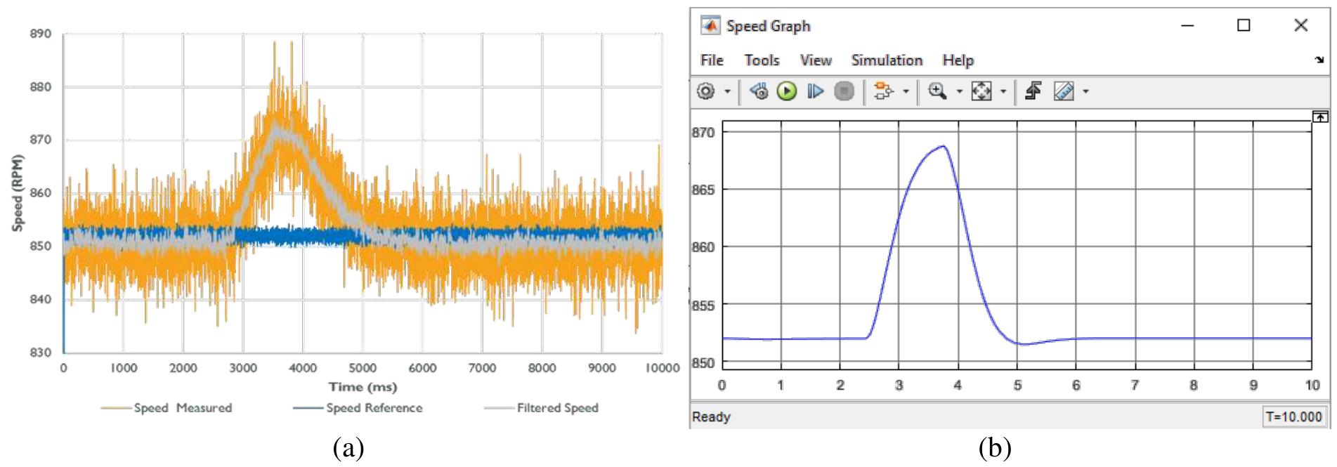
Figure 7 7. Schematic Diagram of the System To set the parameters of the corresponding PI controller on the engine. Making this model will be tailored to the results of the test engine running. In the original design of the system, the torque or speed through two reference potentiometers are set. In the deviation of the specified value of the applied speed or torque value, this means adjusting the combustion and power rate to achieve the required process parameters (figure 9). By setting a torque and a speed reference potentiometer generates the corresponding set point for speed (N) and torque (Tioaa). From calculation on the system, the controller receives information about the size of the currently applied actual value from speed (N’) and torque (T). Actual value (N’) and setpoint (N) of speed
Related Figures (24)


Connect with 287M+ leading minds in your field
Discover breakthrough research and expand your academic network
Join for free