580 California St., Suite 400
San Francisco, CA, 94104

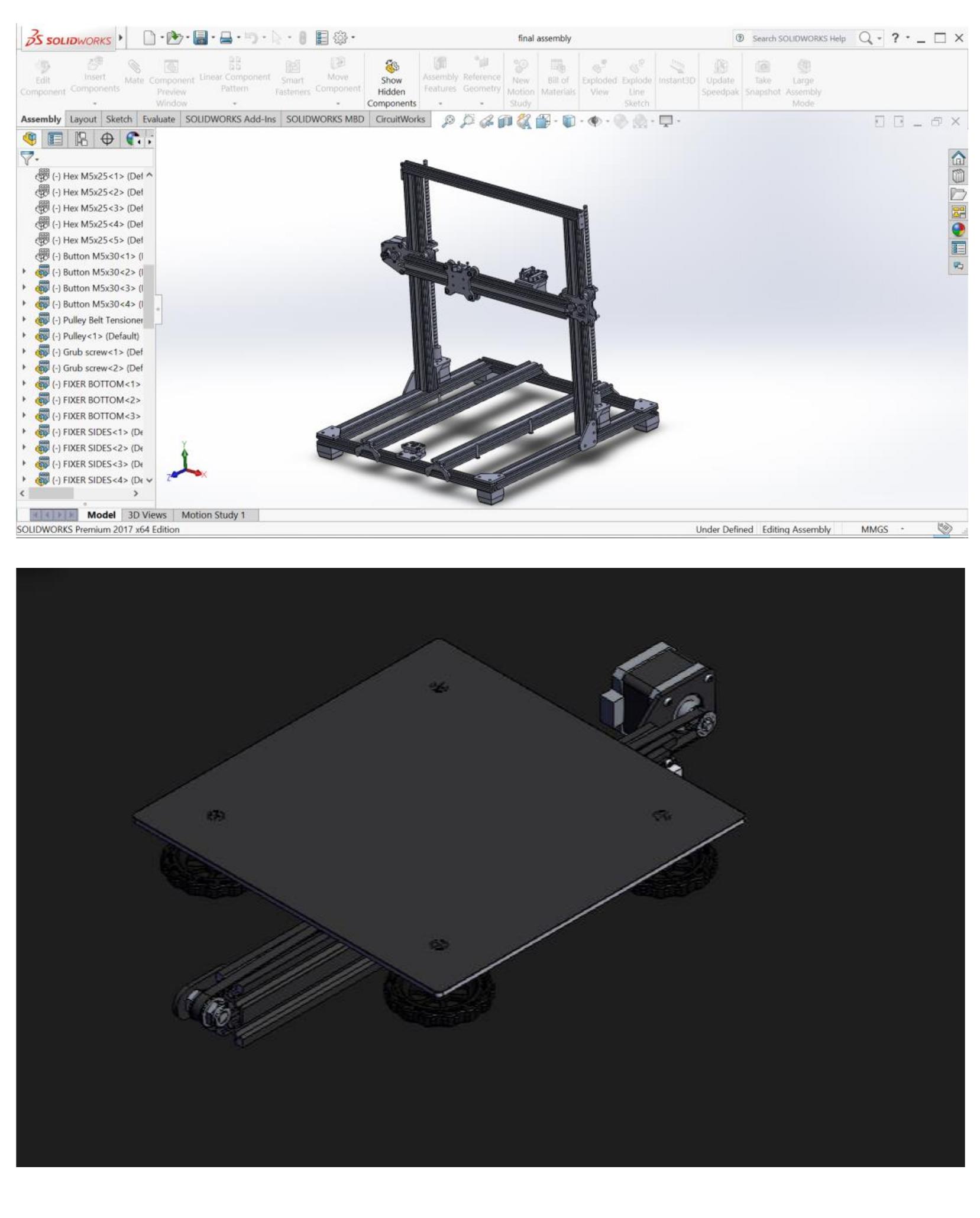
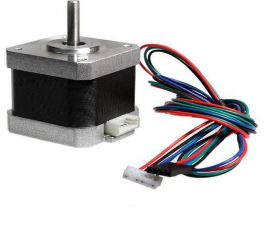
Figure 57 ‘he rotation of the motor is transmitted by rotating the lead screw connected to the bed by a flang ut and a shaft coupling as shown. A couple The generated motor is transmitted to the lead screv y shaft coupling and flange beads. When the motor rotates, for example clockwise, the shaf oupling rotate the lead screw in the same direction, for example clockwise. Bed is connected tc 1e lead screw by a threaded coupling, this makes the bed move vertical direction when the lea crew rotates.These cylindrical bars are securely fixed to the frame. The timing belt is mountec n a motor-driven pulley on one side and on a support pulley on the other side. The carriage i: ttached to the lower timing belt of the buckle,such that the movement of the belt leads to th 1ovement of the carriage. When The engine rotates in one direction, the wagons are connected t 1e lower belt at the loop moves back and forth depending on the motor orientation. The tw« rotors must be perfectly synchronized for high quality impression.To design this Y-axi novement, the slides must first designed. The sliding table is designed to fit the motor, pulley anc old X —shaft rod. These strollers are symmetrical so there are no imbalance issues and therefore 1e size of the trolley is determined by the required installation area by the motor, support pulle} nd holes to secure the X-axis rods.