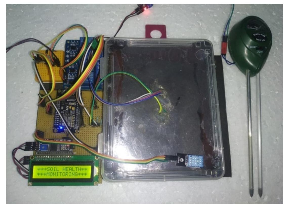
Figure 2 – uploaded by IJRASET Publication

Figure 2 Before conducting the soil test measurement, the transducer was initially optimized by varying the distance between LED, reflector and LDR sensor module. During measurement, the LED and the LDR was positioned in parallel facing both in the same direction. The light gets reflected by the reflector and gets detected by the LDR. The effect of the incident light Figure 2: Block diagram of proposed model emitted to the detector was investigated to determine an optimum optical path length of the transducer. The soil test absorption measurement was conducted using the developed optical transducer with four types of soils. Two types of the soils with different nutrient were obtained from a nursery shop while the other two were taken from residential areas. The sample specification is listed in TABLE II. Each of the soil samples with optimum thickness was placed on top of the reflector under the illumination of LED lioht


