JP3826598B2 - Image monitoring apparatus and recording medium - Google Patents
Image monitoring apparatus and recording medium Download PDFInfo
- Publication number
- JP3826598B2 JP3826598B2 JP02124199A JP2124199A JP3826598B2 JP 3826598 B2 JP3826598 B2 JP 3826598B2 JP 02124199 A JP02124199 A JP 02124199A JP 2124199 A JP2124199 A JP 2124199A JP 3826598 B2 JP3826598 B2 JP 3826598B2
- Authority
- JP
- Japan
- Prior art keywords
- monitoring
- image
- storage area
- video
- time
- Prior art date
- Legal status (The legal status is an assumption and is not a legal conclusion. Google has not performed a legal analysis and makes no representation as to the accuracy of the status listed.)
- Expired - Fee Related
Links
Images


Classifications
-
- H—ELECTRICITY
- H04—ELECTRIC COMMUNICATION TECHNIQUE
- H04N—PICTORIAL COMMUNICATION, e.g. TELEVISION
- H04N5/00—Details of television systems
- H04N5/76—Television signal recording
- H04N5/765—Interface circuits between an apparatus for recording and another apparatus
-
- H—ELECTRICITY
- H04—ELECTRIC COMMUNICATION TECHNIQUE
- H04N—PICTORIAL COMMUNICATION, e.g. TELEVISION
- H04N7/00—Television systems
- H04N7/18—Closed-circuit television [CCTV] systems, i.e. systems in which the video signal is not broadcast
-
- H—ELECTRICITY
- H04—ELECTRIC COMMUNICATION TECHNIQUE
- H04N—PICTORIAL COMMUNICATION, e.g. TELEVISION
- H04N5/00—Details of television systems
- H04N5/76—Television signal recording
- H04N5/91—Television signal processing therefor
- H04N5/93—Regeneration of the television signal or of selected parts thereof
-
- H—ELECTRICITY
- H04—ELECTRIC COMMUNICATION TECHNIQUE
- H04N—PICTORIAL COMMUNICATION, e.g. TELEVISION
- H04N21/00—Selective content distribution, e.g. interactive television or video on demand [VOD]
- H04N21/40—Client devices specifically adapted for the reception of or interaction with content, e.g. set-top-box [STB]; Operations thereof
- H04N21/43—Processing of content or additional data, e.g. demultiplexing additional data from a digital video stream; Elementary client operations, e.g. monitoring of home network or synchronising decoder's clock; Client middleware
- H04N21/431—Generation of visual interfaces for content selection or interaction; Content or additional data rendering
- H04N21/4312—Generation of visual interfaces for content selection or interaction; Content or additional data rendering involving specific graphical features, e.g. screen layout, special fonts or colors, blinking icons, highlights or animations
- H04N21/4316—Generation of visual interfaces for content selection or interaction; Content or additional data rendering involving specific graphical features, e.g. screen layout, special fonts or colors, blinking icons, highlights or animations for displaying supplemental content in a region of the screen, e.g. an advertisement in a separate window
-
- H—ELECTRICITY
- H04—ELECTRIC COMMUNICATION TECHNIQUE
- H04N—PICTORIAL COMMUNICATION, e.g. TELEVISION
- H04N21/00—Selective content distribution, e.g. interactive television or video on demand [VOD]
- H04N21/40—Client devices specifically adapted for the reception of or interaction with content, e.g. set-top-box [STB]; Operations thereof
- H04N21/47—End-user applications
-
- H—ELECTRICITY
- H04—ELECTRIC COMMUNICATION TECHNIQUE
- H04N—PICTORIAL COMMUNICATION, e.g. TELEVISION
- H04N5/00—Details of television systems
- H04N5/76—Television signal recording
- H04N5/765—Interface circuits between an apparatus for recording and another apparatus
- H04N5/77—Interface circuits between an apparatus for recording and another apparatus between a recording apparatus and a television camera
-
- H—ELECTRICITY
- H04—ELECTRIC COMMUNICATION TECHNIQUE
- H04N—PICTORIAL COMMUNICATION, e.g. TELEVISION
- H04N5/00—Details of television systems
- H04N5/76—Television signal recording
- H04N5/765—Interface circuits between an apparatus for recording and another apparatus
- H04N5/775—Interface circuits between an apparatus for recording and another apparatus between a recording apparatus and a television receiver
-
- Y—GENERAL TAGGING OF NEW TECHNOLOGICAL DEVELOPMENTS; GENERAL TAGGING OF CROSS-SECTIONAL TECHNOLOGIES SPANNING OVER SEVERAL SECTIONS OF THE IPC; TECHNICAL SUBJECTS COVERED BY FORMER USPC CROSS-REFERENCE ART COLLECTIONS [XRACs] AND DIGESTS
- Y10—TECHNICAL SUBJECTS COVERED BY FORMER USPC
- Y10S—TECHNICAL SUBJECTS COVERED BY FORMER USPC CROSS-REFERENCE ART COLLECTIONS [XRACs] AND DIGESTS
- Y10S707/00—Data processing: database and file management or data structures
- Y10S707/99931—Database or file accessing
- Y10S707/99932—Access augmentation or optimizing
-
- Y—GENERAL TAGGING OF NEW TECHNOLOGICAL DEVELOPMENTS; GENERAL TAGGING OF CROSS-SECTIONAL TECHNOLOGIES SPANNING OVER SEVERAL SECTIONS OF THE IPC; TECHNICAL SUBJECTS COVERED BY FORMER USPC CROSS-REFERENCE ART COLLECTIONS [XRACs] AND DIGESTS
- Y10—TECHNICAL SUBJECTS COVERED BY FORMER USPC
- Y10S—TECHNICAL SUBJECTS COVERED BY FORMER USPC CROSS-REFERENCE ART COLLECTIONS [XRACs] AND DIGESTS
- Y10S707/00—Data processing: database and file management or data structures
- Y10S707/99931—Database or file accessing
- Y10S707/99933—Query processing, i.e. searching
Landscapes
- Engineering & Computer Science (AREA)
- Multimedia (AREA)
- Signal Processing (AREA)
- Closed-Circuit Television Systems (AREA)
- Television Signal Processing For Recording (AREA)
Description
【0001】
【発明の属する技術分野】
本発明は、監視映像分野で使われる映像記録装置に関わり、長時間記録した監視映像を録画時間の数十分の一で閲覧・検索が可能な画像記憶装置の提供にある。
【0002】
【従来の技術】
スーパーマーケットやコンビニエンスストア、エレベータなど、頻繁に人の出入りがありながら、そこを管理・維持する側のスタッフの目が届きにくい箇所には、防犯・検挙を目的とした監視カメラが設置されている。こうした監視システムには、集められた映像を人間に見張らせる形態(オンライン監視と呼ぶことにする)と、映像を蓄積しておいて事後必要な場合(犯罪発生等)に閲覧検索をする形態(蓄積型監視と呼ぶことにする)の大きく2つが在る。蓄積型監視の形態は、オンライン監視に比べて人件費がほとんどかからないため、広く利用されている。この蓄積型監視では、取得された映像の蓄積に、主としてタイムラプスビデオレコーダが使われる。
【0003】
タイムラプスビデオレコーダとは、通常のビデオカムコーダを基に、数百時間分の映像を蓄積できるよう、通常秒当たり30回行うフレーム画像録画の間隔を1秒間に数フレーム程度からに広げて、散発的に映像を記録できるように改変したものである。一般的なビデオカムコーダベースのタイムラプスビデオレコーダでは、120分録画可能なテープメディアを使って1フレーム/秒で録画することにより約180時間(約8日間分)の記録が可能である。フレーム録画の間隔を広げればさらに長時間の記録が可能であるが、監視対象が記録映像から欠落してしまう危険があるために実際の運用上は1秒以上間隔を広げることはほとんどない。また、120分以上の記録時間を持つテープメディアを使うことも可能であるが、テープメディアの耐久性(破断)の問題があるため120分テープが使われる。こうした状況から、ビデオカムコーダベースのタイムラプスビデオレコーダの最長録画時間はほぼ180時間となっている。映像記録はテープの先頭から終わりに向かって順に行われる。テープの終わりまで記録すると、自動的に巻き戻しを行い、テープの先頭から上書きを行って行く。このようにして、常に最大180時間前までの映像を蓄えるようになっている。映像の閲覧方法は、通常のビデオカムコーダとほぼ同じである。ただ、そのまま普通に録画されたビデオテープと同じように再生すると30倍速になってしまうので、秒数枚の割合でも再生できるようになっている。
【0004】
また、一部のタイムラプスビデオレコーダでは、記録方式をデジタル化しハードディスク上に記録するものもある。これは、VHSビデオカムコーダベースのタイムラプスビデオレコーダでは、機械的に記録・停止を繰り返してテープヘッドが故障したり、再生時にテープメディアが劣化したりといった問題点を解決するものである。こうしたデジタル記録方式を採用したものは、従来のテープメディアに記録する方式のものと区別してデジタル・タイムラプス・ビデオレコーダと呼ばれる。
【0005】
このようにタイムラプスビデオレコーダでは長時間の蓄積が可能であるが、蓄積した映像の再生・閲覧には大きな問題があった。まず、第一に、180時間分すべてを確認するのに記録メディアの持つ録画時間(テープでは120分)の数倍の時間がかかってしまうという点である。第二に、監視映像として意味のあるものと無いものが同時かつ交互に、記録・再生されており、探すべき箇所の整理がされない状態で検索・閲覧を行うため、非常に効率が悪いという点である。現状では、テープ先頭から単純に再生を行い、漠然とした閲覧を行わざるを得ないため、目的とする映像を見落としやすい状況になっている。
【0006】
以上のように、タイムラプスビデオレコーダでの蓄積映像の閲覧では、長時間に渡って映像の判別に集中することが求められ、ユーザの苦痛となっていた。
【0007】
これに対し、赤外線センサのような人感センサと組み合わせるアプローチが既にあり、解決が可能であるように思われるが、(1) VHSビデオカムコーダベースのタイムラプスビデオレコーダでは、録画・停止操作を行う機械部分が頻繁なオンオフによって故障率が激増する、(2) 人感センサの有効距離やセンサの感度の点で信頼性が乏しい、(3)新たな設置コストがかかる、などの問題点から、実際のタイムラプスビデオレコーダの運用ではほとんど使われておらず、問題の解決には至っていなかった。
【0008】
従来のタイムラプスビデオレコーダにおける根源的な問題点は、入力される映像を何ら分類すること無く、単に時間順で蓄積することにある。もし、人間が直接監視を行なってメモをとるのであれば、監視場所に生ずる変化(例:人の出入り、備品配置の変化など)に合わせて分類・整理を行なうなどして後で探しやすくするであろう。また、閲覧の場合にも、探したい内容(例:侵入者の顔映像、備品の破壊・盗難の有無)に合わせて、要求に合いそうな部分だけを大まかに取り出しておいて、そこからじっくり探すといった工夫を施す。監視を行なう時間が長くなればこうした工夫はいっそう重要である。
【0009】
タイムラプスビデオレコーダでも、先に述べたような人間が行なっている整理・分類・絞込みを行なうことができれば、これまで検索にかかっていた時間を大幅に減らすともに、ユーザにかかる精神的な負担を著しく低減することが可能になる。
【0010】
【発明が解決しようとする課題】
以上のように、従来の画像記憶装置(タイムラプスビデオレコーダ)は、映像を分類・整理して蓄積する方式と、目的とする映像を探すための閲覧方式に関して問題があった。
【0011】
本発明が解決しようとする課題は、監視対象となる場所に生ずるさまざまな監視イベント(人の出入り、顔が映っているかどうか、環境の物理的変化など)を検出し、そのイベントの種類に応じて映像を分類・整理して蓄積し、ユーザが閲覧・検索する際に要する時間を大幅に短縮するインターフェイスを備えた、画像記憶装置、監視システム、監視方法が記録されたコンピュータ読みとり可能な記録媒体の提供にある。
【0012】
【課題を解決するための手段】
上記の課題を解決するため、
時系列に画像を入力してディジタル化する手段と
現在入力中の画像を表示する入力画像手段と
入力画像に対して監視イベントを検出する監視イベント検出手段と
検出した監視イベントに基づいて入力画像を記憶するか判定する録画判定手段と録画判定手段で「録画する」と判定された画像を記憶する画像記憶手段と
記憶した画像の格納場所と、検出された監視イベント情報を記録する監視イベント記憶手段と
ユーザの閲覧要求を満たす監視イベント情報を検索し閲覧する画像を選別し、監視イベント情報とともにレイアウトする画像選別配置手段と
レイアウトされた画像または監視イベント情報をひとつまたは複数表示する監視情報表示手段と
を具備する。
【0013】
上記の画像記憶手段ならびに監視イベント記憶手段の媒体には、ハードディスク、DVD-RAM、フラッシュメモリのランダムアクセスメモリを用いる。
【0014】
上記の監視イベント検出手段は、特開平8−221577「移動物体検出・抽出装置」に公開されている手法により、サンプリング時刻時の入力画像と過去に録画した画像間の相異度から、背景構造変化の有無、照明変化の有無、移動物体の有無などをそれぞれ監視イベントとして検出する。また、肌色領域を検出することにより、移動物体が存在するシーン中に顔の候補領域が存在するかどうかを判定することにより、「顔がカメラ側に最も向いた時点」という監視イベントを検出する。
【0015】
上記の録画判定手段手段は、最新の監視イベントと、既に検出されている監視イベントの種類・履歴と、直前に記憶した画像の録画時刻との現在時刻との差、各種記憶手段に用いられている媒体の残り容量、ユーザが指定した最小記憶時間長などから、画像を「録画する」かどうかを判定する。
【0016】
上記の監視イベント記憶手段は、これら監視イベントについて録画すると判定された場合に、装置内の画像が格納される場所、発生・終了した日時・フレーム映像中での位置・カメラID(場所ID)と、監視イベントを表す特徴量を所定の場所に記憶する。
【0017】
上記の画像選択配置手段は、例えば、「検知された顔画像の一覧」、「ある1時間内に発生した監視イベントの一覧」、「在る監視イベントで録画された画像のアニメーション表示」、「監視場所の設置物の変化時のみの一覧」、「一日の監視イベントの分布」、などのユーザの閲覧要求ごとに、監視イベント情報を検索し、対応する画像を選択・配置して、ユーザが見やすいようなビューを作成する。なお、各ビュー毎の画像選択・配置に必要な、検索対象やレイアウトに関するルール・アルゴリズムはあらかじめ装置のファームウエアとして内蔵する。
【0018】
さらに別の解決手段では、上記装置に、
複数表示された画像または監視イベント情報をユーザの閲覧操作に従って同期させる手段
を追加することにより、複数のビューが連携して表示されるインターフェイスを実現し、ユーザに、監視イベント情報と画像を多角的・効率的に提示する装置を実現する。
【0019】
【発明の実施の形態】
以下、本発明の1実施例を詳細に説明する。
【0020】
図1は、本発明の画像記憶装置を利用した監視システムの一例である。監視カメラ200からの映像信号は、画像記憶装置100のビデオ入力端子110から入力され、ディジタル画像として記録される。記録されたディジタル画像はビデオ出力端子110からアナログ画像としてデイスプレィ210に表示される。また記録されたディジタル画像はLAN端子140からWANを通して監視センタのパソコン220へ送られる。その際、電話回線なども利用可能である。画像記憶装置100は、タッチパネル130とポインティングデバイス190を介した指示によって制御される。
【0021】
以上のように本発明の画像記憶装置100に接続される監視機器は、従来のアナログの監視カメラやディスプレイがそのまま接続可能である。さらに、ネットワークを介して遠方に監視映像を伝送できる点は、従来のタイムラプスビデオレコーダになかった機能である。
【0022】
図2は、本発明である画像記憶装置のシステム構成の一例である。基本的には、現在汎用的に用いられているデジタルコンピュータのシステム構成と同じである。
【0023】
まず111は監視カメラからの映像信号をディジタル画像に変換するA/D変換器である。変換されたディジタル画像はインタフェース112を介してメモリ170に取り込むと同時にビデオメモリ118に取り込まれる。
【0024】
ビデオメモリ118はディスプレイ210に表示される画像をディジタルデータとして格納する。119は、一般にRAMDACとも呼ばれている種類のD/A変換器であり、ビデオメモリ118に書かれたデータを走査線スピードに合わせて逐次読みとり、ディスプレイ210に描画する。したがって、ビデオメモリ118のデータを更新すると、その更新内容がディスプレイ210の表示内容に直ちに反映される。ディスプレイ210は、画像を表示するためのデバイスであり、例えば、小型のCRTやプラズマディスプレイであっても良いし、液晶タイプの表示デバイスであっても構わない。
【0025】
こうした画像の取り込みを、秒30回程度の頻度で繰り返すことで、ディスプレイ上で連続的な動画の表示が行える。
【0026】
補助記憶装置160は、ハードディスク等の大容量記録装置であり、ディジタルデータを半永久的に記録するための装置である。これは、PCMCIAタイプのハードディスクカードのように記憶装置ごと本体から着脱できるものであったり、あるいは、DVD-RAM、フラッシュメモリ等のように、記録媒体のみを着脱できるタイプの記録装置であっても構わない。
【0027】
CPU150は、監視イベントの検出、録画制御、表示画像の選択・配置など、本発明で説明する機能を実現するためのソフトウエアプログラムを実行する。プログラムは、メモリ170に常駐し、プログラムの実行に必要となるデータもここに必要に応じて格納される。
【0028】
NIC(Network Interface Card)139は録画した画像や監視イベント情報をネットワークを通じて伝送する。赤外線受光部130はリモコンからの情報入力デバイスである。
【0029】
ユーザからの指示は、タッチパネル130からインタフェース131を介して、CPU150に伝えられ、適宜処理される。
【0030】
180は、以上述べた各デバイス間を相互につなぐデータバスである。
【0031】
以上の画像記憶装置のシステム構成において、
まず、監視映像を記録する際の動作について説明する。
【0032】
記録動作は、メモリ170内に格納された制御プログラム171によって制御される。最初に、ビデオ入力端子110から映像を取り込んで個々のフレーム画像の列とし、メモリ170に格納する。同時に、逐次ビデオメモリ118に転送し、ディスプレイ210に入力画像を表示する。次に、メモリ170に格納されたフレーム画像列から監視イベントを検出し、これをメモリ170に格納する。この監視イベント情報と制御データ172から、録画すべき画像だけを判定・選択する。最後に、監視イベント情報と選択された画像を補助記憶装置160に格納する。
【0033】
次に、監視映像がユーザによって閲覧される際の動作について説明する。閲覧時の動作は記録時と同様、メモリ170内に格納された制御プログラム171によって制御される。まず、タッチパネル130を介して入力されたユーザの閲覧要求に従って、補助記憶装置170に格納されている監視イベント情報をメモリ170上に転送する。この際、監視イベント情報の内部レコードを読んで、要求に一致しないものをメモリから削除する。次に、選別された監視イベント情報の内部レコードを読んで、監視イベントに対応する画像のパス名を取得し、該当する画像を補助記憶装置160からメモリ170に転送する。次に、メモリ170上の監視イベント情報と画像をユーザに見やすい形態にレイアウトし、ビデオメモリ118に転送する。ビデオメモリ118に転送された監視イベント情報と画像データは監視結果としてそのままディスプレイ210に表示される。以上の動作を、ユーザからの入力指示に応じて何度も繰り返す。
【0034】
一般にタイムラプスビデオレコーダでは、映像を録画する際のサンプリング間隔は自由に設定できるようになっており、間隔を大きくする事でより長時間の録画ができるようになっている。しかし、単純にサンプリング間隔を拡げすぎると、カメラのフレーム映像中を通過する物体が速い場合に録画漏れが生じ、監視の目的が達成できなくなってしまう。そこで、録画漏れを生じさせること無く、長時間録画が可能な方式を以下に説明する。
【0035】
図3、4、5は本発明で検出した監視イベントに従って映像を記録する方式を示す図である。
【0036】
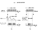
図3は、従来の単純なタイムラプス録画に監視イベントによるフィルタリングを組み合わせた記録方式を説明する図である。
【0037】
300はビデオ信号の生成周期を示すタイミングチャートである。NTSC規格では1秒間に30フレームが生成される。これに対して、指定したサンプリング間隔で画像を取り込むことで時間的にフレームを間引く。
【0038】
310はサンプリングのタイミングチャートを示す。この例では時間的にフレームを30分の1に間引き、1秒に1フレームだけ取り込むようにしている。
【0039】
320はサンプリング時の画像内容を表している。監視カメラが固定してあり、侵入物や背景の変化がない場合(320‐2)、すなわち監視イベントが生じていない場合、入力画像列はほとんど同一となる。そこで、「監視イベントが生じていない=前回録画した画像と現在録画しようとする画像が同じである」と判定された場合は録画を省略することで録画のためのメモリ消費を省く。
【0040】
330は選択されたフレームを示す。このように監視イベントによるフィルタリングを行うと、画像の変化の多い時間帯は一定のメモリ消費になるが、夜間など変化が少なくなると、冗長な録画によるメモリ消費が少なくなり、長時間の録画が可能になる。録画が省略された時間の画像はその一つ前に録画された画像と同じであるので、録画が省略された時刻の画像検索要求があっても、代理の画像で結果を表示することが可能となる。
【0041】
録画データ161とそれが取得された時刻情報を含む監視イベント情報162から構成されているので、図3の例では、「時刻1の画像を表示せよ」との検索要求があった場合、時刻0の画像を代理で表示することができる。
【0042】
図4は、図3とは別の方式による映像記録方式について説明するものである。
【0043】
340はサンプリングのタイミングチャートを示す。図3はサンプリング間引きを行なった後に監視イベントを判定するものであるが、図4では、サンプリング間引きをせずに直接入力されたビデオ映像の全フレームから監視イベントの検出を行ない、イベント区間を決定した後に、例えば、3秒に1回等の、あらかじめ指定されたサンプリング間隔で記録を行なう。サンプリングの間隔を入力と同じ1/30秒とすれば、イベント発生時の入力映像を記録することができる。
【0044】
この方式は、監視カメラ中の移動物体の運動方向などを監視イベントとして検出したい場合や、下記(III)に述べる動的な録画間隔の制御を行なう場合に適している。
【0045】
図5は、動的な録画間隔の制御を行なう方式を説明するものである。
【0046】
350、360はサンプリングのタイミングチャートを示す。
【0047】
この記録方式の基本的な大枠は図4と同一であり、サンプリング間引きをせずに入力ビデオ映像の全フレームから監視イベントを検出・記録を行なう。図4と異なる点は、記録の際のサンプリング間隔が固定であったのに対し、図5ではサンプリング間隔を動的に変更する点である。タイミングチャート350では、監視イベント情報とサンプリング間隔をリンクさせて記録を行なう方式を示したものである。
【0048】
例えば、監視イベントとしてフレーム映像の変化を検知する。最新のフレーム画像と直前のフレーム画像について各画素の差分絶対値をそれぞれ求めて総和を計算する。この値はカメラ映像中で動くものが多い時や動きの激しいときに大きくなり、動きが小さいときにはほぼゼロになるという性質を持っている。
【0049】
この性質を利用して、この値の大小に合わせて、値が小さいときにはサンプリング間隔を例えば、毎秒2から4回程度に広げ、値が大きいときにはサンプリング間隔を例えば、毎秒30回程度に狭めることにする。すると、記録される監視映像は、カメラ映像中で動くものが多い時や動きの激しい時にはほぼ動画に近い形となり、変化の小さい場合にはパラパラとアニメーションのように記録される。
【0050】
この方式では映像中の変化が一定範囲となるように記録することができ、例えば、人の動作を記録したい場合などには、一定の動き毎に記録を行うことができる。
【0051】
また、タイミングチャート360のように、あらかじめ作成したサンプリング間隔の制御ルールを与えることも有効である。例えば、外部から人が入室してくるドアを監視する場合、入室者の顔映像を記録できることが重要になる。この場合、監視イベント(映像変化)を検出し、記録をはじめた直後はサンプリング間隔を密にし、徐々に間隔を広げて行くように設定する、これによって、顔が映ったフレーム画像を確実に録画することが可能になる。
【0052】
以上のように本発明によれば、監視イベントによって、録画実行の判定と録画間隔の制御を行なっているので、動作や顔といった監視したい対象の録画漏れを生じさせることなく、長時間の録画を可能にする。
【0053】
図6、7、8は、本発明の監視映像記録装置における映像録画・再生時の画面を説明するものである。これらの出力はタッチパネル130が被せられたディスプレイ210上に表示されるものである。
【0054】
図6は、映像録画時の画面である。基本的には、現在入力されている映像を表示する領域400が中心となって構成される。入力映像領域400には、場所・日時などの監視イベント情報表示401や、監視イベントが現在検知されていることと録画が行なわれていることを示すマーカー402が重畳表示され、ユーザにシステムの動作が一目でわかるようになっている。403は、システムが映像監視を開始するかどうかを制御するボタンである。
【0055】
監視イベント情報表示401には、カメラが映している場所を示すID(監視場所の名称:あらかじめユーザによって登録される)、年月日、タイムコード(時分秒とその秒内でのフレーム番号)などが含まれる。
【0056】
マーカー402による、監視イベントの検出状態と録画状態をユーザへ通知方法であるが、例えば以下のように動作する。システムが、監視イベントを検出しはじめると、黄色で点滅をはじめる。録画時には一瞬赤く点滅することによって補助記憶装置160への録画(画像データと監視イベント情報データの転送)が発生していることを通知する。
【0057】
410は、検出した監視イベントの履歴をユーザに通知する領域である。ここには、監視イベント情報の有無や強度(例:フレーム差分値など)を示す波形グラフ411が表示される。波形411は時間遷移に従って順次左方向にシフトし、表示領域410の右端に最新の監視イベント情報値が波形値として追加される。表示領域410下部には波形データ411の全体的な時間分布がわかるように、時刻を表す表示412がおかれる。本例では、現在時点からの何分前かを表示しているが、絶対時間(何時何分であるか)を表示しても良い。
【0058】
420もまた、検出した監視イベントの履歴をユーザに通知する領域である。ここには、これまでに検出された監視イベント毎の代表画像421と時刻422が表示される。本例では、表示領域420の上部に最新の監視イベントに対応する画像が表示され、以下下に向かって新しい順に代表画像421と時刻422が配置されている。
【0059】
表示領域410・420は、ポインティングデバイス190等により、グラフ部分や画像部分をタッチするにより、録画映像の再生が可能になっている。
【0060】
再生時には、後述する図7のように領域400部分の表示に切り替わり、そこに録画した映像が出力される。
【0061】
例えば、領域420上の代表画像部分をタッチすることにより、該当する監視イベントの発生した区間の一連の画像データ161を補助記憶装置160から読み出して、領域400上に表示再生する。また、領域410の波形グラフ部分をタッチすると、該当時間に最も時間的に近い監視イベント区間の映像を領域400上に再生する。これに同期して、表示した監視イベントとその前後のイベントの代表画像を領域420上に表示する。このとき、タッチした箇所がユーザにフィードバックされるようにグラフ上に異なる色の縦線が表示される。
【0062】
なお、本例では、記録時画面内に記録映像と再生映像の表示を行なう領域400とそれ以外の領域410、420を併置しているが、これらは表示領域400と別々に表示しても良い。
【0063】
図7は再生時の画面について説明するものである。再生時には、領域400の上部と下部にそれぞれ再生操作に適したボタン類が新たに表示される。これらのボタン類はディスプレイ210上に表示される図とタッチパネル130の組み合わせによって実現されている仮想的なボタンである。これらボタン類にポインティングデバイス190などでタッチすることにより、ボタンを押したことに相当する動作をシステムが行なう。
【0064】
領域400には再生される映像が、記録時の入力映像と同様に表示される。
【0065】
401には再生している映像に対応する監視イベント情報が表示される。
【0066】
監視イベント検出マーカー402は再生時にも表示されうる。後述するが、本発明では再生時にもバックグラウンドで記録を行なうことが可能となっている。例えば、ユーザが監視映像を記録している間に、記録した映像を再生しようとする場合、マーカー402が表示されて、ユーザが閲覧している間にも監視イベントの検出があったことを通知する.もちろん、バックグラウンドで録画を行なっていない場合には、マーカー402は表示されない。
【0067】
430は図6の記録時画面へ戻るためのボタンである。
【0068】
431は現在再生している監視イベント映像の内、イベント区間に含まれるフレーム画像データの総数と現在表示されている画像が何フレーム目であるかをユーザに通知する。
【0069】
432は再生映像の再生、一時停止、逆再生、こま送り等を制御するボタンである。
【0070】
433は後述する図8の代表画像一覧画面に遷移するためのボタンである。
【0071】
図8は検出した監視イベント毎の代表画像の一覧を表示する画面である。基本的には図6における表示領域420と同じであり、横方向にも幅を広げてラスタースキャン順に代表画像421と時刻422を並べて表示したものである。
【0072】
上下に三角形の形状で配置されているボタン440は一覧表示の内容を時間方向に従って切り替える。上部のボタンを押すと、時間的に一表示単位分前の内容を現在のページに表示する。下部のボタンを押すと一表示単位分後ろの内容を表示する。ユーザの操作によって、記録されている監視イベントの最初や最後まで到達した場合には、進めない方向のボタンが薄い色で表示され、ボタン入力を受け付けなくなる。
【0073】
ユーザが個々の代表画像421にタッチ・選択を行なうと、図7で説明した再生画面に切り替わり、選択した監視イベント区間の映像が再生される。
【0074】
図9は、画像記憶装置100を監視センタのような遠隔地から操作し、記録を行なったり、監視映像を再生・閲覧するユーザインターフェイスについて説明するものである。
【0075】
本実施例では、画像記憶装置100に対して、遠隔地にあるパソコン220から制御・閲覧を行なうために、それぞれWEBサーバとWEBブラウザを用いている。後述するが、画像記憶装置100側にWEBサーバを内蔵させ、遠隔地にあるパソコン220のWEBブラウザ上に示されるWEBページ500を表示する。以下、このページの説明を行なう。
【0076】
メニュー510、ブラウズボタン520、URL表示部530、ブラウザステータス表示部580は、監視情報ページ500を表示するWEBブラウザの制御用ユーザインターフェイスの一部である。
【0077】
この監視情報ページ500は、上記のブラウザコンポーネントのほか、監視データの最新時刻を表示する領域540、監視場所毎に年月日/日時で監視イベントをツリー表示した領域560、指定された日時毎の監視イベントについて、その代表画像を一覧表示する領域570、ツリー表示領域560または一覧表示領域570で選択された監視イベント区間の映像を再生表示する領域550、の大きく4つの表示領域から構成される。
【0078】
領域540は、現在表示中の監視データがいつの時点のものかをユーザに示す。これは、WEBのような形態の対話では、常に最新の情報をサーバからブラウザ側に送りつづけることが一般には困難である。すなわち、ある特定の時刻から遡った静的な状態でしかブラウザに提示できないからである(WANなどの途中のネットワーク帯域が十分でないことや、通信回線を維持するコストの問題、サーバ・クライアントの両方に生ずるCPU負荷が大きいなど)。従って、画像記憶装置100が監視映像を記録中に、遠隔地から監視結果をブラウザ経由で閲覧する場合、ページの内容が画像記憶装置100の内部に蓄積された状態と異なることがしばしば生ずることとなり、ユーザにその時間差を意識させる必要が生ずるためである。
【0079】
領域560は、監視場所毎に年月日/日時で監視イベントをツリー表示することによって、ユーザがあらかじめ閲覧したいと思う場所、日時にすばやく到達することができるインターフェイスを提供する。ツリー表示は、上から順に、場所561、年月日562、時563、監視イベント単位564の4階層で構成される。ツリーの各ノードのアイコンをマウスでクリックすると、下位ノードが表示されていない場合には、アイコンが開いたイメージのものに替わり、下位ノード表示を行なう。逆に、表示されている場合には、アイコンが閉じたイメージのものに変わり、下位ノードを隠すといった動作を行なう。これにより、ユーザは目的とするノードだけを常に開いて閲覧することができる。
【0080】
各ノードのテキスト部分565をクリックすると映像再生表示領域550や一覧表示領域570の表示内容が変化する。例えば、場所561、年月日562、時563の上位3階層のノードについて、そのテキスト部分565をクリックすると、その範囲での最も新しい年月日/時刻の監視イベント一覧が領域570に表示される。
【0081】
最も下位のノードである、監視イベント単位564のテキスト部分をクリックすると今度は、映像再生表示領域550に、該当する監視イベント区間の録画映像を再生する。
【0082】
570は、図6における420と同様、指定された時刻に含まれる、検出した監視イベント毎の代表画像の一覧を表示する領域である。領域上には、一覧表示している場所と年月日の表示571と時刻毎の区切りを示す時刻表示572、代表画像573が配置される。ブラウザ起動時など、時刻を与えることができない場合には、最新の記録日時に含まれる代表画像の一覧を表示する。
【0083】
代表画像572をクリックすると、映像再生表示領域550上に該当する監視イベント区間の録画映像を再生する。
【0084】
従来のタイムラプスビデオレコーダでは、監視結果を再生する際に、単に時間順に提示するだけであったため、きわめて時間がかかっていた。
【0085】
これに対し、図6〜9で述べてきたユーザインターフェイスを用いることにより、時間構造に合わせて階層的に提示したり、内容を判定しやすい代表画像でタイル状に二次元配置して提示することができる。
【0086】
ツリー表示は従来では不可能であった目的日時への高速なアクセスが可能であり、またすぐに映像を再生できるので、大体の当たりをつけた検索を行なう場合に非常に効果を発揮する。また、二次元配置は一度に複数の監視イベントをざっと見渡すことを可能にし、パラパラと見るときに必要とする時間を大幅に短縮することを可能にする。
【0087】
これらにより、従来のタイムラプスビデオレコーダでは不可能であった、高速な閲覧と監視映像の内容の効率的な確認が可能になる。実際、われわれのフィールドテストでは検索に要する時間を1/30〜1/100程度に低減できることが確認されている。このように、本発明は従来の監視映像記録機器に比べて、使い勝手が良く省時間効果の高いインターフェイスを提供する。
【0088】
図20は、画像記憶装置100について、機能の観点から構成を説明するものである。主たる構成要素は、メインコントロール610、監視イベント検出エンジン620、ビデオ出力用表示プログラム630、HTML生成プログラム640、WEBサーバ650の5つである。
【0089】
メインコントロール610は、制御プログラム171の主たる機能そのものであり、画像記憶装置100全体を制御する。具体的には、タッチパネル130やWEBサーバ650経由でシステムへのユーザ入力をハンドルし、監視イベント検出エンジン620、ビデオ出力用表示プログラム630、HTML生成プログラム640、WEBサーバ650の動作を制御する。
【0090】
監視イベント検出エンジン620は、あらかじめ登録されている監視イベントを監視カメラ200から入力された映像信号から検出し、その監視映像データ161と監視イベント情報データ162を補助記憶装置160に格納する。
【0091】
ビデオ出力用表示プログラム630は、図6で説明した画面を出力・表示する。タッチパネル130を経由してメインコントロール610に伝えられた、ユーザからの入力に応じて監視映像データ161と監視イベント情報データ162を補助記憶装置160から読み出して、画面上に映像や関連する監視イベント情報を表示する。
【0092】
HTML生成プログラム640は、図9で説明した監視映像のWEBページ出力用にHTMLを動的に作成する。まず、パソコン220上で行なわれたユーザ操作はWEBページ500からWEBサーバ650を経由してメインコントロール610に伝えられる。ユーザ要求に従い、監視映像データ161と監視イベント情報データ162を補助記憶装置160から読み出して、あらかじめ用意されたHTMLデータ中に監視イベント情報と画像のWEBサーバ上での位置を示すHTMLタグを書き出す。これにより、HTMLの動的生成を実現する。
【0093】
WEBサーバ650はこうして作成されたWEBページを遠隔地側のパソコン220に配信するとともに、ユーザからの操作命令をメインコントロール610に伝える。
【0094】
図11、12、13は、監視イベント検出エンジン620で実行される監視イベント検出の方法について説明するものである。
【0095】
ここでは、移動物体の有無を例として述べる。
【0096】
まず、入力される映像から個々のフレーム画像700を取り出す。次に、図11に示すようにフレーム画像を複数の小矩形領域710にわけ、個々の領域毎に映像変化の有無を検出する。
【0097】
映像変化の判別方式としては例えば(特開平8−221577「移動物体検出・抽出装置」)に記述されている方式を用いる。この方式では、個々の着目領域710ごとに背景・移動物体・背景構造変化・照度変化を検出できる。
【0098】
以下、個々の領域で用いられる移動物体検出方式について簡単に説明する。
【0099】
まず、フレーム画像上の着目領域の内、移動物体の存在しない時刻を選んでこれを背景画像とする。
【0100】
そして、この背景画像と毎回新たに入力される最新の画像との間で、画像の相違度を計算する。この相違度計算の具体例としては、対応する位置の各画素の明るさについて差を求め、画像全体についてそれらの2乗和を求めてもよいし、明るさの替わりにRGBそれぞれの値の差分二乗和としてもよい。
【0101】
こうして得られた相違度を時間順に並べ、連続するグラフとして眺めてみると、移動物体が存在する時間区間は大きく変動する状態となる。移動物体が存在しない時間区間では変動の少ない平坦な状態となるが、背景として決めた時刻と背景が全く同一の場合場合、すなわち、画像的に内容が同じには、その区間の平均値はほぼ零となる。一方、物が置かれたりするなど、背景の構造が変わった場合には、画像的に内容が異なるために、平坦ではあるが区間平均値は一定の大きさ以上となる。
【0102】
この性質を用いることにより、時間区間として、移動物体の有無や、背景構造の変化の有無を確認することが可能となる。ここで問題になるのが、最初にどうやって背景となっている時刻を決定するかであるが、まず、任意の時点の画像を適当に選んで、相違度の時間変化グラフを求め、平らな区間が見つかった時点を開始とすればよい。その後の処理でも、背景構造の変化が有る時、すなわち、グラフの形状が平坦かつ一定値以上の平均値となる時のみ、背景とする時刻を更新するようにすれば、安定してこの処理を繰り返すことが可能になる。
【0103】
以上説明した方式により、フレーム画像上に設定した個々の着目領域について移動物体の存在する領域を色づけ(レベル付け)したとすると、図11の右側図のようになる。
【0104】
図12は、図11で説明した処理をすべてのフレーム画像について実行し、フレーム画像を時間順に並べてできる三次元の時空間画像について述べたものである。この時空間画像中では移動物体は部分的な立体720を構成する。これを図示したものが図12である。この時空間画像730を眺めると、「移動物体がある」という監視イベントは、ある程度の大きさを持った部分領域720があることとみなしても良い。これを別の観点から見たものが下のグラフである。1フレーム当たりの映像変化があった領域数をグラフ740としてみると、上記判定はグラフが一定値以上の区間750とみなすことができる。このようにして決定された区間を監視イベント「移動物体在り」の区間として判別する。そして、監視イベント情報162として、開始フレーム、終了フレーム、区間長、各領域毎の判定結果を補助記憶装置160に記憶する。
【0105】
なお、画像全体を一つの領域とみなして判定するのも一つの方法ではあるが、上記のように小領域で分割してその結果を統合する方が監視イベントのハンドリングに適している。例えば、小さな外乱などに対して検出エンジンの動作をロバストにすることができる。また、判定に含めない領域も容易に設定できたり、後述の検索処理や代表画面決定処理を簡単に記述できるなどの利点がある。
【0106】
他の監視イベント、例えば背景構造の変化(物の配置換えなど)や顔領域の出現等を検出する場合にも、上記のようにフレーム内の領域単位で検出を行なうことにより、安定した検出が可能となる。
【0107】
なお、本例では着目領域を矩形としたが、他のいかなる形状としても何ら問題無い。また、ここでは、領域をきれいに並べたが図13に示すようにオーバーラップを持たせ、領域毎の判別結果について論理演算を施すことにより、大きな領域で安定した判別を行ないながら、判別する領域の実効面積を小さくすることも可能である。
【0108】
図14は監視イベント情報162のデータ構造を説明するものである。
【0109】
監視イベント情報162はRDB(Relational Database:関係データベース)であり、場所テーブル162-1、画像テーブル162-2、イベントテーブル162-3、時間木テーブル162-4の4つのテーブルから構成される。
【0110】
場所テーブル162-1は、監視映像記録装置100が接続されたカメラの識別ID162-1-1と名称162-1-2、監視場所の名称162-1-3を格納するテーブルである。画像テーブル162-2の各レコードの冗長性をなくすために、独立して設けられている。
【0111】
画像テーブル162-2は、監視映像記録装置100に記憶された個々のフレーム画像を制御するためのテーブルである。フレーム画像ID162-2-1、場所ID162-2-2、録画年月日162-2-3、録画時分秒162-2-4、フレーム番号162-2-5、画像ファイルパス名162-2-6、イベント種類162-2-7、イベント属性データ162-2-8の項目から構成される。場所ID162-2-2は、場所テーブル162-1の場所ID162-1-2と同一の項目であり、実際のID番号が格納される。録画年月日162-2-3、録画時分秒162-2-4、フレーム番号162-2-5は、フレーム画像が記録された時の時刻情報である。一般的なRDBでは高速にハンドルできるデータ型として、年月日と時分秒がわかれていることが多いため、本実施例ではこれらを三つに分割してある。画像ファイルパス名162-2-6は、システム内に記録されている画像ファイルのパス名が格納されており、監視映像の再生や検索時に実際の画像データを読み出すのに用いられる。イベント種類162-2-7は、格納されたフレーム画像がどんな監視イベントにより格納されることになったかを示すフィールドである。複数の監視イベントが重なる場合を想定して、ビットフラグによって監視イベントの種類を示す。監視映像再生時や検索時に監視イベント毎のフィルタリングを施すために設けられている。イベント属性データ162-2-8は、監視イベント検出の根拠となった各領域毎の特徴量データを格納する領域である。
【0112】
イベントテーブル162-3は、監視イベントの区間情報をハンドリングする。イベントID162-3-1、開始フレームID162-3-2、終了フレームID162-3-3、代表フレームID162-3-4から構成される。開始フレームID162-3-2、終了フレームID162-3-3には、画像テーブル162-2のフレーム画像ID162-2-1が格納される。同様に、代表フレームID162-3-4は後述の代表画像決定アルゴリズムによって決定されたフレーム画像ID162-2-1が格納される。
【0113】
時間木テーブル162-4は、図9のツリー表示領域560などのように、監視イベント情報に対して、時間指定でダイレクトかつ高速にアクセスするために設けられたテーブルである。ノードID162-4-1、親ノードID162-4-2、ノード検索キー162-4-3、ノード内順序162-4-4、イベントID162-4-5、イベント種類162-4-6、場所ID162-4-7から構成される。このテーブルは冗長であるが、監視結果アクセス時のスループットを向上させるために設けられている。基本的には場所テーブル162-1、画像テーブル162-2、イベントテーブル162-3の3つから動的に作成可能であるが、監視映像の再生・閲覧動作では、きわめて高い頻度でこの計算が必要となるため、別にテーブルとして設けておくことによりシステムの負荷を小さくすることを目的としている。ノードID162-4-1、親ノードID162-4-2、ノード検索キー162-4-3、イベントID162-4-4、イベント種類162-4-5、場所ID162-4-6から構成される。ノードID162-4-1、親ノードID162-4-2はテーブルにより木構造を表現するためフィールドである。ノード検索キー162-4-3は、場所と年月日・時分秒から直接一番下位のノードにアクセスするための文字列であり、このテーブルをハッシュによって検索するための主キーとして設定されている。文字列であるため、キー作成が容易であり、検索のための計算コストが小さくてすむ。イベントID162-4-4は、イベントテーブル162-3のイベントID162-3-1と同一であり、実際のID番号が格納される。イベント種類162-4-5、場所ID162-4-6は、監視映像再生時や検索時に監視イベント毎のフィルタリングを施すために設けられたものである。
【0114】
なお、これらテーブルのデータ生成されるタイミングであるが、場所テーブル162-1は監視が開始される前にユーザによってあらかじめ作成されるものである。画像テーブル162-2とイベントテーブル162-3は実際の監視映像記録時に動的に生成されるデータである。時間木テーブル162-4もまた、記録時に生成されるデータであるが、これは画像テーブル162-2とイベントテーブル162-3の内容から副次的に生成されるものでもある。これは、先に述べたように監視結果アクセス時のスループットを向上させるために設けられているからである。
【0115】
以上のデータ構造により、画像記憶装置100は記録された監視イベントと映像を高速に検索・提示することが可能となる。また、図2、図10に示したハードウエア・システム構成と、この個々のフレーム画像ごとに独立したデータ構造により、監視映像を記録しながら閲覧を行なうという、これまでの監視記憶システムには不可能であったことをあらたに可能にしている。
【0116】
図15は、監視イベント区間における代表画面を決定するアルゴリズムについて説明するものである。
【0117】
画像記憶装置100が検出した監視イベントを420や500のように表示するケースを考える。移動物体有を示すイベントの場合、監視イベント区間を代表する画像としてどれを選ぶかは、監視結果の閲覧の効率を大きく左右する重要な点である。
【0118】
例えば、区間の先頭フレームを代表画像とすると、移動物体の一部だけが映るだけで、検出した移動物体に関する情報をほとんど提示できないことがしばしば起こる。これは、最終フレームであっても同様である。単純に先頭フレームと最終フレームの中間とすることも考えられるが、2つの移動体が連続して検出されて一つの区間となった場合には、ちょうど間のあまり両方が映っていないような画像が代表になってしまうという問題点が発生する。そこで、図5で述べたサンプリング間隔の制御に用いたのと同じ方法を使うことにする。
【0119】
監視イベントを検出するときに900のようなグラフが得られたとする。まず、顔領域の検出のようなケースで考えられるのが、グラフ値が最大となるフレーム910-4を代表画面とする方法である。次に、移動物体の有無の場合、複数の極大値が現れるということイコール複数の移動物体が一つのイベント区間内に通過したようなケースと考えられるので、はじめに出てきた極大値910-2をとりあえずの代表とみなして、これを採用する方法も考えられる。
【0120】
次に図9で説明したWEBブラウザによって提示されるユーザインターフェイスでの監視映像表示をHTMLによって実現する方式について説明する。なお、以下で用いる専門用語については URL(http://w3c.org/)に詳しく説明されている。
【0121】
図16では、まず、一覧表示領域570での代表画像573をクリックした時に、映像再生表示領域550上に該当する監視イベント区間の録画映像を再生することを実現する方式について説明する。それぞれ、各領域ともフレームと呼ばれる独立したHTML表示領域から構成されているものとする。ここでは説明のために一覧表示領域をフレームDigest、映像再生表示領域をAnimeと呼ぶことにする。
【0122】
Digestも、Animeも静的なHTMLデータではなく、WEBサーバ側の状態に応じて動的に生成されるHTMLデータになっている。これらの動的なHTMLデータを生成するためにCGI(Common Gateway Interface)やASP(Active Server Pages)といったサーバサイドスクリプト(WEBサーバ側で動作するスクリプト)が用いられる。
【0123】
1000はDigestのHTMLテキストデータの例である。本実施例では、1010、1020に示されているように、監視イベントの時刻を表す文字列やその代表画面をタイル状に表示するために、<TABLE>タグが使われている。タグ1030は表示1010に対応し、タグ1040は表示1020に対応している。表示画像1020はクリッカブルな領域になっているが、これは1041に示されるハイパーテキストタグ<A>をつかって、代表画像573を表示する画像タグ1042を囲うことによって実現される。そして、リンクジャンプ先としてフレームAnimeを指定し、クリックされた画像に応じて動的にHTML出力内容を変化させることにより、対応する監視イベント毎の映像が再生されるようにする。
【0124】
対応先を切り替えるために、<A>の要素であるHREFのジャンプ先にクエスチョンマークに続けてパラメータとなる文字列をあらかじめ書きこんでおく。1051に示されるように、書きこまれるパラメータとしては、画像テーブル162-2のレコード範囲を示すフレーム画像IDあるいはそれを取り出すことができるデータが適している。
【0125】
まず、図17のフローチャート1100は代表画像573のクリックから、映像再生表示領域550上に映像が再生されるまでの処理の流れを簡単に説明するものである。まず、代表画像573がクリッククリックされると(1110)、WEBブラウザ側で指定されたフレームAnimeへのジャンプが起こる(1120)。しかし、Animeに表示されるHTMLデータはジャンプ時に渡されるパラメータ1051から動的に決定・生成される(1130)。具体的にはパラメータ名sJumpKeyに代入された文字列(1131)から、画像テーブル162-2上での範囲を示すフレーム画像IDをとりだし(1132)、画像テーブルに対して該当するレコートの検索を行なって、個々の画像パス名をURL(Universal Resource Locator)として取り出す(1133)。そしてこれをHTML形式で出力する(1134)。WEBブラウザは、こうして得られたHTMLデータをフレームAnime上に表示する(1140)。最後にユーザ操作に従って該当するフレーム画像を可視・不可視にすることによってアニメーションとして表示する(1150)。
【0126】
次に、図18の1200にDigestのHTMLテキストデータを生成される手順について説明する。ここでは一覧表示の範囲が特に指定されずに全データを表示する場合を想定して説明を行なう。まず、時間木の根っことなるルートノード(レコードIDが-1のもの)を親に持つノードを全レコードから検索する(1210)。次にこれを場所ID162‐4‐7ごとにソートする(1220)。次にルートノードを親ノードとする(1230)。親ノードが決まったら、同一の親ノードIDを持つノードを探しノード内順序にしたがってソートを行ない、リストを作成する(1240)。こうしてできたノードリストについて、以下再帰的に木構造内のすべての葉ノードへの移動を繰り返す(1250)。
【0127】
まず、現在のノードが枝ノードか葉ノードかを調べる(1260)。枝ノードであれば再帰的に下層ノードに降りてゆく(1290)。葉ノードであればsJumpKeyを作成し(1270)、これをHTML出力する(1280)。
【0128】
sJumpKeyの作成は具体的には以下の手順となる。まず、監視イベントテーブル162-3からノードが持つイベントID162-4-5と一致するレコードを検索し(1271)、開始フレームID162-3-2と終了フレームID162-3-3を取得する。次に画像テーブルから代表フレームID162-3-4と一致するレコードを探し(1273)、その代表画像パス名をURLとして取得する(1274)。 すべての葉ノードについて以上の処理を繰り返す。
【0129】
図19は時間木を表すツリー表示560から一覧表示領域570を動的に切り替える方法について説明するものである。説明のため、ツリー表示領域560のフレーム名称をTimeTreeと呼ぶことにする。
【0130】
ユーザがツリー表示部の葉ではないノードをポインティングデバイス190でポイントし、表示が切り替えられる場合、フレームDigestには日時の範囲が指定される。内部処理的には時間木テーブル162-4で具体的に親ノードが与えれている場合に相当する。あとは図12にて説明したのと同じ手順でHTMLデータが動的に生成される。
【0131】
1300はこのジャンプを実現するHTMLの例を示したものである。ここでは、動的に開閉する木構造を実現するために<DIV>タグが用いられている。Animeの例と同様にクリックする先で出力が切り替えられるように、各ハイパージャンプタグ<A>で渡されるパラメータsDigestKeyの値が替えられる。この値として用いるのが1310、1320に示されているような、「場所名」+「日時」から構成される文字列である。これは、時間木テーブル162-4におけるノード検索キー162-4-3と同一になっており、フレームDigestを描画するための検索が迅速に行なえる構造になっている。
【0132】
図14はフレームTimeTreeの時間木構造表示の枝ノードをクリックした場合の動作を説明するものである。
【0133】
まず、枝ノードがクリックされると(1410)、フレームDigestへのジャンプイベントが生ずる(1420)。フレームDigestが表示するHTMLは動的なページであるため、内容生成処理がスタートする(1430)。具体的には、ジャンプ時にパラメータとして与えられるsDigestKeyの文字列値をとりだし(1431)、これを検索キーとして時間木テーブル162-4から一致するレコードを検索する(1432)。こうして検出されたレコードのノードID162‐4‐1を親ノードとし、後は1200で述べたのと同一の手順で一覧表示画面のHTMLデータ生成を行なう(1433)。最後にこのHTMLデータをフレームDigest上に表示する(1440)。
【0134】
【発明の効果】
本発明によれば、録画データをランダムアクセス可能なメモリに記憶するので、記録と同時に閲覧を行なうことができる。 また、画像がディジタル化されるているので、録画を何回繰り返しても画質劣化が生じない。さらに、ユーザの指定した監視イベント(人の出入り、顔が映っているかどうか、環境の物理的変化など)についてのみ、適切な間隔で画像の記録を行なうので、録画に必要なメモリ量を低減し、長時間録画が可能となる。監視映像を記憶する際に、さまざまな監視イベントによって映像の分類・整理して蓄積するので、閲覧時に目的とする監視イベントに絞込んで映像を探す事ができる。さらに、監視イベントの時間的な分布を平面的に提示することにより、ユーザが閲覧・検索する際に要する時間を大幅に短縮し、目的とするデータへの移動をハイパージャンプで行なうことができるインターフェイスを提供できるという効果がある。
【図面の簡単な説明】
【図1】本発明の画像記憶装置を利用した監視システムの一例である。
【図2】本発明の画像記憶装置におけるシステム構成の一例である。
【図3】本発明で検出した監視イベントに従って映像を記録する方式の内、基本的なフレーム画像のサンプリング方法を説明する図である。
【図4】本発明で検出した監視イベントに従って映像を記録する方式の内、監視イベントの有無に基づくフレーム画像のサンプリング方法を説明する図である。
【図5】本発明で検出した監視イベントに従って映像を記録する方式の内、フレーム画像のサンプリング間隔を監視イベント変動に基づいて動的に制御する方法を説明する図である。
【図6】本発明の監視映像記録装置における映像録画・再生時の画面の内、記録時画面を説明するものである。
【図7】本発明の監視映像記録装置における映像録画・再生時の画面の内、再生時画面を説明するものである。
【図8】本発明の監視映像記録装置における映像録画・再生時の画面の内、一覧表示画面を説明するものである。
【図9】本発明の画像記憶装置を監視センタのような遠隔地から操作し、記録を行なったり、監視映像を再生・閲覧するユーザインターフェイスについて説明するものである。
【図10】本発明の画像記憶装置について、機能の観点から構成を説明するものである。
【図11】本発明の監視イベント検出エンジンで実行される監視イベント検出の方法において、着目領域の設定方法とそのときの検出結果について説明するものである。
【図12】本発明の監視イベント検出エンジンで実行される監視イベント検出の方法において、図11での着目領域の設定によって得られる時空間画像について説明するものである。
【図13】本発明の監視イベント検出エンジンで実行される監視イベント検出の方法において、もう一つの着目領域の設定方法を説明するものである。
【図14】本発明の監視イベント情報のデータ構造を説明するものである。
【図15】本発明の監視イベント区間における代表画面を決定するアルゴリズムについて説明するものである。
【図16】本発明のWEBブラウザによって提示されるユーザインターフェイスでの監視映像表示をHTMLによって実現する方式について説明する。
【図17】本発明の一覧画像表示画面上における代表画像のクリックから、映像再生表示領域上に映像が再生されるまでの処理の流れを簡単に説明するものである。
【図18】本発明の一覧画像表示画面上のHTMLテキストデータを生成される手順について説明するものである。
【図19】本発明の時間木ツリー表示から一覧表示画面を動的に切り替える方法について説明するものである。
【図20】本発明の時間木構造表示の枝ノードをクリックした場合の動作を説明するものである。
【符号の説明】
100…画像記憶装置、
110…ビデオ入力端子、
111…A/D変換器、
119…D/A変換器、
120…ビデオ出力端子、
130…タッチパネル、
139…ネットワークインターフェイスカード(NIC)、
140…LAN端子、
150…CPU、
160…補助記憶装置、
170…メモリ、
180…データバス、
190…ポインティングデバイス
200…監視カメラ、
210…ディスプレイ、
220…パソコン。[0001]
BACKGROUND OF THE INVENTION
The present invention relates to a video recording device used in the field of surveillance video, and is to provide an image storage device capable of browsing and searching a surveillance video recorded for a long time with a few tenths of the recording time.
[0002]
[Prior art]
Surveillance cameras for crime prevention / clearance are installed in places such as supermarkets, convenience stores, and elevators where people frequently come and go, but where the staff on the side managing and maintaining them are difficult to reach. In such a monitoring system, a form in which the collected video is watched by humans (referred to as online monitoring) and a form in which the video is accumulated and browsed and searched when necessary after the fact (crime occurrence etc.) ( There are two main types (according to accumulation type monitoring). Accumulated monitoring is widely used because it costs less labor than online monitoring. In this accumulation type monitoring, a time-lapse video recorder is mainly used for accumulating the acquired video.
[0003]
A time-lapse video recorder is based on a normal video camcorder, and it is sporadic by expanding the frame image recording interval, which is normally performed 30 times per second, from several frames per second to accumulate several hundred hours of video. The video is modified so that it can be recorded. A general video camcorder-based time-lapse video recorder can record about 180 hours (about 8 days) by recording at 1 frame / second using a tape medium capable of recording for 120 minutes. If the frame recording interval is increased, recording can be performed for a longer time. However, since there is a risk that the monitoring target is lost from the recorded video, the interval is hardly increased for more than 1 second in actual operation. It is also possible to use a tape medium having a recording time of 120 minutes or more, but a 120-minute tape is used because of the problem of durability (breaking) of the tape medium. Under these circumstances, the longest recording time of a time lapse video recorder based on a video camcorder is almost 180 hours. Video recording is performed in order from the beginning to the end of the tape. When the end of the tape is recorded, it is automatically rewound and overwritten from the beginning of the tape. In this way, videos up to 180 hours in advance are always stored. The video browsing method is almost the same as a normal video camcorder. However, if it is played in the same way as a normally recorded video tape, it will be 30 times faster, so it can be played even at a rate of several seconds.
[0004]
Some time-lapse video recorders also digitize the recording method and record on a hard disk. This solves the problem that a time-lapse video recorder based on a VHS video camcorder is mechanically repeatedly recorded and stopped to cause a tape head failure or a tape medium to deteriorate during playback. Those adopting such a digital recording system are called a digital time lapse video recorder as distinguished from the conventional system for recording on a tape medium.
[0005]
As described above, the time lapse video recorder can be stored for a long time, but there is a big problem in reproducing and browsing the stored video. First of all, it takes several times as long as the recording time (120 minutes for a tape) of a recording medium to check all 180 hours. Secondly, what is meaningful and what is not meaningful as surveillance video is recorded and played back simultaneously and alternately, and search and browsing is performed without sorting out the part to be searched for, so it is very inefficient. It is. At present, it is easy to overlook the target video because it has to be simply played from the beginning of the tape and vaguely browsed.
[0006]
As described above, when browsing stored video with a time-lapse video recorder, it has been required to concentrate on video discrimination for a long time, which has been a pain for the user.
[0007]
On the other hand, there seems to be an approach that can be combined with a human sensor such as an infrared sensor, and it seems that this can be solved. (1) In a VHS video camcorder-based time-lapse video recorder, a recording / stopping machine is used. The failure rate increases dramatically due to frequent ON / OFF of the part, (2) the reliability is poor in terms of the effective distance of the human sensor and the sensitivity of the sensor, and (3) a new installation cost is incurred. It was hardly used in the operation of the time-lapse video recorder, and the problem was not solved.
[0008]
A fundamental problem in the conventional time-lapse video recorder is that the input video is simply stored in time order without any classification. If humans directly monitor and take notes, it is easier to find them later by sorting and organizing them according to changes that occur in the monitoring location (eg, people going in and out, changes in equipment placement, etc.). Will. Also, when browsing, take out only the parts that are likely to meet your requirements according to the content you want to find (eg, intruder's face image, equipment destruction / theft), and then carefully Make a search. These ideas are even more important if the monitoring time becomes longer.
[0009]
If a time-lapse video recorder can organize, classify, and narrow down as described above, it will greatly reduce the time it takes to search and will significantly reduce the mental burden on the user. It becomes possible to reduce.
[0010]
[Problems to be solved by the invention]
As described above, the conventional image storage device (time-lapse video recorder) has a problem with respect to a method for classifying and organizing and storing videos and a browsing method for searching for a target video.
[0011]
The problem to be solved by the present invention is to detect various monitoring events (such as people coming and going, whether a face is reflected, physical changes in the environment, etc.) that occur at a location to be monitored, and depending on the type of the event A computer-readable recording medium having an image storage device, a monitoring system, and a monitoring method recorded with an interface that categorizes, organizes, and accumulates images, and greatly reduces the time required for the user to browse and search Is in the provision of.
[0012]
[Means for Solving the Problems]
To solve the above problem,
Means for inputting and digitizing images in time series;
An input image means for displaying the image currently being input;
Monitoring event detection means for detecting a monitoring event for the input image;
A recording determination unit for determining whether to store an input image based on the detected monitoring event, and an image storage unit for storing an image determined to be “recorded” by the recording determination unit;
Storage location of the stored image, and monitoring event storage means for recording the detected monitoring event information;
An image selection and arrangement means for searching for monitoring event information that satisfies a user's browsing request, selecting an image to be browsed, and laying out the image together with the monitoring event information;
Monitoring information display means for displaying one or a plurality of layout images or monitoring event information;
It comprises.
[0013]
A random access memory such as a hard disk, a DVD-RAM, or a flash memory is used as the medium for the image storage means and the monitoring event storage means.
[0014]
The above monitoring event detection means uses the method disclosed in Japanese Patent Application Laid-Open No. 8-221777 “Moving Object Detection / Extraction Device” to determine the background structure from the difference between the input image at the sampling time and the previously recorded image. The presence / absence of a change, the presence / absence of illumination change, the presence / absence of a moving object, and the like are detected as monitoring events. In addition, by detecting whether the face candidate area exists in the scene where the moving object exists by detecting the skin color area, the monitoring event “when the face is most suitable for the camera side” is detected. .
[0015]
The above recording determination means means is used for various storage means, the difference between the latest monitoring event, the type / history of the monitoring event that has already been detected, and the current time of the recording time of the image stored immediately before. Whether or not to “record” the image is determined from the remaining capacity of the existing medium and the minimum storage time length specified by the user.
[0016]
The monitoring event storage means, when it is determined to record about these monitoring events, the location where the image in the device is stored, the date / time when it was generated / finished, the position in the frame video, the camera ID (location ID) The feature quantity representing the monitoring event is stored in a predetermined location.
[0017]
The image selection / arrangement means includes, for example, “a list of detected face images”, “a list of monitoring events that occurred within a certain hour”, “animation display of images recorded at a certain monitoring event”, “ For each viewing request of the user, such as “List only when the installation at the monitoring location changes”, “Distribution of monitoring events of the day”, etc., search the monitoring event information, select and place the corresponding image, and Create a view that is easy to see. It should be noted that the rules and algorithms relating to the search target and layout necessary for image selection / arrangement for each view are built in as firmware of the apparatus in advance.
[0018]
In yet another solution, the device includes:
Means for synchronizing a plurality of displayed images or monitoring event information according to a user's browsing operation
Is added to realize an interface that displays a plurality of views in cooperation with each other, and realizes an apparatus that presents monitoring event information and images to a user in a multifaceted and efficient manner.
[0019]
DETAILED DESCRIPTION OF THE INVENTION
Hereinafter, an embodiment of the present invention will be described in detail.
[0020]
FIG. 1 is an example of a monitoring system using the image storage device of the present invention. The video signal from the
[0021]
As described above, a conventional analog monitoring camera or display can be directly connected to the monitoring device connected to the
[0022]
FIG. 2 shows an example of the system configuration of the image storage apparatus according to the present invention. Basically, it is the same as the system configuration of a digital computer currently used for general purposes.
[0023]
[0024]
The
[0025]
By repeating such image capturing at a frequency of about 30 times per second, a continuous moving image can be displayed on the display.
[0026]
The
[0027]
The
[0028]
A NIC (Network Interface Card) 139 transmits recorded images and monitoring event information through the network. The infrared
[0029]
An instruction from the user is transmitted from the
[0030]
[0031]
In the system configuration of the image storage device described above,
First, the operation when recording a monitoring video will be described.
[0032]
The recording operation is controlled by a
[0033]
Next, an operation when the monitoring video is browsed by the user will be described. The operation at the time of browsing is controlled by the
[0034]
In general, in a time-lapse video recorder, a sampling interval when recording a video can be freely set, and recording can be performed for a longer time by increasing the interval. However, if the sampling interval is simply increased too much, a recording omission occurs when an object passing through the frame image of the camera is fast, and the purpose of monitoring cannot be achieved. Therefore, a method capable of recording for a long time without causing recording omission will be described below.
[0035]
3, 4 and 5 are diagrams showing a system for recording video according to the monitoring event detected in the present invention.
[0036]
FIG. 3 is a diagram for explaining a recording method in which filtering based on a monitoring event is combined with conventional simple time-lapse recording.
[0037]
300 is a timing chart showing the generation cycle of the video signal. In the NTSC standard, 30 frames are generated per second. On the other hand, frames are thinned out temporally by capturing images at designated sampling intervals.
[0038]
[0039]
320 represents the image content at the time of sampling. When the surveillance camera is fixed and there is no intruder or background change (320-2), that is, when no surveillance event occurs, the input image sequence is almost the same. Therefore, when it is determined that “a monitoring event has not occurred = the image recorded last time and the image to be recorded are the same”, recording is omitted to save memory consumption for recording.
[0040]
330 indicates the selected frame. If filtering by monitoring events is performed in this way, memory consumption will be constant during times when images change frequently, but if changes such as nighttime are reduced, memory consumption due to redundant recording will be reduced and recording will be possible for a long time. become. Since the image at the time when recording was omitted is the same as the image recorded immediately before it, even if there is an image search request at the time when recording was omitted, the result can be displayed as a substitute image It becomes.
[0041]
Since it is composed of recorded
[0042]
FIG. 4 explains a video recording system based on a system different from FIG.
[0043]
[0044]
This method is suitable when it is desired to detect the movement direction of a moving object in the surveillance camera as a surveillance event, or when dynamic recording interval control described in (III) below is performed.
[0045]
FIG. 5 illustrates a method for performing dynamic recording interval control.
[0046]
350 and 360 are sampling timing charts.
[0047]
The basic outline of this recording method is the same as that shown in FIG. 4, and monitoring events are detected and recorded from all frames of the input video image without sampling thinning. The difference from FIG. 4 is that the sampling interval at the time of recording is fixed, whereas in FIG. 5, the sampling interval is dynamically changed. The
[0048]
For example, a change in frame video is detected as a monitoring event. The absolute value of each pixel difference is obtained for the latest frame image and the immediately preceding frame image, and the sum is calculated. This value is large when there are many moving images in the camera image or when the movement is intense, and has a property that it becomes almost zero when the movement is small.
[0049]
By utilizing this property, the sampling interval is expanded from 2 to 4 times per second, for example, when the value is small, and narrowed to, for example, about 30 times per second, when the value is large. To do. Then, the surveillance video to be recorded becomes almost a moving image when there are many moving images in the camera video or when the motion is intense, and when the change is small, it is recorded like flipping and animation.
[0050]
In this method, it is possible to record so that the change in the video is within a certain range. For example, when it is desired to record a human action, recording can be performed for every certain movement.
[0051]
It is also effective to give a control rule for a sampling interval created in advance as in the
[0052]
As described above, according to the present invention, the execution of recording and the control of the recording interval are performed according to the monitoring event, so that a long-time recording can be performed without causing a recording omission of an object to be monitored such as an action or a face. enable.
[0053]
FIGS. 6, 7 and 8 illustrate screens during video recording / playback in the surveillance video recording apparatus of the present invention. These outputs are displayed on the
[0054]
FIG. 6 shows a screen during video recording. Basically, an
[0055]
The monitoring
[0056]
This is a method of notifying the user of the monitoring event detection state and the recording state by using the
[0057]
An area 410 notifies the user of a history of detected monitoring events. Here, a
[0058]
420 is also an area for notifying the user of the history of detected monitoring events. Here, a
[0059]
In the
[0060]
During playback, the display is switched to the display of the
[0061]
For example, by touching the representative image portion on the
[0062]
In this example, the
[0063]
FIG. 7 explains the screen during playback. During playback, buttons suitable for playback operations are newly displayed at the top and bottom of the
[0064]
In the
[0065]
In 401, monitoring event information corresponding to the video being reproduced is displayed.
[0066]
The monitoring
[0067]
[0068]
431 notifies the user of the total number of frame image data included in the event section and the frame number of the currently displayed image in the currently reproduced monitoring event video.
[0069]
[0070]
[0071]
FIG. 8 is a screen that displays a list of representative images for each detected monitoring event. Basically, it is the same as the
[0072]
Buttons 440 arranged in a triangular shape at the top and bottom switch the contents of the list display according to the time direction. Pressing the top button displays the content one display unit before in the current page. Press the button at the bottom to display the contents one display unit later. When the user reaches the beginning or end of the recorded monitoring event, the button in the direction that cannot be advanced is displayed in a light color, and the button input is not accepted.
[0073]
When the user touches / selects each
[0074]
FIG. 9 illustrates a user interface for operating the
[0075]
In this embodiment, a WEB server and a WEB browser are used to control and browse the
[0076]
[0077]
In addition to the browser components described above, this
[0078]
Area 540 indicates to the user when the monitoring data currently being displayed is at that time. In general, it is difficult to keep sending the latest information from the server to the browser side in a dialog such as WEB. In other words, it can only be presented to the browser in a static state that goes back from a specific time (the network bandwidth on the way such as WAN is not enough, the problem of the cost of maintaining the communication line, both the server and the client CPU load that occurs in Accordingly, when the
[0079]
The
[0080]
When the
[0081]
When the text portion of the
[0082]
Similar to 420 in FIG. 6, an
[0083]
When the
[0084]
In the conventional time-lapse video recorder, it is extremely time-consuming because the monitoring results are simply presented in the order of time when the monitoring results are reproduced.
[0085]
On the other hand, by using the user interface described in FIGS. 6 to 9, it is presented hierarchically according to the time structure, or presented in a two-dimensional layout in a tile shape with representative images that are easy to determine the contents. Can do.
[0086]
The tree display enables high-speed access to the target date and time, which was not possible in the past, and can immediately reproduce the video, so it is very effective when performing a search with a rough hit. In addition, the two-dimensional arrangement makes it possible to overlook a plurality of monitoring events at a time, and it is possible to greatly reduce the time required when looking at each other.
[0087]
These enable high-speed browsing and efficient confirmation of the contents of the monitoring video, which is impossible with a conventional time-lapse video recorder. In fact, our field test has confirmed that the search time can be reduced to about 1/30 to 1/100. As described above, the present invention provides an interface that is easy to use and has a high time-saving effect as compared with conventional surveillance video recording equipment.
[0088]
FIG. 20 illustrates the configuration of the
[0089]
The
[0090]
The monitoring event detection engine 620 detects a pre-registered monitoring event from the video signal input from the
[0091]
The video
[0092]
The HTML generation program 640 dynamically creates HTML for outputting the monitoring video web page described in FIG. First, user operations performed on the
[0093]
The
[0094]
11, 12, and 13 describe a monitoring event detection method executed by the monitoring event detection engine 620.
[0095]
Here, the presence or absence of a moving object will be described as an example.
[0096]
First,
[0097]
As a method for discriminating image changes, for example, the method described in (JP-A-8-221577 “Moving Object Detection / Extraction Device”) is used. In this method, a background / moving object / background structure change / illuminance change can be detected for each region of
[0098]
Hereinafter, a moving object detection method used in each area will be briefly described.
[0099]
First, a time at which no moving object is present is selected from the region of interest on the frame image, and this is used as a background image.
[0100]
Then, an image dissimilarity is calculated between the background image and the latest image newly input every time. As a specific example of this difference degree calculation, a difference may be obtained for the brightness of each pixel at the corresponding position, and a sum of squares thereof may be obtained for the entire image, or a difference of each value of RGB instead of the brightness. It may be a sum of squares.
[0101]
When the dissimilarities obtained in this way are arranged in time order and viewed as a continuous graph, the time interval in which the moving object is present varies greatly. In the time interval where there is no moving object, the state is flat with little fluctuation, but if the time determined as the background and the background are exactly the same, that is, if the content is the same in terms of image, the average value for that interval is almost It becomes zero. On the other hand, when the structure of the background changes, such as when an object is placed, the content is different in terms of image, so that the average value of the section is not less than a certain size although it is flat.
[0102]
By using this property, it is possible to confirm the presence or absence of a moving object or the presence or absence of a change in the background structure as a time interval. The problem here is how to determine the background time at first. First, select an image at an arbitrary point in time, obtain a time change graph of the difference, and find a flat interval. The point in time that is found should be the start. Even in the subsequent processing, if the background time is updated only when the background structure changes, that is, when the graph shape is flat and the average value exceeds a certain value, this processing is stably performed. It becomes possible to repeat.
[0103]
If the region where the moving object exists is colored (leveled) for each region of interest set on the frame image by the method described above, the right side of FIG. 11 is obtained.
[0104]
FIG. 12 describes a three-dimensional spatio-temporal image obtained by executing the processing described in FIG. 11 for all frame images and arranging the frame images in time order. In this spatiotemporal image, the moving object forms a partial solid 720. This is illustrated in FIG. Looking at the spatiotemporal image 730, the monitoring event “there is a moving object” may be regarded as having a
[0105]
Although it is one method to determine the entire image as one area, it is more suitable for handling the monitoring event to divide the image into smaller areas and integrate the results as described above. For example, the operation of the detection engine can be made robust against small disturbances. In addition, there are advantages that an area not included in the determination can be easily set, and a search process and a representative screen determination process described later can be easily described.
[0106]
Even when detecting other monitoring events, such as changes in the background structure (replacement of objects, etc.), the appearance of a face area, etc., stable detection can be achieved by performing detection in units of areas in the frame as described above. It becomes possible.
[0107]
In this example, the region of interest is rectangular, but there is no problem with any other shape. In addition, here, the areas are arranged neatly, but as shown in FIG. 13, the overlap is provided, and a logical operation is performed on the discrimination results for each area, so that stable discrimination is performed in a large area, and the areas to be discriminated are determined. It is also possible to reduce the effective area.
[0108]
FIG. 14 explains the data structure of the
[0109]
[0110]
The location table 162-1 is a table that stores the identification ID 162-1-1 and name 162-1-2 of the camera to which the monitoring
[0111]
The image table 162-2 is a table for controlling individual frame images stored in the surveillance
[0112]
The event table 162-3 handles section information of monitoring events. It consists of an event ID 162-3-1, a start frame ID 162-3-2, an end frame ID 162-3-3, and a representative frame ID 162-3-4. The frame image ID 162-2-1 of the image table 162-2 is stored in the start frame ID 162-3-2 and the end frame ID 162-3-3. Similarly, the representative frame ID 162-3-4 stores a frame image ID 162-2-1 determined by a representative image determination algorithm described later.
[0113]
The time tree table 162-4 is a table provided for direct and high-speed access to monitoring event information with time designation, such as the
[0114]
Note that the location table 162-1 is created in advance by the user before the monitoring is started. The image table 162-2 and the event table 162-3 are data dynamically generated during actual monitoring video recording. The time tree table 162-4 is also data generated at the time of recording, but it is also generated as a secondary from the contents of the image table 162-2 and the event table 162-3. This is because it is provided to improve the throughput when accessing the monitoring result as described above.
[0115]
With the above data structure, the
[0116]
FIG. 15 explains an algorithm for determining a representative screen in the monitoring event section.
[0117]
Consider a case where the monitoring event detected by the
[0118]
For example, if the first frame of the section is a representative image, it often happens that only a part of the moving object is shown and information about the detected moving object can hardly be presented. The same applies to the final frame. It is possible to simply set it between the first frame and the last frame, but when two moving bodies are detected in succession and become one section, an image that does not show both of them in between. This causes the problem of becoming representative. Therefore, the same method used for controlling the sampling interval described in FIG. 5 is used.
[0119]
Suppose that a graph like 900 is obtained when a monitoring event is detected. First, a method such as detection of a face region is a method in which the frame 910-4 having the maximum graph value is used as a representative screen. Next, in the case of the presence or absence of a moving object, it is considered that multiple local maximum values appear. It is considered that a plurality of moving objects have passed within one event section, so the local maximum value 910-2 that came out first is For the time being, it can be considered as a representative and a method of adopting this can be considered.
[0120]
Next, a method for realizing the monitoring video display on the user interface presented by the WEB browser described in FIG. 9 using HTML will be described. The technical terms used below are explained in detail in the URL (http://w3c.org/).
[0121]
In FIG. 16, a method for realizing the reproduction of the recorded video of the corresponding monitoring event section on the video
[0122]
Neither Digest nor Anime is static HTML data, but HTML data that is dynamically generated according to the state of the WEB server. In order to generate such dynamic HTML data, server side scripts (scripts operating on the WEB server side) such as CGI (Common Gateway Interface) and ASP (Active Server Pages) are used.
[0123]
1000 is an example of Digest HTML text data. In the present embodiment, as shown in 1010 and 1020, in order to display the character string representing the time of the monitoring event and its representative screen in a tile shape, <TABLE> tag is used. A
[0124]
To switch the correspondence destination, Write a character string as a parameter after the question mark at the jump destination of HREF, which is an element of <A>. As shown in 1051, a frame image ID indicating the record range of the image table 162-2 or data from which it can be extracted is suitable as a parameter to be written.
[0125]
First, the
[0126]
Next, a procedure for generating digest HTML text data in 1200 of FIG. 18 will be described. Here, the description will be made assuming that all data is displayed without any particular designation of the list display range. First, a node having a root node (with a record ID of -1) as the parent of the time tree is searched from all records (1210). This is then sorted by location ID 162-4-7 (1220). Next, the root node is set as a parent node (1230). When the parent node is determined, a node having the same parent node ID is searched for and sorted according to the order within the node to create a list (1240). The node list thus created is then recursively moved to all leaf nodes in the tree structure (1250).
[0127]
First, it is checked whether the current node is a branch node or a leaf node (1260). If it is a branch node, it descends recursively to the lower node (1290). If it is a leaf node, sJumpKey is created (1270), and this is output as HTML (1280).
[0128]
The creation of sJumpKey is specifically as follows. First, a record matching the event ID 162-4-5 of the node is searched from the monitoring event table 162-3 (1271), and a start frame ID 162-3-2 and an end frame ID 162-3-3 are obtained. Next, a record matching the representative frame ID 162-3-4 is searched from the image table (1273), and the representative image path name is acquired as a URL (1274). Repeat the above process for all leaf nodes.
[0129]
FIG. 19 illustrates a method of dynamically switching the
[0130]
When the user points to a node that is not a leaf of the tree display unit with the
[0131]
1300 shows an example of HTML that realizes this jump. Here, to realize a tree structure that opens and closes dynamically The <DIV> tag is used. Each hyper jump tag so that output can be switched at the click destination as in the Anime example The value of the parameter sDigestKey passed in <A> is changed. This value is a character string composed of “location name” + “date and time” as shown in 1310 and 1320. This is the same as the node search key 162-4-3 in the time tree table 162-4, and has a structure in which a search for drawing a frame digest can be quickly performed.
[0132]
FIG. 14 illustrates the operation when the branch node of the time tree structure display of the frame TimeTree is clicked.
[0133]
First, when a branch node is clicked (1410), a jump event to frame Digest occurs (1420). Since the HTML displayed by the frame Digest is a dynamic page, the content generation process starts (1430). Specifically, a character string value of sDigestKey given as a parameter at the time of jump is extracted (1431), and a matching record is searched from the time tree table 162-4 using this as a search key (1432). The node ID 162-4-1 of the record thus detected is set as the parent node, and the HTML data of the list display screen is generated in the same procedure as described in 1200 (1433). Finally, this HTML data is displayed on the frame Digest (1440).
[0134]
【The invention's effect】
According to the present invention, since the recorded data is stored in a randomly accessible memory, browsing can be performed simultaneously with recording. Further, since the image is digitized, the image quality does not deteriorate no matter how many times the recording is repeated. In addition, images are recorded at appropriate intervals only for monitoring events specified by the user (such as people coming and going, whether a face is reflected, physical changes in the environment, etc.), reducing the amount of memory required for recording. Long time recording is possible. When storing the monitoring video, the video is classified and organized according to various monitoring events, so that the video can be searched by narrowing down to the target monitoring event when browsing. In addition, by presenting the temporal distribution of monitoring events in a plane, the time required for the user to browse and search is greatly reduced, and the interface can be moved to the target data by hyper jump. There is an effect that can be provided.
[Brief description of the drawings]
FIG. 1 is an example of a monitoring system using an image storage device of the present invention.
FIG. 2 is an example of a system configuration in the image storage device of the present invention.
FIG. 3 is a diagram for explaining a basic frame image sampling method in a method of recording video according to a monitoring event detected by the present invention.
FIG. 4 is a diagram for explaining a frame image sampling method based on the presence / absence of a monitoring event in the method of recording video according to the monitoring event detected by the present invention.
FIG. 5 is a diagram for explaining a method of dynamically controlling the sampling interval of frame images based on the monitoring event variation in the method of recording video according to the monitoring event detected in the present invention.
FIG. 6 is a diagram for explaining a recording screen among video recording / playback screens in the surveillance video recording apparatus of the present invention.
FIG. 7 illustrates a playback screen among video recording / playback screens in the surveillance video recording apparatus of the present invention.
FIG. 8 is a diagram illustrating a list display screen among screens during video recording / playback in the surveillance video recording apparatus of the present invention.
FIG. 9 illustrates a user interface for operating the image storage device of the present invention from a remote place such as a monitoring center to perform recording, and to reproduce and view a monitoring video.
FIG. 10 illustrates the configuration of an image storage device according to the present invention from the viewpoint of functions.
FIG. 11 illustrates a method of setting a region of interest and a detection result at that time in a monitoring event detection method executed by the monitoring event detection engine of the present invention.
12 illustrates a spatio-temporal image obtained by setting a region of interest in FIG. 11 in the monitoring event detection method executed by the monitoring event detection engine of the present invention.
FIG. 13 illustrates another method of setting a region of interest in the monitoring event detection method executed by the monitoring event detection engine of the present invention.
FIG. 14 illustrates a data structure of monitoring event information according to the present invention.
FIG. 15 illustrates an algorithm for determining a representative screen in a monitoring event section according to the present invention.
FIG. 16 illustrates a method for realizing monitoring video display on the user interface presented by the WEB browser of the present invention in HTML.
FIG. 17 briefly explains the flow of processing from the click of a representative image on the list image display screen of the present invention to the playback of a video on the video playback display area.
FIG. 18 illustrates a procedure for generating HTML text data on a list image display screen according to the present invention.
FIG. 19 illustrates a method of dynamically switching a list display screen from a time tree tree display according to the present invention.
FIG. 20 illustrates an operation when a branch node of the time tree structure display according to the present invention is clicked.
[Explanation of symbols]
100: Image storage device,
110: Video input terminal,
111 ... A / D converter,
119 ... D / A converter,
120: Video output terminal,
130: Touch panel,
139 ... Network interface card (NIC),
140 ... LAN terminal,
150 ... CPU,
160 ... auxiliary storage device,
170 ... Memory,
180 ... data bus,
190 ... Pointing device
200 ... surveillance camera,
210 ... display,
220: PC.
Claims (12)
前記第1の記憶領域に記憶された複数の監視画像フレームから、少なくとも1種類の監視イベントの検出された複数の監視画像フレームを抽出して第2の記憶領域に記憶する手段と、
前記第2の記憶領域に記憶された監視画像フレームの各々について、当該監視画像フレームの前記第2の記憶領域における格納場所に関する情報と、当該監視画像フレームの属性に関する情報とを有する監視イベントデータベースを作成して第3の記憶領域に格納する手段と、
前記監視イベントデータベースの前記要素を指定するユーザからの閲覧要求に応じて、該監視イベントデータベースを検索して前記閲覧要求に該当する複数の画監視画像フレームの前記第2の格納領域における格納場所を取得し、前記取得した格納場所に基づいて前記閲覧要求に該当する複数の監視画像フレームを前記第2の記憶領域から選択する手段と、
表示手段に前記選択された複数の監視画像フレームを表示する手段とを有することを特徴とする画像監視装置。Means for storing a plurality of time-series monitoring image frames which are digitized monitoring video signals in the first storage area;
Means for extracting a plurality of monitoring image frames in which at least one type of monitoring event is detected from a plurality of monitoring image frames stored in the first storage area, and storing the extracted frames in the second storage area;
For each of the monitoring image frames stored in the second storage area, a monitoring event database having information on a storage location of the monitoring image frame in the second storage area and information on attributes of the monitoring image frame Means for creating and storing in a third storage area;
In response to a browsing request from a user who designates the element of the monitoring event database, the monitoring event database is searched to store storage locations in the second storage area of a plurality of image monitoring image frames corresponding to the browsing request. Means for acquiring and selecting a plurality of monitoring image frames corresponding to the browsing request from the second storage area based on the acquired storage location;
Image monitoring apparatus characterized by having a means for displaying a plurality of monitoring image frames the selected display unit.
前記閲覧要求に応じて、前記サーバは前記選択された複数の画像フレームを前記ネットワークを介して前記表示手段に送信することを特徴とする請求項1記載の画像監視装置。The display means is connected to the image monitoring apparatus via a network,
The image monitoring apparatus according to claim 1, wherein the server transmits the selected plurality of image frames to the display unit via the network in response to the browsing request.
前記第1の記憶領域に記憶された複数の監視画像フレームから、少なくとも1種類の監視イベントの検出された複数の監視画像フレームを抽出して第2の記憶領域に記憶するステップと、
前記第2の記憶領域に記憶された監視画像フレームの各々について、当該監視画像フレームの前記第2の記憶領域における格納場所に関する情報と、当該監視画像フレームの属性に関する情報とを有する監視イベントデータベースを作成して第3の記憶領域に格納するステップと、
前記監視イベントデータベースの前記要素を指定するユーザからの閲覧要求に応じて、監視イベントデータベースを検索して前記閲覧要求に該当する複数の画監視画像フレームの前記第2の格納領域における格納場所を取得し、前記取得した格納場所に基づいて前記閲覧要求に該当する複数の監視画像フレームを前記第2の記憶領域から選択するステップと、
前記選択された複数の監視画像フレームを表示手段に2次元的な配置として表示するステップとを有する画像監視方法をコンピュータに実行させるためのプログラムを記録した記録媒体。Storing a plurality of time-series monitoring image frames, which are digitized monitoring video signals, in a first storage area;
Extracting a plurality of monitoring image frames in which at least one type of monitoring event is detected from a plurality of monitoring image frames stored in the first storage area, and storing the extracted frames in the second storage area;
For each of the monitoring image frames stored in the second storage area, a monitoring event database having information on a storage location of the monitoring image frame in the second storage area and information on attributes of the monitoring image frame Creating and storing in a third storage area;
In response to a browsing request from a user who specifies the element of the monitoring event database, the monitoring event database is searched to obtain storage locations in the second storage area of a plurality of image monitoring image frames corresponding to the browsing request. Selecting a plurality of monitoring image frames corresponding to the browsing request from the second storage area based on the acquired storage location;
A recording medium on which is recorded a program for causing a computer to execute an image monitoring method including a step of displaying the selected plurality of monitoring image frames as a two-dimensional arrangement on a display means.
Priority Applications (4)
| Application Number | Priority Date | Filing Date | Title |
|---|---|---|---|
| JP02124199A JP3826598B2 (en) | 1999-01-29 | 1999-01-29 | Image monitoring apparatus and recording medium |
| EP00101286A EP1024666A3 (en) | 1999-01-29 | 2000-01-27 | Image recording/reproducing apparatus in monitor system |
| US09/493,240 US6741977B1 (en) | 1999-01-29 | 2000-01-28 | Image recording/reproducing apparatus in monitor system |
| KR1020000004221A KR100774078B1 (en) | 1999-01-29 | 2000-01-28 | Image recording / reproducing apparatus in surveillance system |
Applications Claiming Priority (1)
| Application Number | Priority Date | Filing Date | Title |
|---|---|---|---|
| JP02124199A JP3826598B2 (en) | 1999-01-29 | 1999-01-29 | Image monitoring apparatus and recording medium |
Related Child Applications (1)
| Application Number | Title | Priority Date | Filing Date |
|---|---|---|---|
| JP2005354311A Division JP4162003B2 (en) | 2005-12-08 | 2005-12-08 | Image storage device, monitoring system, storage medium |
Publications (2)
| Publication Number | Publication Date |
|---|---|
| JP2000224542A JP2000224542A (en) | 2000-08-11 |
| JP3826598B2 true JP3826598B2 (en) | 2006-09-27 |
Family
ID=12049568
Family Applications (1)
| Application Number | Title | Priority Date | Filing Date |
|---|---|---|---|
| JP02124199A Expired - Fee Related JP3826598B2 (en) | 1999-01-29 | 1999-01-29 | Image monitoring apparatus and recording medium |
Country Status (4)
| Country | Link |
|---|---|
| US (1) | US6741977B1 (en) |
| EP (1) | EP1024666A3 (en) |
| JP (1) | JP3826598B2 (en) |
| KR (1) | KR100774078B1 (en) |
Families Citing this family (230)
| Publication number | Priority date | Publication date | Assignee | Title |
|---|---|---|---|---|
| US8948442B2 (en) * | 1982-06-18 | 2015-02-03 | Intelligent Technologies International, Inc. | Optical monitoring of vehicle interiors |
| US6414996B1 (en) | 1998-12-08 | 2002-07-02 | Stmicroelectronics, Inc. | System, method and apparatus for an instruction driven digital video processor |
| US6381029B1 (en) | 1998-12-23 | 2002-04-30 | Etrauma, Llc | Systems and methods for remote viewing of patient images |
| AUPQ535100A0 (en) * | 2000-01-31 | 2000-02-17 | Canon Kabushiki Kaisha | Video browser data magnifier |
| US6891566B2 (en) | 2000-03-14 | 2005-05-10 | Joseph Robert Marchese | Digital video system using networked cameras |
| US20020089587A1 (en) * | 2000-05-18 | 2002-07-11 | Imove Inc. | Intelligent buffering and reporting in a multiple camera data streaming video system |
| AU2001264723A1 (en) * | 2000-05-18 | 2001-11-26 | Imove Inc. | Multiple camera video system which displays selected images |
| JP2002094970A (en) * | 2000-09-14 | 2002-03-29 | Hidetoshi Yamauchi | Camera image pickup management system |
| US7106479B2 (en) | 2000-10-10 | 2006-09-12 | Stryker Corporation | Systems and methods for enhancing the viewing of medical images |
| US8711217B2 (en) | 2000-10-24 | 2014-04-29 | Objectvideo, Inc. | Video surveillance system employing video primitives |
| US8564661B2 (en) | 2000-10-24 | 2013-10-22 | Objectvideo, Inc. | Video analytic rule detection system and method |
| US20050146605A1 (en) | 2000-10-24 | 2005-07-07 | Lipton Alan J. | Video surveillance system employing video primitives |
| US7868912B2 (en) | 2000-10-24 | 2011-01-11 | Objectvideo, Inc. | Video surveillance system employing video primitives |
| US9892606B2 (en) | 2001-11-15 | 2018-02-13 | Avigilon Fortress Corporation | Video surveillance system employing video primitives |
| KR100369103B1 (en) * | 2000-12-20 | 2003-01-24 | 삼성전기주식회사 | Image data structure of digital camera for computer interface |
| KR20020061288A (en) * | 2001-01-15 | 2002-07-24 | 유로시스템 주식회사 | Network Digital Video Control Server System |
| JP3859449B2 (en) * | 2001-02-06 | 2006-12-20 | 株式会社日立国際電気 | Video playback method |
| JP3685730B2 (en) | 2001-03-28 | 2005-08-24 | 三洋電機株式会社 | Image search device and surveillance camera system using the same |
| JP4778158B2 (en) | 2001-05-31 | 2011-09-21 | オリンパス株式会社 | Image selection support device |
| JP2003052037A (en) * | 2001-08-08 | 2003-02-21 | Mega Chips Corp | Monitor image recorder |
| JP2003087772A (en) | 2001-09-10 | 2003-03-20 | Fujitsu Ltd | Image control device |
| US7486254B2 (en) * | 2001-09-14 | 2009-02-03 | Sony Corporation | Information creating method information creating apparatus and network information processing system |
| JP4288879B2 (en) * | 2001-09-14 | 2009-07-01 | ソニー株式会社 | Network information processing system and information processing method |
| AUPR899401A0 (en) * | 2001-11-21 | 2001-12-13 | Cea Technologies Pty Limited | Method and apparatus for non-motion detection |
| JP2003219225A (en) * | 2002-01-25 | 2003-07-31 | Nippon Micro Systems Kk | Device for monitoring moving object image |
| US7545949B2 (en) * | 2004-06-09 | 2009-06-09 | Cognex Technology And Investment Corporation | Method for setting parameters of a vision detector using production line information |
| JP2003223689A (en) * | 2002-01-29 | 2003-08-08 | Yokogawa Electric Corp | Monitoring system |
| US9092841B2 (en) | 2004-06-09 | 2015-07-28 | Cognex Technology And Investment Llc | Method and apparatus for visual detection and inspection of objects |
| US7474327B2 (en) | 2002-02-12 | 2009-01-06 | Given Imaging Ltd. | System and method for displaying an image stream |
| US8022980B2 (en) * | 2002-02-12 | 2011-09-20 | Given Imaging Ltd. | System and method for displaying an image stream |
| EP1359553B1 (en) | 2002-05-02 | 2012-10-10 | Sony Corporation | Monitoring system, monitoring method, computer program and storage medium |
| US7224374B2 (en) | 2002-05-02 | 2007-05-29 | Sony Corporation | Monitoring system and method, and program and recording medium used therewith |
| JP2003340124A (en) * | 2002-05-30 | 2003-12-02 | Sankyo Kk | Monitoring device in pachinko parlor |
| US20040027365A1 (en) * | 2002-08-07 | 2004-02-12 | Sayers Craig P. | Controlling playback of a temporal stream with a user interface device |
| KR100482837B1 (en) * | 2002-08-14 | 2005-04-14 | 엘지전자 주식회사 | Method for searching an event image in digital video recorder for monitoring |
| US7697025B2 (en) | 2002-08-28 | 2010-04-13 | Sony Corporation | Camera surveillance system and method for displaying multiple zoom levels of an image on different portions of a display |
| JP4136638B2 (en) * | 2002-12-13 | 2008-08-20 | キヤノン株式会社 | Surveillance system, monitored site computer, monitoring site computer, and mobile phone |
| JP2004207843A (en) * | 2002-12-24 | 2004-07-22 | Casio Comput Co Ltd | Imaging device and program |
| DE10301455A1 (en) * | 2003-01-10 | 2004-07-29 | Vcs Video Communication Systems Ag | Process for recording video / audio data |
| JP4328556B2 (en) * | 2003-05-20 | 2009-09-09 | キヤノン株式会社 | Information processing apparatus, information processing method, and program thereof |
| US7280753B2 (en) | 2003-09-03 | 2007-10-09 | Canon Kabushiki Kaisha | Display apparatus, image processing apparatus, and image processing system |
| US7280673B2 (en) * | 2003-10-10 | 2007-10-09 | Intellivid Corporation | System and method for searching for changes in surveillance video |
| JP2005151546A (en) * | 2003-10-20 | 2005-06-09 | Matsushita Electric Ind Co Ltd | MULTIMEDIA DATA RECORDING DEVICE, MONITOR SYSTEM, AND MULTIMEDIA DATA RECORDING METHOD |
| US7664292B2 (en) * | 2003-12-03 | 2010-02-16 | Safehouse International, Inc. | Monitoring an output from a camera |
| JP4340528B2 (en) * | 2003-12-16 | 2009-10-07 | パイオニア株式会社 | Information reproducing apparatus, information reproducing method, information reproducing program, and information recording medium |
| EP1699530B1 (en) * | 2003-12-31 | 2012-07-04 | Given Imaging Ltd. | System and method for displaying an image stream |
| GB2427783B (en) * | 2004-01-22 | 2009-08-19 | Hitachi Int Electric Inc | Video distribution device |
| JP4514778B2 (en) * | 2004-01-22 | 2010-07-28 | 株式会社日立国際電気 | Video distribution device |
| JP4558338B2 (en) * | 2004-01-29 | 2010-10-06 | パナソニック株式会社 | Image monitoring automatic notification system, automatic notification system, and terminal device |
| US10127802B2 (en) | 2010-09-28 | 2018-11-13 | Icontrol Networks, Inc. | Integrated security system with parallel processing architecture |
| US11368429B2 (en) | 2004-03-16 | 2022-06-21 | Icontrol Networks, Inc. | Premises management configuration and control |
| US20160065414A1 (en) | 2013-06-27 | 2016-03-03 | Ken Sundermeyer | Control system user interface |
| US11190578B2 (en) | 2008-08-11 | 2021-11-30 | Icontrol Networks, Inc. | Integrated cloud system with lightweight gateway for premises automation |
| US20090077623A1 (en) | 2005-03-16 | 2009-03-19 | Marc Baum | Security Network Integrating Security System and Network Devices |
| US10721087B2 (en) | 2005-03-16 | 2020-07-21 | Icontrol Networks, Inc. | Method for networked touchscreen with integrated interfaces |
| US11916870B2 (en) | 2004-03-16 | 2024-02-27 | Icontrol Networks, Inc. | Gateway registry methods and systems |
| US10156959B2 (en) | 2005-03-16 | 2018-12-18 | Icontrol Networks, Inc. | Cross-client sensor user interface in an integrated security network |
| US7711796B2 (en) | 2006-06-12 | 2010-05-04 | Icontrol Networks, Inc. | Gateway registry methods and systems |
| US12063220B2 (en) | 2004-03-16 | 2024-08-13 | Icontrol Networks, Inc. | Communication protocols in integrated systems |
| US9531593B2 (en) | 2007-06-12 | 2016-12-27 | Icontrol Networks, Inc. | Takeover processes in security network integrated with premise security system |
| US11316958B2 (en) | 2008-08-11 | 2022-04-26 | Icontrol Networks, Inc. | Virtual device systems and methods |
| US11159484B2 (en) | 2004-03-16 | 2021-10-26 | Icontrol Networks, Inc. | Forming a security network including integrated security system components and network devices |
| US9729342B2 (en) | 2010-12-20 | 2017-08-08 | Icontrol Networks, Inc. | Defining and implementing sensor triggered response rules |
| US10522026B2 (en) | 2008-08-11 | 2019-12-31 | Icontrol Networks, Inc. | Automation system user interface with three-dimensional display |
| US11582065B2 (en) | 2007-06-12 | 2023-02-14 | Icontrol Networks, Inc. | Systems and methods for device communication |
| US11113950B2 (en) | 2005-03-16 | 2021-09-07 | Icontrol Networks, Inc. | Gateway integrated with premises security system |
| US11811845B2 (en) | 2004-03-16 | 2023-11-07 | Icontrol Networks, Inc. | Communication protocols over internet protocol (IP) networks |
| US10339791B2 (en) | 2007-06-12 | 2019-07-02 | Icontrol Networks, Inc. | Security network integrated with premise security system |
| US11277465B2 (en) | 2004-03-16 | 2022-03-15 | Icontrol Networks, Inc. | Generating risk profile using data of home monitoring and security system |
| GB2428821B (en) | 2004-03-16 | 2008-06-04 | Icontrol Networks Inc | Premises management system |
| US11677577B2 (en) | 2004-03-16 | 2023-06-13 | Icontrol Networks, Inc. | Premises system management using status signal |
| US11489812B2 (en) | 2004-03-16 | 2022-11-01 | Icontrol Networks, Inc. | Forming a security network including integrated security system components and network devices |
| US11343380B2 (en) | 2004-03-16 | 2022-05-24 | Icontrol Networks, Inc. | Premises system automation |
| US20170118037A1 (en) | 2008-08-11 | 2017-04-27 | Icontrol Networks, Inc. | Integrated cloud system for premises automation |
| US9141276B2 (en) | 2005-03-16 | 2015-09-22 | Icontrol Networks, Inc. | Integrated interface for mobile device |
| US11201755B2 (en) | 2004-03-16 | 2021-12-14 | Icontrol Networks, Inc. | Premises system management using status signal |
| US11244545B2 (en) | 2004-03-16 | 2022-02-08 | Icontrol Networks, Inc. | Cross-client sensor user interface in an integrated security network |
| US10142392B2 (en) | 2007-01-24 | 2018-11-27 | Icontrol Networks, Inc. | Methods and systems for improved system performance |
| US10237237B2 (en) | 2007-06-12 | 2019-03-19 | Icontrol Networks, Inc. | Communication protocols in integrated systems |
| US20050276445A1 (en) * | 2004-06-09 | 2005-12-15 | Silver William M | Method and apparatus for automatic visual detection, recording, and retrieval of events |
| US8891852B2 (en) * | 2004-06-09 | 2014-11-18 | Cognex Technology And Investment Corporation | Method and apparatus for configuring and testing a machine vision detector |
| US8243986B2 (en) * | 2004-06-09 | 2012-08-14 | Cognex Technology And Investment Corporation | Method and apparatus for automatic visual event detection |
| US8127247B2 (en) | 2004-06-09 | 2012-02-28 | Cognex Corporation | Human-machine-interface and method for manipulating data in a machine vision system |
| JP4308798B2 (en) * | 2004-06-30 | 2009-08-05 | パナソニック株式会社 | Event importance adjustment method and apparatus for implementing the method |
| TWI246033B (en) * | 2004-06-30 | 2005-12-21 | Unisvr Global Information Tech | Hierarchical method for managing and displaying images for network monitoring |
| JP2006094293A (en) * | 2004-09-27 | 2006-04-06 | Hitachi Software Eng Co Ltd | Difference-image detecting system and difference-image detecting method |
| US9292187B2 (en) | 2004-11-12 | 2016-03-22 | Cognex Corporation | System, method and graphical user interface for displaying and controlling vision system operating parameters |
| US7636449B2 (en) | 2004-11-12 | 2009-12-22 | Cognex Technology And Investment Corporation | System and method for assigning analysis parameters to vision detector using a graphical interface |
| US7720315B2 (en) * | 2004-11-12 | 2010-05-18 | Cognex Technology And Investment Corporation | System and method for displaying and using non-numeric graphic elements to control and monitor a vision system |
| JP4325541B2 (en) * | 2004-11-16 | 2009-09-02 | ソニー株式会社 | Image processing apparatus, reproduction image processing apparatus, image processing method, and reproduction image processing apparatus |
| JP2006163605A (en) * | 2004-12-03 | 2006-06-22 | Hitachi Kokusai Electric Inc | Image search and display device and program thereof |
| JP4685465B2 (en) * | 2005-02-01 | 2011-05-18 | パナソニック株式会社 | Monitoring and recording device |
| JP4716744B2 (en) * | 2005-02-01 | 2011-07-06 | 株式会社日立製作所 | Video surveillance and distribution device |
| JP4718860B2 (en) * | 2005-02-17 | 2011-07-06 | 株式会社クリプトン | Remote monitoring system and remote monitoring method |
| JP4470759B2 (en) | 2005-02-28 | 2010-06-02 | ソニー株式会社 | Information processing system, information processing apparatus, information processing method, program, and recording medium |
| US20170180198A1 (en) | 2008-08-11 | 2017-06-22 | Marc Baum | Forming a security network including integrated security system components |
| US11496568B2 (en) | 2005-03-16 | 2022-11-08 | Icontrol Networks, Inc. | Security system with networked touchscreen |
| US20120324566A1 (en) | 2005-03-16 | 2012-12-20 | Marc Baum | Takeover Processes In Security Network Integrated With Premise Security System |
| US11615697B2 (en) | 2005-03-16 | 2023-03-28 | Icontrol Networks, Inc. | Premise management systems and methods |
| US20110128378A1 (en) | 2005-03-16 | 2011-06-02 | Reza Raji | Modular Electronic Display Platform |
| US10999254B2 (en) | 2005-03-16 | 2021-05-04 | Icontrol Networks, Inc. | System for data routing in networks |
| US11700142B2 (en) | 2005-03-16 | 2023-07-11 | Icontrol Networks, Inc. | Security network integrating security system and network devices |
| JP2006295366A (en) * | 2005-04-07 | 2006-10-26 | Takanobu Deguchi | Monitoring camera system |
| JP4722537B2 (en) * | 2005-04-21 | 2011-07-13 | パナソニック株式会社 | Monitoring device |
| JP2006352879A (en) * | 2005-06-17 | 2006-12-28 | Fuji Xerox Co Ltd | Method of identifying and visualizing event in video frame, and system for generating timeline of event in video stream |
| AU2005202866A1 (en) * | 2005-06-29 | 2007-01-18 | Canon Kabushiki Kaisha | Storing video data in a video file |
| US7702681B2 (en) * | 2005-06-29 | 2010-04-20 | Microsoft Corporation | Query-by-image search and retrieval system |
| JP4955239B2 (en) * | 2005-08-16 | 2012-06-20 | 日本電気株式会社 | Monitoring method, monitoring system, monitoring device, and center monitoring device |
| EP1777959A1 (en) * | 2005-10-20 | 2007-04-25 | France Telecom | System and method for capturing audio/video material |
| US20070124666A1 (en) * | 2005-11-29 | 2007-05-31 | Microsoft Corporation | Custom loading activity or progress animation |
| US9166883B2 (en) | 2006-04-05 | 2015-10-20 | Joseph Robert Marchese | Network device detection, identification, and management |
| JP2007300280A (en) * | 2006-04-28 | 2007-11-15 | Toshiba Corp | Video reproducing apparatus and video reproducing method |
| JP4716025B2 (en) * | 2006-05-22 | 2011-07-06 | 富士フイルム株式会社 | Image display device, display control program, and photographing device |
| JP5088463B2 (en) * | 2006-05-22 | 2012-12-05 | 日本電気株式会社 | Monitoring system |
| JP5508848B2 (en) * | 2006-06-02 | 2014-06-04 | センサーマティック・エレクトロニクス・エルエルシー | System and method for distributed monitoring of remote sites |
| US10079839B1 (en) | 2007-06-12 | 2018-09-18 | Icontrol Networks, Inc. | Activation of gateway device |
| US12063221B2 (en) | 2006-06-12 | 2024-08-13 | Icontrol Networks, Inc. | Activation of gateway device |
| JP2008028756A (en) * | 2006-07-21 | 2008-02-07 | Hitachi Ltd | Remote monitoring system |
| US7787679B2 (en) * | 2006-11-22 | 2010-08-31 | Agfa Healthcare Inc. | Study navigation system and method |
| JP4965990B2 (en) * | 2006-12-20 | 2012-07-04 | キヤノン株式会社 | Playback apparatus and file information display method |
| US11706279B2 (en) | 2007-01-24 | 2023-07-18 | Icontrol Networks, Inc. | Methods and systems for data communication |
| KR20080072202A (en) * | 2007-02-01 | 2008-08-06 | 삼성전자주식회사 | Data processing method and data processing device |
| US7633385B2 (en) | 2007-02-28 | 2009-12-15 | Ucontrol, Inc. | Method and system for communicating with and controlling an alarm system from a remote server |
| KR100833615B1 (en) * | 2007-03-02 | 2008-05-30 | 주식회사 훠엔시스 | Remote Surveillance System and Remote Surveillance Method |
| JP2008242367A (en) * | 2007-03-29 | 2008-10-09 | Fuji Xerox Co Ltd | Display-control device, display device, display system, and program |
| US8451986B2 (en) | 2007-04-23 | 2013-05-28 | Icontrol Networks, Inc. | Method and system for automatically providing alternate network access for telecommunications |
| US11089122B2 (en) | 2007-06-12 | 2021-08-10 | Icontrol Networks, Inc. | Controlling data routing among networks |
| US11601810B2 (en) | 2007-06-12 | 2023-03-07 | Icontrol Networks, Inc. | Communication protocols in integrated systems |
| US12283172B2 (en) | 2007-06-12 | 2025-04-22 | Icontrol Networks, Inc. | Communication protocols in integrated systems |
| US11212192B2 (en) | 2007-06-12 | 2021-12-28 | Icontrol Networks, Inc. | Communication protocols in integrated systems |
| US12003387B2 (en) | 2012-06-27 | 2024-06-04 | Comcast Cable Communications, Llc | Control system user interface |
| US11316753B2 (en) | 2007-06-12 | 2022-04-26 | Icontrol Networks, Inc. | Communication protocols in integrated systems |
| US10523689B2 (en) | 2007-06-12 | 2019-12-31 | Icontrol Networks, Inc. | Communication protocols over internet protocol (IP) networks |
| US11237714B2 (en) | 2007-06-12 | 2022-02-01 | Control Networks, Inc. | Control system user interface |
| US11423756B2 (en) | 2007-06-12 | 2022-08-23 | Icontrol Networks, Inc. | Communication protocols in integrated systems |
| US11646907B2 (en) | 2007-06-12 | 2023-05-09 | Icontrol Networks, Inc. | Communication protocols in integrated systems |
| US12184443B2 (en) | 2007-06-12 | 2024-12-31 | Icontrol Networks, Inc. | Controlling data routing among networks |
| US11218878B2 (en) | 2007-06-12 | 2022-01-04 | Icontrol Networks, Inc. | Communication protocols in integrated systems |
| US8237099B2 (en) * | 2007-06-15 | 2012-08-07 | Cognex Corporation | Method and system for optoelectronic detection and location of objects |
| JP4867852B2 (en) * | 2007-08-21 | 2012-02-01 | ソニー株式会社 | Image generating device, display device, image generating method, program, and recording medium recording program |
| US11831462B2 (en) | 2007-08-24 | 2023-11-28 | Icontrol Networks, Inc. | Controlling data routing in premises management systems |
| US8103085B1 (en) | 2007-09-25 | 2012-01-24 | Cognex Corporation | System and method for detecting flaws in objects using machine vision |
| JP2009081699A (en) * | 2007-09-26 | 2009-04-16 | Toshiba Corp | Electronic apparatus and method of controlling face image extraction |
| JP5038836B2 (en) * | 2007-09-28 | 2012-10-03 | 株式会社東芝 | Information processing device |
| AT506051B1 (en) * | 2007-11-09 | 2013-02-15 | Hopf Richard | METHOD FOR DETECTING AND / OR EVALUATING MOTION FLOWS |
| US8310542B2 (en) * | 2007-11-28 | 2012-11-13 | Fuji Xerox Co., Ltd. | Segmenting time based on the geographic distribution of activity in sensor data |
| JP4322945B2 (en) * | 2007-12-27 | 2009-09-02 | 株式会社東芝 | Electronic device and image display control method |
| JP5454992B2 (en) * | 2008-01-18 | 2014-03-26 | 株式会社日立製作所 | Video network system |
| US11916928B2 (en) | 2008-01-24 | 2024-02-27 | Icontrol Networks, Inc. | Communication protocols over internet protocol (IP) networks |
| US8320717B2 (en) * | 2008-03-31 | 2012-11-27 | Brother Kogyo Kabushiki Kaisha | Image processor |
| JP5094568B2 (en) * | 2008-06-04 | 2012-12-12 | 三菱電機株式会社 | Video management system |
| US20170185278A1 (en) | 2008-08-11 | 2017-06-29 | Icontrol Networks, Inc. | Automation system user interface |
| US11792036B2 (en) | 2008-08-11 | 2023-10-17 | Icontrol Networks, Inc. | Mobile premises automation platform |
| US11729255B2 (en) | 2008-08-11 | 2023-08-15 | Icontrol Networks, Inc. | Integrated cloud system with lightweight gateway for premises automation |
| US11758026B2 (en) | 2008-08-11 | 2023-09-12 | Icontrol Networks, Inc. | Virtual device systems and methods |
| US11258625B2 (en) | 2008-08-11 | 2022-02-22 | Icontrol Networks, Inc. | Mobile premises automation platform |
| CN101370126B (en) * | 2008-09-24 | 2012-02-08 | 中兴通讯股份有限公司 | Broadcast control method and system for monitoring video |
| JP2010081561A (en) * | 2008-09-29 | 2010-04-08 | Nikon Corp | Electronic camera |
| JP5279475B2 (en) * | 2008-12-19 | 2013-09-04 | パナソニック株式会社 | Surveillance camera device |
| JP5106430B2 (en) * | 2009-01-21 | 2012-12-26 | セコム株式会社 | Remote image monitoring system |
| JP5416421B2 (en) * | 2009-01-22 | 2014-02-12 | 株式会社日立国際電気 | Surveillance video retrieval device, surveillance video retrieval program, and surveillance video retrieval method |
| US20100195978A1 (en) * | 2009-02-03 | 2010-08-05 | Ekchian Gregory J | System to facilitate replay of multiple recordings of a live event |
| US8638211B2 (en) | 2009-04-30 | 2014-01-28 | Icontrol Networks, Inc. | Configurable controller and interface for home SMA, phone and multimedia |
| US20110172550A1 (en) | 2009-07-21 | 2011-07-14 | Michael Scott Martin | Uspa: systems and methods for ems device communication interface |
| JP5531512B2 (en) * | 2009-08-31 | 2014-06-25 | ソニー株式会社 | Information processing apparatus, program, and information processing method |
| US8682142B1 (en) | 2010-03-18 | 2014-03-25 | Given Imaging Ltd. | System and method for editing an image stream captured in-vivo |
| JP5205409B2 (en) * | 2010-04-09 | 2013-06-05 | 株式会社アップ | Reaction information display system |
| EP2567347A4 (en) | 2010-04-28 | 2014-08-27 | Given Imaging Ltd | SYSTEM AND METHOD FOR DISPLAYING IN VIVO IMAGE PARTS |
| US8836467B1 (en) | 2010-09-28 | 2014-09-16 | Icontrol Networks, Inc. | Method, system and apparatus for automated reporting of account and sensor zone information to a central station |
| WO2012050244A1 (en) * | 2010-10-11 | 2012-04-19 | 엘지전자 주식회사 | Image-monitoring device and method for searching for objects therefor |
| US11750414B2 (en) | 2010-12-16 | 2023-09-05 | Icontrol Networks, Inc. | Bidirectional security sensor communication for a premises security system |
| US9147337B2 (en) | 2010-12-17 | 2015-09-29 | Icontrol Networks, Inc. | Method and system for logging security event data |
| US9282289B2 (en) * | 2010-12-23 | 2016-03-08 | Citrix Systems, Inc. | Systems, methods, and devices for generating a summary document of an online meeting |
| JP5759212B2 (en) * | 2011-03-17 | 2015-08-05 | キヤノン株式会社 | Scenario editing apparatus, scenario editing method, and imaging system |
| JP5738028B2 (en) * | 2011-03-25 | 2015-06-17 | セコム株式会社 | Video processing device |
| JP5960950B2 (en) * | 2011-03-29 | 2016-08-02 | セコム株式会社 | Image monitoring apparatus and program |
| CN102761733A (en) * | 2011-04-29 | 2012-10-31 | 富泰华工业(深圳)有限公司 | Monitoring system and video data storage method |
| US12212791B2 (en) * | 2011-06-14 | 2025-01-28 | Comcast Cable Communications, Llc | Metadata delivery system for rendering supplementary content |
| WO2012174301A1 (en) | 2011-06-14 | 2012-12-20 | Related Content Database, Inc. | System and method for presenting content with time based metadata |
| US8799358B2 (en) | 2011-11-28 | 2014-08-05 | Merge Healthcare Incorporated | Remote cine viewing of medical images on a zero-client application |
| US9651499B2 (en) | 2011-12-20 | 2017-05-16 | Cognex Corporation | Configurable image trigger for a vision system and method for using the same |
| JP5906806B2 (en) * | 2012-02-28 | 2016-04-20 | 沖電気工業株式会社 | Movie processing system and terminal device |
| JP5909147B2 (en) * | 2012-05-08 | 2016-04-26 | キヤノン株式会社 | IMAGING DEVICE, IMAGING DEVICE CONTROL METHOD, AND PROGRAM |
| JP5450735B2 (en) * | 2012-08-20 | 2014-03-26 | 東芝テック株式会社 | Information terminal and program |
| US9911166B2 (en) | 2012-09-28 | 2018-03-06 | Zoll Medical Corporation | Systems and methods for three-dimensional interaction monitoring in an EMS environment |
| JP2015005809A (en) * | 2013-06-19 | 2015-01-08 | ソニー株式会社 | Information processing device, information processing method, and program |
| US9860517B1 (en) * | 2013-09-24 | 2018-01-02 | Amazon Technologies, Inc. | Power saving approaches to object detection |
| US11146637B2 (en) | 2014-03-03 | 2021-10-12 | Icontrol Networks, Inc. | Media content management |
| US11405463B2 (en) | 2014-03-03 | 2022-08-02 | Icontrol Networks, Inc. | Media content management |
| AU2014202293B2 (en) * | 2014-04-28 | 2021-02-25 | Sure Technologies Pty Ltd | Monitored security system including cameras |
| JP6137102B2 (en) * | 2014-06-30 | 2017-05-31 | キヤノンマーケティングジャパン株式会社 | Information processing apparatus, control method therefor, and program |
| US9779307B2 (en) | 2014-07-07 | 2017-10-03 | Google Inc. | Method and system for non-causal zone search in video monitoring |
| US10140827B2 (en) | 2014-07-07 | 2018-11-27 | Google Llc | Method and system for processing motion event notifications |
| US9213903B1 (en) | 2014-07-07 | 2015-12-15 | Google Inc. | Method and system for cluster-based video monitoring and event categorization |
| US10127783B2 (en) | 2014-07-07 | 2018-11-13 | Google Llc | Method and device for processing motion events |
| US9501915B1 (en) | 2014-07-07 | 2016-11-22 | Google Inc. | Systems and methods for analyzing a video stream |
| US9449229B1 (en) | 2014-07-07 | 2016-09-20 | Google Inc. | Systems and methods for categorizing motion event candidates |
| JP2016039496A (en) * | 2014-08-07 | 2016-03-22 | 株式会社リコー | Image processing apparatus, image processing system, image processing method and program |
| JP6435550B2 (en) * | 2014-08-29 | 2018-12-12 | キヤノンマーケティングジャパン株式会社 | Information processing apparatus, information processing apparatus control method, and program |
| USD782495S1 (en) | 2014-10-07 | 2017-03-28 | Google Inc. | Display screen or portion thereof with graphical user interface |
| US9361011B1 (en) | 2015-06-14 | 2016-06-07 | Google Inc. | Methods and systems for presenting multiple live video feeds in a user interface |
| KR102527811B1 (en) * | 2015-12-22 | 2023-05-03 | 삼성전자주식회사 | Apparatus and method for generating time lapse image |
| WO2017154845A1 (en) * | 2016-03-10 | 2017-09-14 | 株式会社smart-FOA | Reproducing device |
| US10506237B1 (en) | 2016-05-27 | 2019-12-10 | Google Llc | Methods and devices for dynamic adaptation of encoding bitrate for video streaming |
| DK179594B1 (en) | 2016-06-12 | 2019-02-25 | Apple Inc. | USER INTERFACE FOR MANAGING CONTROLLABLE EXTERNAL DEVICES |
| US10957171B2 (en) | 2016-07-11 | 2021-03-23 | Google Llc | Methods and systems for providing event alerts |
| US10380429B2 (en) | 2016-07-11 | 2019-08-13 | Google Llc | Methods and systems for person detection in a video feed |
| US10192415B2 (en) | 2016-07-11 | 2019-01-29 | Google Llc | Methods and systems for providing intelligent alerts for events |
| JP6872963B2 (en) * | 2017-04-28 | 2021-05-19 | 三菱電機ビルテクノサービス株式会社 | Surveillance camera system |
| US11783010B2 (en) | 2017-05-30 | 2023-10-10 | Google Llc | Systems and methods of person recognition in video streams |
| US10410086B2 (en) | 2017-05-30 | 2019-09-10 | Google Llc | Systems and methods of person recognition in video streams |
| US11134227B2 (en) | 2017-09-20 | 2021-09-28 | Google Llc | Systems and methods of presenting appropriate actions for responding to a visitor to a smart home environment |
| US10664688B2 (en) | 2017-09-20 | 2020-05-26 | Google Llc | Systems and methods of detecting and responding to a visitor to a smart home environment |
| JP7086552B2 (en) * | 2017-09-22 | 2022-06-20 | キヤノン株式会社 | Information processing equipment, imaging equipment, information processing methods and programs |
| JP6904871B2 (en) * | 2017-10-03 | 2021-07-21 | キヤノン株式会社 | Programs, information processing equipment, and information processing methods |
| CN107977400B (en) * | 2017-10-09 | 2021-07-13 | 捷开通讯(深圳)有限公司 | Information display method and device and computer readable storage medium |
| CN110140152B (en) * | 2017-10-20 | 2020-10-30 | 三菱电机株式会社 | Data processing device, programmable display and data processing method |
| JP7098367B2 (en) * | 2018-03-19 | 2022-07-11 | キヤノン株式会社 | Program products, monitoring and control systems, and information processing equipment |
| JP7200493B2 (en) * | 2018-03-29 | 2023-01-10 | 京セラドキュメントソリューションズ株式会社 | Monitoring system |
| WO2019208702A1 (en) * | 2018-04-27 | 2019-10-31 | パナソニック インテレクチュアル プロパティ コーポレーション オブ アメリカ | Free viewpoint image generation method, free viewpoint image display method, free viewpoint image generation device, and display device |
| WO2019217341A1 (en) | 2018-05-07 | 2019-11-14 | Apple Inc. | User interfaces for viewing live video feeds and recorded video |
| JP7254327B2 (en) * | 2018-06-25 | 2023-04-10 | 株式会社キーレックス | PRESS PARTS INSPECTION DEVICE AND PRESS PARTS INSPECTION METHOD |
| JP6708937B2 (en) * | 2018-11-07 | 2020-06-10 | キヤノンマーケティングジャパン株式会社 | Surveillance camera, information processing system, control method, program |
| WO2020137883A1 (en) | 2018-12-26 | 2020-07-02 | パイオニア株式会社 | Display control device, display control method, and display control program |
| KR102150793B1 (en) * | 2019-04-17 | 2020-09-01 | 주식회사 엘지유플러스 | Terminal displaying user interface and operating method of the same |
| JP2020065248A (en) * | 2019-09-04 | 2020-04-23 | 株式会社リコー | Image processing apparatus, image processing system, image processing method and program |
| US11893795B2 (en) | 2019-12-09 | 2024-02-06 | Google Llc | Interacting with visitors of a connected home environment |
| JP7140177B2 (en) * | 2020-11-25 | 2022-09-21 | ソニーグループ株式会社 | camera, camera control method, control device, control device control method, system and system control method |
| US20220365667A1 (en) | 2021-05-15 | 2022-11-17 | Apple Inc. | User interfaces for managing accessories |
| US12379827B2 (en) | 2022-06-03 | 2025-08-05 | Apple Inc. | User interfaces for managing accessories |
Family Cites Families (9)
| Publication number | Priority date | Publication date | Assignee | Title |
|---|---|---|---|---|
| JP3222456B2 (en) * | 1990-07-30 | 2001-10-29 | 株式会社東芝 | Video monitoring system, transmitting device, receiving device, and video monitoring method |
| GB2271460A (en) * | 1992-08-11 | 1994-04-13 | Solicitor For The Affairs Of H | Event analysis recorder |
| KR100215586B1 (en) * | 1992-11-09 | 1999-08-16 | 모리시타 요이찌 | Digest Image Automatic Generation Device and Digest Image Automatic Generation Method |
| US6003030A (en) * | 1995-06-07 | 1999-12-14 | Intervu, Inc. | System and method for optimized storage and retrieval of data on a distributed computer network |
| WO1997007486A1 (en) * | 1995-08-21 | 1997-02-27 | Prism Video, Inc. | Event monitoring |
| US5969755A (en) * | 1996-02-05 | 1999-10-19 | Texas Instruments Incorporated | Motion based event detection system and method |
| US6360234B2 (en) * | 1997-08-14 | 2002-03-19 | Virage, Inc. | Video cataloger system with synchronized encoders |
| US6006265A (en) * | 1998-04-02 | 1999-12-21 | Hotv, Inc. | Hyperlinks resolution at and by a special network server in order to enable diverse sophisticated hyperlinking upon a digital network |
| US6483532B1 (en) * | 1998-07-13 | 2002-11-19 | Netergy Microelectronics, Inc. | Video-assisted audio signal processing system and method |
-
1999
- 1999-01-29 JP JP02124199A patent/JP3826598B2/en not_active Expired - Fee Related
-
2000
- 2000-01-27 EP EP00101286A patent/EP1024666A3/en not_active Withdrawn
- 2000-01-28 US US09/493,240 patent/US6741977B1/en not_active Expired - Fee Related
- 2000-01-28 KR KR1020000004221A patent/KR100774078B1/en not_active Expired - Fee Related
Also Published As
| Publication number | Publication date |
|---|---|
| KR100774078B1 (en) | 2007-11-06 |
| EP1024666A2 (en) | 2000-08-02 |
| EP1024666A3 (en) | 2001-07-25 |
| US6741977B1 (en) | 2004-05-25 |
| KR20000071313A (en) | 2000-11-25 |
| JP2000224542A (en) | 2000-08-11 |
Similar Documents
| Publication | Publication Date | Title |
|---|---|---|
| JP3826598B2 (en) | Image monitoring apparatus and recording medium | |
| JP4678043B2 (en) | Image storage device, monitoring system, storage medium | |
| US8250490B2 (en) | Display image control apparatus | |
| US9286777B2 (en) | Presenting video data | |
| US11308158B2 (en) | Information processing system, method for controlling information processing system, and storage medium | |
| US5884056A (en) | Method and system for video browsing on the world wide web | |
| US6851091B1 (en) | Image display apparatus and method | |
| CN1326070C (en) | Video information intelligent management system | |
| US6988244B1 (en) | Image generating apparatus and method | |
| US20020075310A1 (en) | Graphical user interface adapted to allow scene content annotation of groups of pictures in a picture database to promote efficient database browsing | |
| US20100274674A1 (en) | Media navigation system | |
| JP4240186B2 (en) | Image display apparatus and method | |
| KR20160097870A (en) | System and method for browsing summary image | |
| CN106031165A (en) | Smart view selection in a cloud video service | |
| CN106464836A (en) | Smart shift selection in a cloud video service | |
| JP5008484B2 (en) | Video processing method | |
| JP6589082B2 (en) | Similar image search system | |
| JP4162003B2 (en) | Image storage device, monitoring system, storage medium | |
| JP2002152721A (en) | Video display method and apparatus for recording and playback device | |
| KR100319160B1 (en) | How to search video and organize search data based on event section | |
| JP5826513B2 (en) | Similar image search system | |
| JP4397404B2 (en) | Terminal management apparatus and terminal management program | |
| JP2002094898A (en) | Video data search and display method in video recording system | |
| JP3711993B2 (en) | Video associative search device | |
| JP2009064256A (en) | File management system, file management program, and file management terminal |
Legal Events
| Date | Code | Title | Description |
|---|---|---|---|
| A977 | Report on retrieval |
Free format text: JAPANESE INTERMEDIATE CODE: A971007 Effective date: 20050117 |
|
| A131 | Notification of reasons for refusal |
Free format text: JAPANESE INTERMEDIATE CODE: A131 Effective date: 20050125 |
|
| A521 | Request for written amendment filed |
Free format text: JAPANESE INTERMEDIATE CODE: A523 Effective date: 20050324 |
|
| A02 | Decision of refusal |
Free format text: JAPANESE INTERMEDIATE CODE: A02 Effective date: 20051011 |
|
| A521 | Request for written amendment filed |
Free format text: JAPANESE INTERMEDIATE CODE: A523 Effective date: 20051208 |
|
| A911 | Transfer to examiner for re-examination before appeal (zenchi) |
Free format text: JAPANESE INTERMEDIATE CODE: A911 Effective date: 20051222 |
|
| A131 | Notification of reasons for refusal |
Free format text: JAPANESE INTERMEDIATE CODE: A131 Effective date: 20060322 |
|
| RD01 | Notification of change of attorney |
Free format text: JAPANESE INTERMEDIATE CODE: A7421 Effective date: 20060427 |
|
| A521 | Request for written amendment filed |
Free format text: JAPANESE INTERMEDIATE CODE: A523 Effective date: 20060519 |
|
| TRDD | Decision of grant or rejection written | ||
| A01 | Written decision to grant a patent or to grant a registration (utility model) |
Free format text: JAPANESE INTERMEDIATE CODE: A01 Effective date: 20060613 |
|
| A61 | First payment of annual fees (during grant procedure) |
Free format text: JAPANESE INTERMEDIATE CODE: A61 Effective date: 20060626 |
|
| FPAY | Renewal fee payment (event date is renewal date of database) |
Free format text: PAYMENT UNTIL: 20090714 Year of fee payment: 3 |
|
| FPAY | Renewal fee payment (event date is renewal date of database) |
Free format text: PAYMENT UNTIL: 20100714 Year of fee payment: 4 |
|
| FPAY | Renewal fee payment (event date is renewal date of database) |
Free format text: PAYMENT UNTIL: 20100714 Year of fee payment: 4 |
|
| FPAY | Renewal fee payment (event date is renewal date of database) |
Free format text: PAYMENT UNTIL: 20110714 Year of fee payment: 5 |
|
| FPAY | Renewal fee payment (event date is renewal date of database) |
Free format text: PAYMENT UNTIL: 20110714 Year of fee payment: 5 |
|
| FPAY | Renewal fee payment (event date is renewal date of database) |
Free format text: PAYMENT UNTIL: 20120714 Year of fee payment: 6 |
|
| FPAY | Renewal fee payment (event date is renewal date of database) |
Free format text: PAYMENT UNTIL: 20130714 Year of fee payment: 7 |
|
| S111 | Request for change of ownership or part of ownership |
Free format text: JAPANESE INTERMEDIATE CODE: R313111 |
|
| R350 | Written notification of registration of transfer |
Free format text: JAPANESE INTERMEDIATE CODE: R350 |
|
| LAPS | Cancellation because of no payment of annual fees |