EP3040904B1 - Portable rfid reading terminal with visual indication of scan trace - Google Patents
Portable rfid reading terminal with visual indication of scan trace Download PDFInfo
- Publication number
- EP3040904B1 EP3040904B1 EP15202688.6A EP15202688A EP3040904B1 EP 3040904 B1 EP3040904 B1 EP 3040904B1 EP 15202688 A EP15202688 A EP 15202688A EP 3040904 B1 EP3040904 B1 EP 3040904B1
- Authority
- EP
- European Patent Office
- Prior art keywords
- rfid reader
- rfid
- items
- reader
- reading terminal
- Prior art date
- Legal status (The legal status is an assumption and is not a legal conclusion. Google has not performed a legal analysis and makes no representation as to the accuracy of the status listed.)
- Active
Links
Images


Classifications
-
- G—PHYSICS
- G06—COMPUTING OR CALCULATING; COUNTING
- G06K—GRAPHICAL DATA READING; PRESENTATION OF DATA; RECORD CARRIERS; HANDLING RECORD CARRIERS
- G06K7/00—Methods or arrangements for sensing record carriers, e.g. for reading patterns
- G06K7/10—Methods or arrangements for sensing record carriers, e.g. for reading patterns by electromagnetic radiation, e.g. optical sensing; by corpuscular radiation
- G06K7/10009—Methods or arrangements for sensing record carriers, e.g. for reading patterns by electromagnetic radiation, e.g. optical sensing; by corpuscular radiation sensing by radiation using wavelengths larger than 0.1 mm, e.g. radio-waves or microwaves
- G06K7/10366—Methods or arrangements for sensing record carriers, e.g. for reading patterns by electromagnetic radiation, e.g. optical sensing; by corpuscular radiation sensing by radiation using wavelengths larger than 0.1 mm, e.g. radio-waves or microwaves the interrogation device being adapted for miscellaneous applications
-
- G—PHYSICS
- G06—COMPUTING OR CALCULATING; COUNTING
- G06Q—INFORMATION AND COMMUNICATION TECHNOLOGY [ICT] SPECIALLY ADAPTED FOR ADMINISTRATIVE, COMMERCIAL, FINANCIAL, MANAGERIAL OR SUPERVISORY PURPOSES; SYSTEMS OR METHODS SPECIALLY ADAPTED FOR ADMINISTRATIVE, COMMERCIAL, FINANCIAL, MANAGERIAL OR SUPERVISORY PURPOSES, NOT OTHERWISE PROVIDED FOR
- G06Q10/00—Administration; Management
- G06Q10/08—Logistics, e.g. warehousing, loading or distribution; Inventory or stock management
- G06Q10/087—Inventory or stock management, e.g. order filling, procurement or balancing against orders
-
- G—PHYSICS
- G06—COMPUTING OR CALCULATING; COUNTING
- G06K—GRAPHICAL DATA READING; PRESENTATION OF DATA; RECORD CARRIERS; HANDLING RECORD CARRIERS
- G06K7/00—Methods or arrangements for sensing record carriers, e.g. for reading patterns
- G06K7/0004—Hybrid readers
-
- G—PHYSICS
- G06—COMPUTING OR CALCULATING; COUNTING
- G06K—GRAPHICAL DATA READING; PRESENTATION OF DATA; RECORD CARRIERS; HANDLING RECORD CARRIERS
- G06K7/00—Methods or arrangements for sensing record carriers, e.g. for reading patterns
- G06K7/0008—General problems related to the reading of electronic memory record carriers, independent of its reading method, e.g. power transfer
-
- G—PHYSICS
- G06—COMPUTING OR CALCULATING; COUNTING
- G06K—GRAPHICAL DATA READING; PRESENTATION OF DATA; RECORD CARRIERS; HANDLING RECORD CARRIERS
- G06K7/00—Methods or arrangements for sensing record carriers, e.g. for reading patterns
- G06K7/10—Methods or arrangements for sensing record carriers, e.g. for reading patterns by electromagnetic radiation, e.g. optical sensing; by corpuscular radiation
- G06K7/10544—Methods or arrangements for sensing record carriers, e.g. for reading patterns by electromagnetic radiation, e.g. optical sensing; by corpuscular radiation by scanning of the records by radiation in the optical part of the electromagnetic spectrum
- G06K7/10821—Methods or arrangements for sensing record carriers, e.g. for reading patterns by electromagnetic radiation, e.g. optical sensing; by corpuscular radiation by scanning of the records by radiation in the optical part of the electromagnetic spectrum further details of bar or optical code scanning devices
- G06K7/10881—Methods or arrangements for sensing record carriers, e.g. for reading patterns by electromagnetic radiation, e.g. optical sensing; by corpuscular radiation by scanning of the records by radiation in the optical part of the electromagnetic spectrum further details of bar or optical code scanning devices constructional details of hand-held scanners
-
- G—PHYSICS
- G06—COMPUTING OR CALCULATING; COUNTING
- G06K—GRAPHICAL DATA READING; PRESENTATION OF DATA; RECORD CARRIERS; HANDLING RECORD CARRIERS
- G06K7/00—Methods or arrangements for sensing record carriers, e.g. for reading patterns
- G06K7/10—Methods or arrangements for sensing record carriers, e.g. for reading patterns by electromagnetic radiation, e.g. optical sensing; by corpuscular radiation
- G06K7/14—Methods or arrangements for sensing record carriers, e.g. for reading patterns by electromagnetic radiation, e.g. optical sensing; by corpuscular radiation using light without selection of wavelength, e.g. sensing reflected white light
- G06K7/1404—Methods for optical code recognition
- G06K7/1408—Methods for optical code recognition the method being specifically adapted for the type of code
- G06K7/1413—1D bar codes
Definitions
- Embodiments of the invention are generally related to encoded information reading (EIR) terminals and is specifically related to RFID reading terminals including radio-frequency identification (RFID) reading devices.
- EIR encoded information reading
- RFID radio-frequency identification
- RFID methods are widely used in a number of applications, including smart cards, item tracking in manufacturing, inventory management in retail, etc.
- An RFID tag can be attached, e.g., to an inventory item.
- An RFID reading terminal can be configured to read the memory of an RFID tag attached to an inventory item.
- Patent document number US2014/0097247A describes an RFID reading terminal configured, responsive to receiving a user interface action, to capture an image of at least one part of a physical structure sustaining a plurality of inventory items, locate and decode optical decodable indicia into a message comprising an identifier of the physical structure.
- the RFID reading terminal can be further configured to retrieve from a database, using the identifier of the physical structure, a reference image and/or a description of the physical structure.
- the portable RFID reading terminal can be further configured, while being moved to follow an imaginary trajectory within the physical structure, to repetitively capture an image of the physical structure using the imaging device, determine orientation and the current spatial position of the RFID reading terminal relative to the physical structure responsive to identifying one or more objects within each captured image, and displaying the RFID scan trace.
- Patent document number US20130277430A1 discloses a method of mapping the location of at least one object in three dimensional space, relative to an initial point in three dimensional space by an EIR terminal which contains a microprocessor, memory, a scanning device, a motion sensing device, and a communication interface.
- the method includes scanning a signal of decodable indicia located at a pre-defined area of a physical object, locating the decodable indicia within this signal, decoding the decodable indicia into a decoded message.
- the decoded message is an identifier for said physical object, which is then displayed.
- the EIR terminal is placed in mechanical contact with the pre-defined area of the physical object and a first spatial position is stored as a point of origin in the EIR terminal.
- the use of handheld RFID reading devices to perform department inventory offers the potential benefits of performing such inventory operations more quickly than manual inventorying and hence at a lower cost, as well as improving the accuracy of inventory counts.
- RFID reading devices usually offer improved efficiency over barcode scanning devices for retail inventory, by being capable of reading multiple RFID tags that are within range of the RF signal transmitted by an RFID reading device.
- a downside to this multiple-read capability is lack of scanned items localization, due to insufficient correlation between where the RFID reader is located or oriented, and the RFID tags being read.
- Retail inventory management typically requires more than 90% of the RFID tags present in a department to be successfully acquired during the inventory process. When this high accuracy is not achieved, it is necessary to rescan the entire department, since the locations of any unread RFID tags are unknown.
- a portable radio-frequency identifier (RFID) reading terminal configured to present a visual indication of defined areas which have been scanned and areas which have not been scanned for RFID tags.
- RFID radio-frequency identifier
- Such a capability provides increased operational efficiency of RFID tag reading for retail inventory management.
- Various embodiments of the RFID reading terminal can be used in a numerous applications, including but not limited to, item tracking in manufacturing, storage, and retail, real-time inventory control systems, etc.
- Item tracking and/or inventory control can be implemented by placing an RFID tag on each inventory item.
- the RFID reading terminal can comprise at least one RFID reading device which can be configured to read and/or modify a memory of an RFID tag containing an encoded message.
- the RFID reading device can transmit and/or receive radio frequency (RF) signals to and from RFID tags attached to inventory items.
- RF radio frequency
- Each RFID tag can store the tag identifier in its memory.
- An RFID tag attached to an inventory item can further store in the tag's memory a product code of the item, an EPC (Electronic Product Code) of the item, and/or at least one alphanumeric string identifying the item.
- the RFID reading device can be further configured to output decoded message data corresponding to the encoded message, e.g ., decoded message data containing identifiers of the items to which the RFID tags are attached.
- the RFID reading terminal can be configured to store in its memory and/or transmit to an external computer the item identifiers received from the plurality of RFID tags.
- the RFID reading terminal can be configured to receive an expected count of inventory items or an expected inventory list of items of interest stored within a storage, manufacturing, and/or retail facility.
- inventory list shall refer to a collection of item descriptions, each item description comprising at least the item identifier.
- the RFID reading terminal can receive the expected count of inventory items or the expected inventory list over a network from an external computer. In another embodiment, the RFID reading terminal can receive the expected count of inventory items or the expected inventory list via the user interface. In a yet another embodiment, the RFID reading terminal can receive the expected count of inventory items or the expected inventory list by reading an external memory device connected to one of the terminal's I/O ports (e.g., a USB port, or a PCMCIA interface).
- I/O ports e.g., a USB port, or a PCMCIA interface
- the RFID reading terminal can be equipped with a 2D imager and can receive the expected count of inventory items or the expected inventory list via the 2D imager, for example, by scanning a plurality of optical decodable indicia (e.g., a plurality of bar codes), or by acquiring an image of a textual document containing the expected count of inventory items or the expected inventory list and then processing the image using optical character recognition (OCR) methods.
- OCR optical character recognition
- the RFID reading terminal can be further configured to reconcile the inventory of items stored within a storage, manufacturing, and/or retail facility against the expected count of inventory items or the expected inventory list by reading the RFID tags attached to the inventory items.
- the RFID reading terminal can read RFID tags from a range of distances and various terminal orientations with respect to an RFID tag being read.
- the RFID reading terminal can be configured to emit audible signals (e.g., beeps) to indicate an occurrence of a pre-defined event, thus providing an audible feedback to the operator of the RFID reading terminal.
- the RFID reading terminal can be configured to emit an audible signal of a first type every time a unique RFID tag has been successfully read and reconciled against an inventory list.
- the RFID reading terminal can be further configured to and emit an audible signal of a second type every time a unique RFID tag has been successfully read but failed to reconcile against the inventory list.
- the RFID reading terminal can be further configured to emit an audible signal of a third type every time a pre-defined timeout has elapsed without reading an RFID tag.
- the audible feedback inherently fails to indicate the location of the RFID tag having been successfully read.
- the RFID reading terminal can in one embodiment be configured to display on the terminal's display one or more scan traces, thus providing the terminal's operator with a visual feedback with respect to the scanning progress, as schematically shown in Fig. 1 .
- the RF signal coverage emitted by an RFID reading terminal can be defined by a 3D shape, as schematically shown in Fig. 2 .
- the form and size of the 3D shape defining the RF signal coverage can depend, among other factors, on the RFID transmit power level and the number and configuration of the RF antennas employed by the RFID reading device.
- the 3D signal coverage shape can be provided by a sphere 2020.
- the 3D signal coverage shape can be provided by an ellipsoid.
- the 3D signal coverage shape can be provided by a cone.
- a target scan area by an RFID reading terminal can be visualized as a projection 2040 of the 3D RF signal coverage shape 2020 onto an arbitrarily chosen plane 2050, including an imaginary plane.
- a visual scan trace can be provided by a line defined by a multitude of time varying points, each point being a projection 2040 of the 3D RF signal coverage shape 2020 onto the arbitrarily chosen plane 2050 at a given moment in time.
- the imaginary plane onto which the visual scan trace is projected can be chosen to intersect a physical structure (e.g., a shelf) containing the inventory items, and thus the scan trace can be overlaid over an image of the physical structure as schematically shown in Fig. 1 .
- the RFID reading terminal 100 can comprise at least one microprocessor 310 and a memory 320, both coupled to the system bus 370.
- the microprocessor 310 can be provided by a general purpose microprocessor or by a specialized microprocessor (e.g., an ASIC).
- RFID reading terminal 100 can comprise a single microprocessor which can be referred to as a central processing unit (CPU).
- CPU central processing unit
- RFID reading terminal 100 can comprise two or more microprocessors, for example, a CPU providing some or most of the RFID reading terminal functionality and a specialized microprocessor performing some specific functionality.
- CPU central processing unit
- RFID reading terminal 100 can comprise two or more microprocessors, for example, a CPU providing some or most of the RFID reading terminal functionality and a specialized microprocessor performing some specific functionality.
- a skilled artisan would appreciate the fact that other schemes of processing tasks distribution among two or more microprocessors are within the scope of this disclosure.
- RFID reading terminal 100 can further comprise a communication interface 340 communicatively coupled to the system bus 370.
- the communication interface can be provided by a wireless communication interface.
- the wireless communication interface can be configured to support, for example, but not limited to, the following protocols: at least one protocol of the IEEE 802.11/802.15/802.16 protocol family, at least one protocol of the HSPA/GSM/GPRS/EDGE protocol family, TDMA protocol, UMTS protocol, LTE protocol, and/or at least one protocol of the CDMA/1xEV-DO protocol family.
- the RFID reading terminal 100 can further comprise a battery 356.
- the battery 356 can be provided by a replaceable rechargeable battery pack.
- the RFID reading terminal 100 can further comprise a GPS receiver 380.
- the RFID reading terminal 100 can further comprise at least one connector 390 configured to receive a subscriber identity module (SIM) card.
- SIM subscriber identity module
- the RFID reading terminal 100 can further comprise an imaging device 330, provided, for example, by a two-dimensional imager.
- the RFID reading terminal 100 can further comprise an RFID reading device 333.
- the RFID reading device 333 can be configured to read a memory of an RFID tag containing an encoded message and to output raw message data containing the encoded message.
- the RFID reading device 333 can be configured to read a memory of an RFID tag containing an encoded message and to output decoded message data corresponding to the encoded message.
- "message” is intended to denote a bit sequence or a character string comprising alphanumeric and/or non-alphanumeric characters.
- An encoded message can be used to convey information, such as identification of the source and the model of an item, for example, in an EPC code.
- the RFID reading terminal 100 can further comprise a graphical user interface including a display adapter 175 and a keyboard 179. In one embodiment, the RFID reading terminal 100 can further comprise an audio output device, e.g., a speaker 181.
- a device's primary function involve reading RFID tags in order to be considered an RFID reading terminal; for example, a cellular telephone, a smart phone, a PDA, or other portable computing device that is capable of reading RFID tags can be referred to as an RFID reading terminal for purposes of this disclosure.
- the RFID reading terminal can be incorporated in a data collection system.
- One embodiment of the data collection system schematically shown in Fig. 4 , can include a plurality of RFID reading terminals 100a-100z in communication with a plurality of interconnected networks 110a-110z.
- An RFID reading terminal 100a-100z can establish a communication session with an external computer 171.
- network frames can be exchanged by the RFID reading terminal 100 and the external computer 171 via one or more routers 140, access points 135, and other infrastructure elements.
- the external computer 171 can be reachable by the RFID reading terminal 100 via a local area network (LAN).
- the external computer 171 can be reachable by the RFID reading terminal 100 via a wide area network (WAN).
- the external computer 171 can be reachable by the RFID reading terminal 100 directly ( e.g., via a wired or wireless interface).
- LAN local area network
- WAN wide area network
- the external computer 171 can be reachable by the RFID reading terminal 100 directly (e.g., via a wired or wireless interface).
- VPNs virtual private networks
- a “computer” herein shall refer to a programmable device for data processing and control, including a central processing unit (CPU), a memory, and at least one communication interface.
- a computer can be provided by a server running a single instance of a multi-tasking operating system.
- a computer can be provided by a virtual server, i.e., an isolated instance of a guest operating system running within a host operating system.
- a "network” herein shall refer to a set of hardware and software components implementing a plurality of communication channels between two or more computers.
- a network can be provided, e.g ., by a local area network (LAN), or a wide area network (WAN).
- LAN local area network
- WAN wide area network
- a single network as seen from the application layer interface to the network layer of the OSI model can comprise a plurality of lower layer networks, i.e., what can be regarded as a single Internet Protocol (IP) network, can include a plurality of different physical networks.
- IP Internet Protocol
- the communications between the RFID reading terminal 100 and the external computer 171 can comprise a series of requests and responses transmitted over one or more TCP connections.
- a skilled artisan would appreciate the fact that using various transport and application level protocols is within the scope and the spirit of the invention.
- At least one of the messages transmitted by the RFID reading terminal 100 can include decoded message data corresponding to an RFID label attached to an inventory item.
- an RFID reading terminal can transmit a request to the external computer to retrieve product information corresponding to a product identifier encoded by an RFID tag attached to a retail item, or to transmit an item tacking record for an item identified by an RFID tag attached to the item.
- the RFID reading terminal 100 can be configured to receive from the external computer 171 an inventory list containing item identifiers, or count, of items stored within a storage, manufacturing, and/or retail facility.
- the inventory list or count can further contain storage location information of specific items.
- the RFID reading terminal 100 can be further configured to reconcile an inventory of items stored in a manufacturing, retail and/or storage facility against the inventory list or count, by reading RFID tags attached to the items.
- the RFID reading terminal 100 can be configured to transmit the reconciled list or count to the external computer 171.
- the RFID reading terminal 100 can be further configured to display a scan trace on the terminal's display, thus providing to the operator a visual feedback with respect to the scanning progress.
- one or more scan traces 111a, 111b can be overlaid over an image of physical structure 115 containing the inventory items as schematically shown in Fig. 1 .
- a visual scan trace can be provided by a line defined by a multitude of time varying points, each point being a projection of the 3D RF signal coverage shape onto a plane defined by the physical structure 115 containing the inventory items at a given moment in time.
- the RFID reading terminal can comprise a two-dimensional imager.
- the RFID reading terminal can be configured to determine a spatial position of the RF signal coverage shape based on the known position and orientation of the RF antenna relatively to the position of the field of view (FOV) of the two-dimensional imager, as schematically shown in Figs. 5a-5b .
- FOV field of view
- the plane 2050 can represent an arbitrary chosen plane, e.g., a plane intersecting a physical structure hosting one or more inventory items.
- the RF antenna can be oriented relatively to the view finder in such a way that the central axis 5010 of the field of view of the imager would be parallel to the central axis 5020 of the RF signal coverage shape by the antenna. Reducing the distance between the RFID reading terminal and the plane 2050 and/or increasing the RF transmit power level results in a larger projection of the RF signal coverage area onto the plane 5020, as schematically shown in Figs. 5a-5b . In the example of Fig. 5b , the lesser distance and/or the greater transmit power level results in a larger projection RF signal coverage area onto the plane 5020.
- the projection of the RF signal coverage shape onto the plane 2050 can be entirely within the FOV of the two-dimensional imager, as schematically shown in Fig. 5a , or can be partially outside of the FOV of the two-dimensional imager, as schematically shown in Fig. 5b .
- the RFID reading terminal can be configured to measure the distance to an object using a two-dimensional imager. Based on the known shape of the signal coverage and the distance and orientation of the RF antenna to a physical structure 115 containing the inventory items, the RFID reading terminal can determine and display the projection of the 3D RF signal coverage shape onto the plane defined by the physical structure 115.
- the RFID reading terminal can comprise one or more accelerometers and can be configured to determine the change of the spatial position and orientation of the RF signal coverage shape based on the proper acceleration values received from the accelerometers.
- the RFID reading terminal can comprise three or more accelerometers.
- the RFID reading terminal 100 can be further configured to display a quantity of scanned items, a quantity of items which have not been scanned yet, and/or a total quantity of items to be scanned, the latter quantity determined based on an inventory count or list of items describing a storage, manufacturing, and/or retail facility.
- a progress indicator 191 of Fig. 1 shows the number of items scanned and the total number of items expected to be scanned.
- the RFID reading terminal 100 can be further configured to display a both an absolute progress bar 192a, and/or a relative progress bar 192b indicating a quantity of scanned items and a total quantity of items expected to be scanned, as shown in Fig. 6 .
- the RFID reading terminal 100 can be further configured to display an indicator 119 of the RF signal coverage over a scan trace, as schematically shown in Fig. 7 .
- the indicator of the RF signal coverage can be determined as a line being a projection of the 3D RF signal coverage shape onto a plane defined by the physical structure 115 containing the inventory items.
- the RFID reading terminal 100 can be further configured to display an indicator 129 of the RF signal coverage over a current position aimed at by the RFID reading terminal, as schematically shown in Fig. 8 .
- the RFID reading terminal 100 can be further configured to display a scan trace overlaid over an image of a physical structure (e.g., a shelf) containing one or more scanned items and one or more items to be scanned.
- the image of the physical structure containing the inventory items can be received by the RFID reading terminal 100 over the network from an external computer.
- the RFID reading terminal 100 can comprise a two-dimensional imager, and the image of the physical structure containing the inventory items can be acquired by the two-dimensional imager.
- the image of the physical structure is drawn, with appropriate detail, on the RFID reading terminal display, based on a description of the physical structure received by the terminal 100 via the user interface, from an external peripheral device or from an external computer.
- the items which have already been scanned and which have not yet been scanned can be displayed in two different colors, as schematically shown in Fig. 9 .
- the items which have already been scanned and which have not yet been scanned can be displayed using two different transparency patterns, as schematically shown in Figs. 10-11 .
- a part of the physical structure (e.g., shelves or sections of shelves) containing inventory items having not been fully reconciled against the inventory list can be shown using a transparent pattern.
- multiple colors and/or transparency pattern can be used to display parts of physical structure containing the inventory items which have been fully reconciled, partially reconciled, or containing no items having been reconciled.
- quantities of reconciled items can be displayed associated with groups of inventory items.
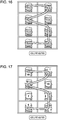
- Various embodiments displaying scan traces and showing the quantities of inventory items by the RFID reading terminal 100 are shown in Figs. 14-19 .
- the RFID reading terminal 100 can be further configured to receive from an external computer and to display a floor plan of the manufacturing, retail and/or storage facility.
- the RFID reading terminal can be further configured to display its position on the floor plan.
- the RFID reading terminal can be further configured to display in two or more different colors one or more areas containing the items which have already been scanned and one or more areas containing the items which have not yet been scanned.
- RFID reading device 333 can be compliant with EPC TM Class-1 Generation-2 UHF RFID Protocol for Communications at 860 MHz - 960 MHz by EPCglobal, commonly known as the "Gen 2" standard, which defines physical and logical requirements for a passive-backscatter, interrogator-talks-first (ITF) RFID system operating in the 860 MHz - 960 MHz frequency range.
- EPC TM Class-1 Generation-2 UHF RFID Protocol for Communications at 860 MHz - 960 MHz by EPCglobal commonly known as the "Gen 2" standard, which defines physical and logical requirements for a passive-backscatter, interrogator-talks-first (ITF) RFID system operating in the 860 MHz - 960 MHz frequency range.
- RFID reading terminal 100 can transmit information to a passive RFID tag by modulating an RF signal in the 860-960MHz frequency range.
- An RFID tag can receive both information and operating energy from the RF signal transmitted by the RFID reading terminal 100.
- RFID reading terminal 100 can receive information from the RFID tag by transmitting a continuous-wave (CW) RF signal to the RFID tag.
- Continuous wave can refer to any waveform transmitted by an RFID reading device and suitable to power a passive RFID tag, e.g., a sinusoid at a given frequency.
- the RFID tag can respond by modulating the reflection coefficient of its antenna, thus backscattering an information signal to the RFID reading terminal 100.
- the RFID tag can modulate the reflection coefficient of its antenna only responsive to receiving an RFID signal from RFID reading terminal 100.
- RFID reading terminal 100 can be configured to send information to one or more RFID tags by modulating an RF carrier using double-sideband amplitude shift keying (DSB-ASK), single-sideband amplitude shift keying (DSB-ASK), or phase-reversal amplitude shift-keying (PR-ASK) using a pulse-interval encoding (PIE) format.
- RFID tags can receive their operating energy from the same modulated RF carrier.
- the RFID reading terminal 100 can be configured to receive information from an RFID tag by transmitting an unmodulated RF carrier and listening for a backscatter reply.
- RFID tags can transmit information by backscatter-modulating the amplitude and/or phase of the RFID carrier.
- RFID tags can encode the backscattered data using, e.g ., FM0 baseband or Miller modulation of a subcarrier at the data rate.
- the encoding method to be employed by an RFID tag can be selected by the RFID reading terminal 100.
- RFID reading terminal can establish one or more sessions with one or more RFID tags.
- An RFID tag can support at least one session-dependent flag for every session.
- the session-dependent flag can have two states.
- An RFID tag can invert a session-dependent flag responsive to receiving a command from RFID reading terminal 100.
- Tag resources other than session-dependent flags can be shared among sessions.
- an RFID tag can support a selected status flag indicating that the tag was selected by the RFID reading terminal 100.
- an RFID tag Responsive to receiving an interrogation signal transmitted by the RFID reading terminal 100, an RFID tag can transmit a response signal back to RFID reading terminal 100.
- the response signal can contain useful data, e.g., an Electronic Product Code (EPC) identifier, or a tag identifier (TID).
- EPC Electronic Product Code
- TID tag identifier
- the response signal can include a representation of a binary string, at least part of which is equal to at least part one of the specified one or more target item identifiers.
- RFID reading terminal can implement EPC TM Class-1 Generation-2 UHF RFID Protocol for Communications at 860 MHz - 960 MHz by EPCglobal.
- the RFID reading terminal 100 can interrogate RFID tags using the commands described herein infra.
- Select command can be used by the RFID reading terminal 100 to select a particular RFID tag population for the subsequent inventory round. Select command can be applied successively to select a particular tag population based on user-specified criteria. Select command can include the following parameters:
- Inventory command set can be used by the RFID reading terminal 100 to single out one or more individual tags from a group.
- a tag can maintain up to four simultaneous sessions and a binary Inventoried flag for each session.
- Inventory command set includes the following commands:
- An RFID tag can implement a state machine. Once energized, a tag can change its current state to Ready. A selected tag can, responsive to receiving Query command, select a random integer from the range of [0; 2 Q-1 ]. If the value of zero is selected, the tag can transition to Reply state, backscattering a 16-bit random number. If a non-zero value is selected, the tag can load the selected random integer into its slot counter and change its state to Arbitrate.
- RFID reading terminal can acknowledge it with Ack command containing the same random number.
- the tag Responsive to receiving Ack command, the tag can change its state to Acknowledged and backscatter its protocol control (PC) bits, EPC and cyclic redundancy check (CRC) value.
- PC protocol control
- CRC cyclic redundancy check
- Unacknowledged tag can select a new random integer from the range of [0; 2 Q-1 ], load the value into its slot counter, and change its state to Arbitrate.
- QueryAdjust command Responsive to receiving QueryAdjust command, a tag in the Arbitrate state should decrement the value of its slot counter and backscatter its protocol control (PC) bits, EPC and CRC value if its slot counter is equal to zero.
- RFID reading terminal can send a QueryAdjust command causing the tag to invert its Inventoried flag and to transition to Ready state.
- Access command set can be used by the RFID reading terminal 100 for communicating with (reading from and writing to) a tag. An individual tag must be uniquely identified prior to access. Access command set includes the following commands:
- ReqRn command can be used by the RFID reading terminal 100 to request a handle from a tag; the handle can be used in the subsequent Access command set commands. Responsive to receiving Req_RN commands, a tag returns a 16-bit random integer (handle) and transitions from Acknowledged to Open or Secured state.
- Read command can be used by the RFID reading terminal 100 to read tag's Reserved, EPC, TID and User memory;
- Write command can be used by the RFID reading terminal 100 to write to tag's Reserved, EPC, TID and User memory;
- Kill command can be used by the RFID reading terminal 100 to permanently disable a tag
- Lock command can be used by the RFID reading terminal 100 to lock passwords preventing subsequent read or write operations; lock individual memory banks preventing subsequent write operations; permanently lock the lock status of passwords or memory banks;
- Access command can be used by the RFID reading terminal 100 to cause a tag having a non-zero access password to transition from Open to Secured state.
- the RFID reading terminal 100 can comprise a housing 52 within which other components of the RFID reading terminal 100 can be disposed.
- An LCD screen display with a touch screen sensor 554 can be disposed on the front panel 556.
- Also disposed on the front panel 556 can be a decode LED 558, a scan LED 559, and a keyboard 64 including a scan key 568 and navigation keys 72.
- An imaging window 74 can be disposed on the top panel of housing 52. Disposed on the side panel (best viewed in Fig.
- 21b can be an infra-red communication port 76, an access door to a secure digital (SD) memory interface 78, an audio jack 80, and a hand strap 82.
- Disposed on the bottom panel can be a multi-pin mechanical connector 84 and a hand strap clip 86.
- RFID reading device (not shown in Figs. 21a-21c ) can be disposed within the housing 52.
- a handheld RFID reader with integrated barcode scanner (either laser or imager barcode scanner), and a graphical display. No additional hardware modifications may be necessary.
- a software application executes on the RFID handheld device processor, to provide a user interface and control the barcode scanner.
- each retail fixture requires mounting of one or more custom decodable indicia (e.g., barcode) labels 2104 on the fixture 2101.
- decodable indicia e.g., barcode
- any decodable indicia can be employed.
- barcodes e.g., RFID tags, etc.
- custom barcode labels There may be at least two types of custom barcode labels: an initial point barcode label 2102 containing data to describe the physical characteristics of the fixture 2101, and multiple custom location barcode labels 2104 indicating locations or reference points on the fixture 2101.
- the output (e.g., laser) of the barcode scanner travels substantially in the same direction as the radiation pattern outputted by the RFID reader of the handheld device.
- the handheld device when the handheld device is pointed at the barcode label 2104, the handheld device also reads RFID tags located in an area proximate to the barcode label 2104. This allows the user to be guided along a path using the barcode labels 2104 in a particular order to force the handheld device to scan in a certain scan path 2106.
- FIG. 21 This is exemplified in Figure 21 .
- the user interface (not shown) prompts the user to barcode scan the custom location barcode labels 2104 in a particular order.
- the software application on the handheld device records the data and time of the barcode label 2104 at which the barcode label 2104 was scanned.
- the barcode labels 2104 are scanned in a particular order.
- the barcodes are scanned by the RFID reader first (after the reader is moved to S1,L location) from S1,L to S1,R and then from S1,R to S2, R and then from S2,R to S2,L and then from S2,L to S3,L and finally from S3,L to S3,R.
- scan path 2106 User feedback may be received indicating a successful barcode scan and the user may wait to receive feedback of successful scan before continuing RFID tag inventory (e.g., before scanning each successive barcode).
- the scan path 2106 assumes the handheld RFID reader is being conveyed in a substantially straight line therebetween, but this is not required (in one embodiment). Nonetheless, the scan path 2106 allows the RFID reader to scan directly over the correct path for minimizing read errors or missing RFID tags of items intended for inventorying.
- the data and time of the barcode label 2104 at which the barcode label 2104 was scanned is recorded by the handheld device and this data pair is entered into a table, with each row indicating a discrete point on the continuous scan path followed by the handheld RFID reader as the retail fixture is inventoried.
- An example of such table is illustrated in Figure 22B .
- there is a timestamp for each respective barcode label i.e., 00:05 for S1,L, 00:10 for S1,R, etc.). This method allows for verification of the rate at which the RFID reader is moved, as well as the scan path, and degree of RFID tag coverage achieved on the retail fixture.
- the handheld reader can estimate the scan path 2106 and display the same to the user to determine the path scanned, as well as indicate any missed areas.
- the system assumes the user moves the RFID reader 2100 at a predetermined rate (e.g., one foot/second). Using initial point fixture data, the time between scanning successive custom barcode labels is determined whether or not as reasonable. If so, then the system draws a line indicating scan path between the barcode labels 2104 on the display screen of the handheld device 2100.
- Figure 23A illustrates the locations of the barcode labels 2104 in accordance with one embodiment. As shown, at least some of the barcode labels 2104 should be placed along the path that the user wishes to scan for RFID tags. For example, the barcode labels 2104 should be on opposing ends of RFID tags that are intended to be scanned since the RFID handheld device should be moved between the two barcode labels 2104, which is also the location of RFID tags.
- each of the items shown on the fixture 2101 may have RFID tags even though the RFID tags are not explicitly visible in the Figures.
- the figures show jeans on the shelves of the fixture 2101 and each pair of jeans may have an RFID tag attached thereto and associated with such pair of jeans.
- the user determines that the jeans associated with the scanned RFID tag is present on the inventory.
- custom barcode label may be mounted at locations easily acquired with a barcode scanner, such as the edge of the shelf as shown in the Figures.
- the initial point barcode label 2102 may contain a physical, meta-description of the fixture, such as the shape of the fixture, the number of shelves of the fixture, physical dimensions of the fixture, etc.
- the initial point barcode label 2102 may be used during processing to validate motion between "points" (i.e. custom barcode labels).
- the initial point barcode label 2102 may also be used to verify what portion of fixture has been inventoried by handheld RFID reader.
- the scan path point table (e.g., the table in Figure 22B ) should contain data for all shelves or other areas of the fixture in the correct sequence. For example, in Figure 22A , S1,L to S2,L indicates shelf #1 was not inventoried, and S1.L to S1,R scanned below a predetermined threshold (e.g., one second) indicates a rate of motion of RFID reader that was too fast and inventory errors are likely since it is likely that interrogation signals were not able to allow the RFID to respond or the RFID reader was unable to read the response due to the movement.
- a predetermined threshold e.g., one second
Landscapes
- Engineering & Computer Science (AREA)
- Physics & Mathematics (AREA)
- General Physics & Mathematics (AREA)
- Theoretical Computer Science (AREA)
- Computer Vision & Pattern Recognition (AREA)
- Artificial Intelligence (AREA)
- Business, Economics & Management (AREA)
- Electromagnetism (AREA)
- Toxicology (AREA)
- Health & Medical Sciences (AREA)
- General Health & Medical Sciences (AREA)
- Economics (AREA)
- Marketing (AREA)
- Accounting & Taxation (AREA)
- General Business, Economics & Management (AREA)
- Tourism & Hospitality (AREA)
- Strategic Management (AREA)
- Quality & Reliability (AREA)
- Operations Research (AREA)
- Development Economics (AREA)
- Human Resources & Organizations (AREA)
- Entrepreneurship & Innovation (AREA)
- Finance (AREA)
Description
- Embodiments of the invention are generally related to encoded information reading (EIR) terminals and is specifically related to RFID reading terminals including radio-frequency identification (RFID) reading devices.
- RFID methods are widely used in a number of applications, including smart cards, item tracking in manufacturing, inventory management in retail, etc. An RFID tag can be attached, e.g., to an inventory item. An RFID reading terminal can be configured to read the memory of an RFID tag attached to an inventory item.
- Patent document number
US2014/0097247A describes an RFID reading terminal configured, responsive to receiving a user interface action, to capture an image of at least one part of a physical structure sustaining a plurality of inventory items, locate and decode optical decodable indicia into a message comprising an identifier of the physical structure. The RFID reading terminal can be further configured to retrieve from a database, using the identifier of the physical structure, a reference image and/or a description of the physical structure. The portable RFID reading terminal can be further configured, while being moved to follow an imaginary trajectory within the physical structure, to repetitively capture an image of the physical structure using the imaging device, determine orientation and the current spatial position of the RFID reading terminal relative to the physical structure responsive to identifying one or more objects within each captured image, and displaying the RFID scan trace. - Patent document number
US20130277430A1 discloses a method of mapping the location of at least one object in three dimensional space, relative to an initial point in three dimensional space by an EIR terminal which contains a microprocessor, memory, a scanning device, a motion sensing device, and a communication interface. The method includes scanning a signal of decodable indicia located at a pre-defined area of a physical object, locating the decodable indicia within this signal, decoding the decodable indicia into a decoded message. The decoded message is an identifier for said physical object, which is then displayed. After receiving an interface command, the EIR terminal is placed in mechanical contact with the pre-defined area of the physical object and a first spatial position is stored as a point of origin in the EIR terminal. - Additionally, in a retail sales environment, the use of handheld RFID reading devices to perform department inventory offers the potential benefits of performing such inventory operations more quickly than manual inventorying and hence at a lower cost, as well as improving the accuracy of inventory counts.
- However, there are drawbacks to this approach. Indeed, studies have shown these potential benefits of using RFID methods are only partially realized, mainly due to incomplete coverage of merchandise on fixtures in the retail department. As a result, inaccurate inventory counts are recorded using at least some RFID methods, leading to sub-optimal revenue (i.e. due to over- or under-stocking resulting from the inaccurate inventory counts).
- What is needed is a system and method for determining what portions of a given retail fixture have been properly inventoried using a handheld RFID reader. Such a system would ideally be easily integrated into existing handheld RFID reader products. As a result, the potential benefits of using handheld RFID reading devices for inventory operations will be realized to a much greater extent, increasing the revenue of the retail establishment.
- The present invention in its various aspects is as set out in the appended claims.
- For the purpose of illustrating the invention, the drawings show aspects of one or more embodiments of the invention. However, it should be understood that the present invention is not limited to the precise arrangements and instrumentalities shown in the drawings, wherein:
-
Fig. 1 schematically illustrates a scan trace displayed by an RFID reading terminal; -
Fig. 2 schematically illustrates an RF signal coverage shape by the RFID reading terminal; -
Fig. 3 schematically illustrates a component-level diagram of one embodiment of the RFID reading terminal; -
Fig. 4 schematically illustrates a network diagram of one embodiment of a data collection system employing RFID reading terminals; -
Figs. 5a-5b schematically illustrate determining a spatial position of the RF signal coverage shape based on the known position and orientation of an RF antenna relatively to the position of the field of view of a two-dimensional imager; -
Figs. 6-19 schematically illustrate various methods of displaying scan traces and selected inventory quantities by the RFID reading terminal; -
Figs. 20a-20c schematically illustrate embodiments of an RFID reading terminal. -
Fig. 21 illustrates a scan trace displayed by an RFID reading terminal using a point-based scan path determination in accordance with an embodiment. -
Fig. 22A illustrates a scan trace displayed by an RFID reading terminal using a point-based scan path determination in accordance with an embodiment. -
Fig. 22B illustrates a scan path point table used in conjunction withFig. 22A in accordance with an embodiment. -
Fig. 23A illustrates a scan trace displayed by an RFID reading terminal using a point-based scan path determination with positions of the decodable indicia similar to that ofFigure 22A in accordance with an embodiment. -
Fig. 23B illustrates a scan trace displayed by an RFID reading terminal using a point-based scan path determination with different positions of the decodable indicia in accordance with an embodiment. - The drawings are not necessarily to scale, emphasis instead generally being placed upon illustrating the principles of the invention. In the drawings, like numerals are used to indicate like parts throughout the various views.
- RFID reading devices usually offer improved efficiency over barcode scanning devices for retail inventory, by being capable of reading multiple RFID tags that are within range of the RF signal transmitted by an RFID reading device. A downside to this multiple-read capability is lack of scanned items localization, due to insufficient correlation between where the RFID reader is located or oriented, and the RFID tags being read. Retail inventory management typically requires more than 90% of the RFID tags present in a department to be successfully acquired during the inventory process. When this high accuracy is not achieved, it is necessary to rescan the entire department, since the locations of any unread RFID tags are unknown.
- In one embodiment, there is provided a portable radio-frequency identifier (RFID) reading terminal configured to present a visual indication of defined areas which have been scanned and areas which have not been scanned for RFID tags. Such a capability provides increased operational efficiency of RFID tag reading for retail inventory management. Various embodiments of the RFID reading terminal can be used in a numerous applications, including but not limited to, item tracking in manufacturing, storage, and retail, real-time inventory control systems, etc.
- Item tracking and/or inventory control can be implemented by placing an RFID tag on each inventory item. The RFID reading terminal can comprise at least one RFID reading device which can be configured to read and/or modify a memory of an RFID tag containing an encoded message. The RFID reading device can transmit and/or receive radio frequency (RF) signals to and from RFID tags attached to inventory items. Each RFID tag can store the tag identifier in its memory. An RFID tag attached to an inventory item can further store in the tag's memory a product code of the item, an EPC (Electronic Product Code) of the item, and/or at least one alphanumeric string identifying the item.
- The RFID reading device can be further configured to output decoded message data corresponding to the encoded message, e.g., decoded message data containing identifiers of the items to which the RFID tags are attached. The RFID reading terminal can be configured to store in its memory and/or transmit to an external computer the item identifiers received from the plurality of RFID tags.
- In a further aspect, the RFID reading terminal can be configured to receive an expected count of inventory items or an expected inventory list of items of interest stored within a storage, manufacturing, and/or retail facility. As used herein, "inventory list" shall refer to a collection of item descriptions, each item description comprising at least the item identifier.
- In one embodiment, the RFID reading terminal can receive the expected count of inventory items or the expected inventory list over a network from an external computer. In another embodiment, the RFID reading terminal can receive the expected count of inventory items or the expected inventory list via the user interface. In a yet another embodiment, the RFID reading terminal can receive the expected count of inventory items or the expected inventory list by reading an external memory device connected to one of the terminal's I/O ports (e.g., a USB port, or a PCMCIA interface). In a yet another embodiment, the RFID reading terminal can be equipped with a 2D imager and can receive the expected count of inventory items or the expected inventory list via the 2D imager, for example, by scanning a plurality of optical decodable indicia (e.g., a plurality of bar codes), or by acquiring an image of a textual document containing the expected count of inventory items or the expected inventory list and then processing the image using optical character recognition (OCR) methods.
- The RFID reading terminal can be further configured to reconcile the inventory of items stored within a storage, manufacturing, and/or retail facility against the expected count of inventory items or the expected inventory list by reading the RFID tags attached to the inventory items.
- The RFID reading terminal can read RFID tags from a range of distances and various terminal orientations with respect to an RFID tag being read. To further improve the reliability of scanning operations and the terminal's operator experience, the RFID reading terminal can be configured to emit audible signals (e.g., beeps) to indicate an occurrence of a pre-defined event, thus providing an audible feedback to the operator of the RFID reading terminal. In one embodiment, the RFID reading terminal can be configured to emit an audible signal of a first type every time a unique RFID tag has been successfully read and reconciled against an inventory list. The RFID reading terminal can be further configured to and emit an audible signal of a second type every time a unique RFID tag has been successfully read but failed to reconcile against the inventory list. The RFID reading terminal can be further configured to emit an audible signal of a third type every time a pre-defined timeout has elapsed without reading an RFID tag. However, the audible feedback inherently fails to indicate the location of the RFID tag having been successfully read.
- To further improve the readability of scanning operations, the RFID reading terminal can in one embodiment be configured to display on the terminal's display one or more scan traces, thus providing the terminal's operator with a visual feedback with respect to the scanning progress, as schematically shown in
Fig. 1 . - At any moment in time, the RF signal coverage emitted by an RFID reading terminal can be defined by a 3D shape, as schematically shown in
Fig. 2 . The form and size of the 3D shape defining the RF signal coverage can depend, among other factors, on the RFID transmit power level and the number and configuration of the RF antennas employed by the RFID reading device. In one embodiment, the 3D signal coverage shape can be provided by asphere 2020. In another embodiment, the 3D signal coverage shape can be provided by an ellipsoid. In a yet another embodiment, the 3D signal coverage shape can be provided by a cone. - At any given moment in time, a target scan area by an RFID reading terminal can be visualized as a
projection 2040 of the 3D RFsignal coverage shape 2020 onto an arbitrarily chosenplane 2050, including an imaginary plane. For a moving RFID reading terminal, a visual scan trace can be provided by a line defined by a multitude of time varying points, each point being aprojection 2040 of the 3D RFsignal coverage shape 2020 onto the arbitrarily chosenplane 2050 at a given moment in time. - In a further aspect, the imaginary plane onto which the visual scan trace is projected can be chosen to intersect a physical structure (e.g., a shelf) containing the inventory items, and thus the scan trace can be overlaid over an image of the physical structure as schematically shown in
Fig. 1 . - Component-level diagram of one embodiment of the RFID reading terminal is now being described with references to
Fig. 3 . TheRFID reading terminal 100 can comprise at least onemicroprocessor 310 and amemory 320, both coupled to thesystem bus 370. Themicroprocessor 310 can be provided by a general purpose microprocessor or by a specialized microprocessor (e.g., an ASIC). In one embodiment, RFID reading terminal 100 can comprise a single microprocessor which can be referred to as a central processing unit (CPU). In another embodiment, RFID reading terminal 100 can comprise two or more microprocessors, for example, a CPU providing some or most of the RFID reading terminal functionality and a specialized microprocessor performing some specific functionality. A skilled artisan would appreciate the fact that other schemes of processing tasks distribution among two or more microprocessors are within the scope of this disclosure. - RFID reading terminal 100 can further comprise a
communication interface 340 communicatively coupled to thesystem bus 370. In one embodiment, the communication interface can be provided by a wireless communication interface. The wireless communication interface can be configured to support, for example, but not limited to, the following protocols: at least one protocol of the IEEE 802.11/802.15/802.16 protocol family, at least one protocol of the HSPA/GSM/GPRS/EDGE protocol family, TDMA protocol, UMTS protocol, LTE protocol, and/or at least one protocol of the CDMA/1xEV-DO protocol family. - RFID reading terminal 100 can further comprise a
battery 356. In one embodiment, thebattery 356 can be provided by a replaceable rechargeable battery pack. TheRFID reading terminal 100 can further comprise aGPS receiver 380. TheRFID reading terminal 100 can further comprise at least oneconnector 390 configured to receive a subscriber identity module (SIM) card. - The
RFID reading terminal 100 can further comprise animaging device 330, provided, for example, by a two-dimensional imager. - The
RFID reading terminal 100 can further comprise anRFID reading device 333. In one embodiment, theRFID reading device 333 can be configured to read a memory of an RFID tag containing an encoded message and to output raw message data containing the encoded message. In another embodiment, theRFID reading device 333 can be configured to read a memory of an RFID tag containing an encoded message and to output decoded message data corresponding to the encoded message. As used herein, "message" is intended to denote a bit sequence or a character string comprising alphanumeric and/or non-alphanumeric characters. An encoded message can be used to convey information, such as identification of the source and the model of an item, for example, in an EPC code. - In one embodiment, the RFID reading terminal 100 can further comprise a graphical user interface including a
display adapter 175 and akeyboard 179. In one embodiment, the RFID reading terminal 100 can further comprise an audio output device, e.g., aspeaker 181. - It is not necessary that a device's primary function involve reading RFID tags in order to be considered an RFID reading terminal; for example, a cellular telephone, a smart phone, a PDA, or other portable computing device that is capable of reading RFID tags can be referred to as an RFID reading terminal for purposes of this disclosure.
- In a further aspect, the RFID reading terminal can be incorporated in a data collection system. One embodiment of the data collection system, schematically shown in
Fig. 4 , can include a plurality ofRFID reading terminals 100a-100z in communication with a plurality ofinterconnected networks 110a-110z. - An RFID reading terminal 100a-100z can establish a communication session with an
external computer 171. In one embodiment, network frames can be exchanged by theRFID reading terminal 100 and theexternal computer 171 via one ormore routers 140,access points 135, and other infrastructure elements. In another embodiment, theexternal computer 171 can be reachable by theRFID reading terminal 100 via a local area network (LAN). In a yet another embodiment, theexternal computer 171 can be reachable by theRFID reading terminal 100 via a wide area network (WAN). In a yet another embodiment, theexternal computer 171 can be reachable by the RFID reading terminal 100 directly (e.g., via a wired or wireless interface). A skilled artisan would appreciate the fact that other methods of providing interconnectivity between theRFID reading terminal 100 and theexternal computer 171 relying upon LANs, WANs, virtual private networks (VPNs), and/or other types of network are within the scope of this disclosure. - A "computer" herein shall refer to a programmable device for data processing and control, including a central processing unit (CPU), a memory, and at least one communication interface. For example, in one embodiment, a computer can be provided by a server running a single instance of a multi-tasking operating system. In another embodiment, a computer can be provided by a virtual server, i.e., an isolated instance of a guest operating system running within a host operating system. A "network" herein shall refer to a set of hardware and software components implementing a plurality of communication channels between two or more computers. A network can be provided, e.g., by a local area network (LAN), or a wide area network (WAN). While different networks can be designated herein, it is recognized that a single network as seen from the application layer interface to the network layer of the OSI model can comprise a plurality of lower layer networks, i.e., what can be regarded as a single Internet Protocol (IP) network, can include a plurality of different physical networks.
- The communications between the
RFID reading terminal 100 and theexternal computer 171 can comprise a series of requests and responses transmitted over one or more TCP connections. A skilled artisan would appreciate the fact that using various transport and application level protocols is within the scope and the spirit of the invention. - At least one of the messages transmitted by the RFID reading terminal 100 can include decoded message data corresponding to an RFID label attached to an inventory item. For example, an RFID reading terminal can transmit a request to the external computer to retrieve product information corresponding to a product identifier encoded by an RFID tag attached to a retail item, or to transmit an item tacking record for an item identified by an RFID tag attached to the item.
- As noted herein supra, the RFID reading terminal 100 can be configured to receive from the
external computer 171 an inventory list containing item identifiers, or count, of items stored within a storage, manufacturing, and/or retail facility. The inventory list or count can further contain storage location information of specific items. TheRFID reading terminal 100 can be further configured to reconcile an inventory of items stored in a manufacturing, retail and/or storage facility against the inventory list or count, by reading RFID tags attached to the items. TheRFID reading terminal 100 can be configured to transmit the reconciled list or count to theexternal computer 171. - The
RFID reading terminal 100 can be further configured to display a scan trace on the terminal's display, thus providing to the operator a visual feedback with respect to the scanning progress. In one embodiment, one or more scan traces 111a, 111b can be overlaid over an image ofphysical structure 115 containing the inventory items as schematically shown inFig. 1 . In a further aspect, for a moving RFID reading terminal, a visual scan trace can be provided by a line defined by a multitude of time varying points, each point being a projection of the 3D RF signal coverage shape onto a plane defined by thephysical structure 115 containing the inventory items at a given moment in time. - A noted herein supra, in one embodiment, the RFID reading terminal can comprise a two-dimensional imager. The RFID reading terminal can be configured to determine a spatial position of the RF signal coverage shape based on the known position and orientation of the RF antenna relatively to the position of the field of view (FOV) of the two-dimensional imager, as schematically shown in
Figs. 5a-5b . - The
plane 2050 can represent an arbitrary chosen plane, e.g., a plane intersecting a physical structure hosting one or more inventory items. The RF antenna can be oriented relatively to the view finder in such a way that thecentral axis 5010 of the field of view of the imager would be parallel to thecentral axis 5020 of the RF signal coverage shape by the antenna. Reducing the distance between the RFID reading terminal and theplane 2050 and/or increasing the RF transmit power level results in a larger projection of the RF signal coverage area onto theplane 5020, as schematically shown inFigs. 5a-5b . In the example ofFig. 5b , the lesser distance and/or the greater transmit power level results in a larger projection RF signal coverage area onto theplane 5020. The projection of the RF signal coverage shape onto theplane 2050 can be entirely within the FOV of the two-dimensional imager, as schematically shown inFig. 5a , or can be partially outside of the FOV of the two-dimensional imager, as schematically shown inFig. 5b . - In a further aspect, the RFID reading terminal can be configured to measure the distance to an object using a two-dimensional imager. Based on the known shape of the signal coverage and the distance and orientation of the RF antenna to a
physical structure 115 containing the inventory items, the RFID reading terminal can determine and display the projection of the 3D RF signal coverage shape onto the plane defined by thephysical structure 115. - In another embodiment, the RFID reading terminal can comprise one or more accelerometers and can be configured to determine the change of the spatial position and orientation of the RF signal coverage shape based on the proper acceleration values received from the accelerometers. In one illustrative embodiment, the RFID reading terminal can comprise three or more accelerometers.
- In one embodiment, the RFID reading terminal 100 can be further configured to display a quantity of scanned items, a quantity of items which have not been scanned yet, and/or a total quantity of items to be scanned, the latter quantity determined based on an inventory count or list of items describing a storage, manufacturing, and/or retail facility. A
progress indicator 191 ofFig. 1 shows the number of items scanned and the total number of items expected to be scanned. In another embodiment, the RFID reading terminal 100 can be further configured to display a both anabsolute progress bar 192a, and/or arelative progress bar 192b indicating a quantity of scanned items and a total quantity of items expected to be scanned, as shown inFig. 6 . - In one embodiment, the RFID reading terminal 100 can be further configured to display an
indicator 119 of the RF signal coverage over a scan trace, as schematically shown inFig. 7 . The indicator of the RF signal coverage can be determined as a line being a projection of the 3D RF signal coverage shape onto a plane defined by thephysical structure 115 containing the inventory items. In another embodiment, the RFID reading terminal 100 can be further configured to display anindicator 129 of the RF signal coverage over a current position aimed at by the RFID reading terminal, as schematically shown inFig. 8 . - In one embodiment, the RFID reading terminal 100 can be further configured to display a scan trace overlaid over an image of a physical structure (e.g., a shelf) containing one or more scanned items and one or more items to be scanned. In one embodiment, the image of the physical structure containing the inventory items can be received by the RFID reading terminal 100 over the network from an external computer. In another embodiment, the RFID reading terminal 100 can comprise a two-dimensional imager, and the image of the physical structure containing the inventory items can be acquired by the two-dimensional imager. In another embodiment, the image of the physical structure is drawn, with appropriate detail, on the RFID reading terminal display, based on a description of the physical structure received by the terminal 100 via the user interface, from an external peripheral device or from an external computer.
- In one embodiment, the items which have already been scanned and which have not yet been scanned can be displayed in two different colors, as schematically shown in
Fig. 9 . In another embodiment, the items which have already been scanned and which have not yet been scanned can be displayed using two different transparency patterns, as schematically shown inFigs. 10-11 . In one embodiment, a part of the physical structure (e.g., shelves or sections of shelves) containing inventory items having not been fully reconciled against the inventory list can be shown using a transparent pattern. In another embodiment, schematically shown inFig. 12 , multiple colors and/or transparency pattern can be used to display parts of physical structure containing the inventory items which have been fully reconciled, partially reconciled, or containing no items having been reconciled. In a yet another embodiment, schematically shown inFig. 13 , quantities of reconciled items can be displayed associated with groups of inventory items. Various embodiments displaying scan traces and showing the quantities of inventory items by theRFID reading terminal 100 are shown inFigs. 14-19 . - In one embodiment, schematically shown in
Fig. 20 , the RFID reading terminal 100 can be further configured to receive from an external computer and to display a floor plan of the manufacturing, retail and/or storage facility. The RFID reading terminal can be further configured to display its position on the floor plan. The RFID reading terminal can be further configured to display in two or more different colors one or more areas containing the items which have already been scanned and one or more areas containing the items which have not yet been scanned. - In a further aspect,
RFID reading device 333 can be compliant with EPC™ Class-1 Generation-2 UHF RFID Protocol for Communications at 860 MHz - 960 MHz by EPCglobal, commonly known as the "Gen 2" standard, which defines physical and logical requirements for a passive-backscatter, interrogator-talks-first (ITF) RFID system operating in the 860 MHz - 960 MHz frequency range. - In one embodiment, RFID reading terminal 100 can transmit information to a passive RFID tag by modulating an RF signal in the 860-960MHz frequency range. An RFID tag can receive both information and operating energy from the RF signal transmitted by the
RFID reading terminal 100. RFID reading terminal 100 can receive information from the RFID tag by transmitting a continuous-wave (CW) RF signal to the RFID tag. "Continuous wave" can refer to any waveform transmitted by an RFID reading device and suitable to power a passive RFID tag, e.g., a sinusoid at a given frequency. The RFID tag can respond by modulating the reflection coefficient of its antenna, thus backscattering an information signal to theRFID reading terminal 100. In one embodiment, the RFID tag can modulate the reflection coefficient of its antenna only responsive to receiving an RFID signal fromRFID reading terminal 100. - In a further aspect, RFID reading terminal 100 can be configured to send information to one or more RFID tags by modulating an RF carrier using double-sideband amplitude shift keying (DSB-ASK), single-sideband amplitude shift keying (DSB-ASK), or phase-reversal amplitude shift-keying (PR-ASK) using a pulse-interval encoding (PIE) format. RFID tags can receive their operating energy from the same modulated RF carrier.
- The
RFID reading terminal 100 can be configured to receive information from an RFID tag by transmitting an unmodulated RF carrier and listening for a backscatter reply. RFID tags can transmit information by backscatter-modulating the amplitude and/or phase of the RFID carrier. RFID tags can encode the backscattered data using, e.g., FM0 baseband or Miller modulation of a subcarrier at the data rate. The encoding method to be employed by an RFID tag can be selected by theRFID reading terminal 100. - In another aspect, RFID reading terminal can establish one or more sessions with one or more RFID tags. An RFID tag can support at least one session-dependent flag for every session. The session-dependent flag can have two states. An RFID tag can invert a session-dependent flag responsive to receiving a command from
RFID reading terminal 100. Tag resources other than session-dependent flags can be shared among sessions. In another aspect, an RFID tag can support a selected status flag indicating that the tag was selected by theRFID reading terminal 100. - Responsive to receiving an interrogation signal transmitted by the
RFID reading terminal 100, an RFID tag can transmit a response signal back toRFID reading terminal 100. The response signal can contain useful data, e.g., an Electronic Product Code (EPC) identifier, or a tag identifier (TID). The response signal can include a representation of a binary string, at least part of which is equal to at least part one of the specified one or more target item identifiers. - In one embodiment, RFID reading terminal can implement EPC™ Class-1 Generation-2 UHF RFID Protocol for Communications at 860 MHz - 960 MHz by EPCglobal. The
RFID reading terminal 100 can interrogate RFID tags using the commands described herein infra. - Select command can be used by the RFID reading terminal 100 to select a particular RFID tag population for the subsequent inventory round. Select command can be applied successively to select a particular tag population based on user-specified criteria. Select command can include the following parameters:
- Target parameter indicates whether Select command modifies a tag's SL flag or Inventoried flag, and in the latter case it further specifies one of four available sessions (S0,.., S3);
- Action parameter indicates whether matching tags assert or deassert SL flag, or set their Inventoried flag to A or B state; tags conforming to the contents of MemBank, Pointer, Length, and Mask parameters are considered to be matching;
- Mask parameter contains a bit string that a tag should compare to a memory location specified by MemBank, Pointer, and Length parameters;
- MemBank parameter specifies the memory bank to which Mask parameter refers (EPC, TID, or User);
- Pointer parameter specifies a memory start location for Mask;
- Length parameter specifies the number of bits of memory for Mask; if Length is equal to zero, all tags are considered matching.
- Inventory command set can be used by the RFID reading terminal 100 to single out one or more individual tags from a group. A tag can maintain up to four simultaneous sessions and a binary Inventoried flag for each session. Inventory command set includes the following commands:
- Query command can be used to initiate and specify an inventory round; it contains a slot counter value (Q=0 to 15) determining the number of slots in the round; the command also includes Sel parameter specifying which tags should respond to the Query.
- QueryAdjust command can be used to adjust the value of the tag's slot counter Q without changing any other parameters;
- QueryRep command can be used to repeat the last Query command;
- Ack command can be used to acknowledge a tag's response;
- NAK command can be used to force a tag to change its state to Arbitrate.
- An RFID tag can implement a state machine. Once energized, a tag can change its current state to Ready. A selected tag can, responsive to receiving Query command, select a random integer from the range of [0; 2Q-1]. If the value of zero is selected, the tag can transition to Reply state, backscattering a 16-bit random number. If a non-zero value is selected, the tag can load the selected random integer into its slot counter and change its state to Arbitrate.
- Responsive to receiving the tag transmission, RFID reading terminal can acknowledge it with Ack command containing the same random number. Responsive to receiving Ack command, the tag can change its state to Acknowledged and backscatter its protocol control (PC) bits, EPC and cyclic redundancy check (CRC) value. Unacknowledged tag can select a new random integer from the range of [0; 2Q-1], load the value into its slot counter, and change its state to Arbitrate. Responsive to receiving QueryAdjust command, a tag in the Arbitrate state should decrement the value of its slot counter and backscatter its protocol control (PC) bits, EPC and CRC value if its slot counter is equal to zero.
- Responsive to receiving the tag's transmission of its PC, EPC and 16-bit CRC value, RFID reading terminal can send a QueryAdjust command causing the tag to invert its Inventoried flag and to transition to Ready state.
- Access command set can be used by the
RFID reading terminal 100 for communicating with (reading from and writing to) a tag. An individual tag must be uniquely identified prior to access. Access command set includes the following commands: - ReqRn command can be used by the RFID reading terminal 100 to request a handle from a tag; the handle can be used in the subsequent Access command set commands. Responsive to receiving Req_RN commands, a tag returns a 16-bit random integer (handle) and transitions from Acknowledged to Open or Secured state.
- Read command can be used by the RFID reading terminal 100 to read tag's Reserved, EPC, TID and User memory;
- Write command can be used by the RFID reading terminal 100 to write to tag's Reserved, EPC, TID and User memory;
- Kill command can be used by the RFID reading terminal 100 to permanently disable a tag;
- Lock command can be used by the RFID reading terminal 100 to lock passwords preventing subsequent read or write operations; lock individual memory banks preventing subsequent write operations; permanently lock the lock status of passwords or memory banks;
- Access command can be used by the RFID reading terminal 100 to cause a tag having a non-zero access password to transition from Open to Secured state.
- A skilled artisan would appreciate the fact that other methods of interrogating RFID tags by the
RFID reading terminal 100 are within the scope of this disclosure. - One embodiment of the
RFID reading terminal 100 is schematically shown inFigs. 21a (front panel view), 21b (side panel view), and 21c (bottom panel view). TheRFID reading terminal 100 can comprise ahousing 52 within which other components of the RFID reading terminal 100 can be disposed. An LCD screen display with atouch screen sensor 554 can be disposed on thefront panel 556. Also disposed on thefront panel 556 can be adecode LED 558, ascan LED 559, and akeyboard 64 including ascan key 568 andnavigation keys 72. Animaging window 74 can be disposed on the top panel ofhousing 52. Disposed on the side panel (best viewed inFig. 21b ) can be an infra-red communication port 76, an access door to a secure digital (SD)memory interface 78, anaudio jack 80, and ahand strap 82. Disposed on the bottom panel (best viewed inFig. 22c ) can be a multi-pinmechanical connector 84 and ahand strap clip 86. RFID reading device (not shown inFigs. 21a-21c ) can be disposed within thehousing 52. - Other embodiments of the present application use a handheld RFID reader with integrated barcode scanner (either laser or imager barcode scanner), and a graphical display. No additional hardware modifications may be necessary. A software application executes on the RFID handheld device processor, to provide a user interface and control the barcode scanner.
- To use this system, each retail fixture requires mounting of one or more custom decodable indicia (e.g., barcode) labels 2104 on the
fixture 2101. It should be noted that any decodable indicia can be employed. However, for ease of explanation and illustration, the below embodiments are described using barcodes. It should be understood that decodable indicia other than barcodes could be used (e.g., RFID tags, etc.). - There may be at least two types of custom barcode labels: an initial
point barcode label 2102 containing data to describe the physical characteristics of thefixture 2101, and multiple customlocation barcode labels 2104 indicating locations or reference points on thefixture 2101. - Additionally, it is noted that the output (e.g., laser) of the barcode scanner travels substantially in the same direction as the radiation pattern outputted by the RFID reader of the handheld device. In this regard, when the handheld device is pointed at the
barcode label 2104, the handheld device also reads RFID tags located in an area proximate to thebarcode label 2104. This allows the user to be guided along a path using thebarcode labels 2104 in a particular order to force the handheld device to scan in acertain scan path 2106. - This is exemplified in
Figure 21 . As a user moves thehandheld RFID reader 2100 while inventorying the fixture 2101 (e.g., the user points the radiation pattern of thehandheld RFID reader 2100 toward a first point of the fixture 2101), the user interface (not shown) prompts the user to barcode scan the customlocation barcode labels 2104 in a particular order. As each such location barcode label is scanned in the defined order, the software application on the handheld device records the data and time of thebarcode label 2104 at which thebarcode label 2104 was scanned. - As mentioned above, the
barcode labels 2104 are scanned in a particular order. For example, inFigure 22A , the barcodes are scanned by the RFID reader first (after the reader is moved to S1,L location) from S1,L to S1,R and then from S1,R to S2, R and then from S2,R to S2,L and then from S2,L to S3,L and finally from S3,L to S3,R. This is illustrated byscan path 2106. User feedback may be received indicating a successful barcode scan and the user may wait to receive feedback of successful scan before continuing RFID tag inventory (e.g., before scanning each successive barcode). Thescan path 2106 assumes the handheld RFID reader is being conveyed in a substantially straight line therebetween, but this is not required (in one embodiment). Nonetheless, thescan path 2106 allows the RFID reader to scan directly over the correct path for minimizing read errors or missing RFID tags of items intended for inventorying. - As mentioned above, the data and time of the
barcode label 2104 at which thebarcode label 2104 was scanned is recorded by the handheld device and this data pair is entered into a table, with each row indicating a discrete point on the continuous scan path followed by the handheld RFID reader as the retail fixture is inventoried. An example of such table is illustrated inFigure 22B . As shown, there is a timestamp for each respective barcode label (i.e., 00:05 for S1,L, 00:10 for S1,R, etc.). This method allows for verification of the rate at which the RFID reader is moved, as well as the scan path, and degree of RFID tag coverage achieved on the retail fixture. - In this regard, the handheld reader can estimate the
scan path 2106 and display the same to the user to determine the path scanned, as well as indicate any missed areas. To do this, the system assumes the user moves theRFID reader 2100 at a predetermined rate (e.g., one foot/second). Using initial point fixture data, the time between scanning successive custom barcode labels is determined whether or not as reasonable. If so, then the system draws a line indicating scan path between the barcode labels 2104 on the display screen of thehandheld device 2100. -
Figure 23A illustrates the locations of thebarcode labels 2104 in accordance with one embodiment. As shown, at least some of thebarcode labels 2104 should be placed along the path that the user wishes to scan for RFID tags. For example, thebarcode labels 2104 should be on opposing ends of RFID tags that are intended to be scanned since the RFID handheld device should be moved between the twobarcode labels 2104, which is also the location of RFID tags. - It should be noted that each of the items shown on the
fixture 2101 may have RFID tags even though the RFID tags are not explicitly visible in the Figures. For example, the figures show jeans on the shelves of thefixture 2101 and each pair of jeans may have an RFID tag attached thereto and associated with such pair of jeans. Thus, when each respective RFID tag is scanned and the data from the RFID tag is determined, the user determines that the jeans associated with the scanned RFID tag is present on the inventory. - It is noted that the custom barcode label may be mounted at locations easily acquired with a barcode scanner, such as the edge of the shelf as shown in the Figures. Information encoded in each barcode must match mounting location in accordance with some embodiments. For example, if the barcode data = "S1,L" or "Shelf 1, left side", then barcode should be mounted at the left side of the first shelf. Mislocated barcode labels may degrade the accuracy of depicted scan path of handheld RFID reader since the system is preprogrammed with particular locations of the barcode labels.
- It should be also noted that the initial
point barcode label 2102 may contain a physical, meta-description of the fixture, such as the shape of the fixture, the number of shelves of the fixture, physical dimensions of the fixture, etc. The initialpoint barcode label 2102 may be used during processing to validate motion between "points" (i.e. custom barcode labels). - The initial
point barcode label 2102 may also be used to verify what portion of fixture has been inventoried by handheld RFID reader. The scan path point table (e.g., the table inFigure 22B ) should contain data for all shelves or other areas of the fixture in the correct sequence. For example, inFigure 22A , S1,L to S2,L indicates shelf #1 was not inventoried, and S1.L to S1,R scanned below a predetermined threshold (e.g., one second) indicates a rate of motion of RFID reader that was too fast and inventory errors are likely since it is likely that interrogation signals were not able to allow the RFID to respond or the RFID reader was unable to read the response due to the movement.
Claims (20)
- An RFID reader (2100), comprising:an antenna adapted to read RFID tags attached to items on an object (2101);a barcode reader integrated with the RFID reader (2100),the barcode reader being adapted to project a light to read barcodes (2104) mounted at known locations on the object (2101);characterized in that:
the RFID reader (2100) is adapted to:retrieve the known locations of the barcodes (2104) on the object from a memory;estimate a scan path (2106) for the object (2101) based on the known locations of the barcodes (2104) on the object, the scan path (2106) being a suggested travel path of the RFID reader (2100) to collect information about the items on the object (2101) and including points on the scan path where the barcode reader reads the barcodes (2104) and the antenna reads RFID tags attached to the items;prompt, via a user interface, a user to scan barcodes (2104) in a particular order forcing the handheld device to scan in the scan path,wherein the scan path (2106) assumes the RFID reader is being conveyed in a substantially straight line between barcodes (2104);record the time at which the barcode (2014) was scanned and the data of the barcode label. - The RFID reader (2100) of claim 1, wherein a radiation pattern of the RFID reader (2100) projects in the direction of the projected light of the barcode reader.
- The RFID reader (2100) of claim 1, wherein the RFID reader (2100) is configured, by reading the RFID tags attached to the items, to reconcile an inventory of the items on the object against at least one of: an expected inventory list and an expected count of items; and
the RFID reader (2100) is configured to receive from an external computer (171) at least one of: the expected inventory list and the expected count of items. - The RFID reader (2100) of claim 1, further comprising a user interface;
wherein the RFID reader (2100) is configured, by reading the RFID tags attached to the items, to reconcile an inventory of items on the object against at least one of: an expected inventory list and an expected count of items; and
the RFID reader (2100) is configured to receive via the user interface at least one of: the expected inventory list and the expected count of items. - The RFID reader (2100) of claim 1, further comprising a two-dimensional imager;
wherein the RFID reader (2100) is configured, by reading the RFID tags attached to the items, to reconcile an inventory of items on the object against at least one of: an expected inventory list and an expected count of items; and
the RFID reader (2100) is configured to receive via the two-dimensional imager at least one of: the expected inventory list and the expected count of items. - The RFID reader (2100) of claim 1, wherein the RFID reader (2100) is configured, by reading the RFID tags attached to the items, to reconcile an inventory of items on the object against at least one of: an expected inventory list and an expected count of items; and
the RFID reader (2100) is configured to receive from an external memory device at least one of: the expected inventory list and the expected count of items. - The RFID reader (2100) of claim 3, wherein
the RFID reader (2100) is further configured to transmit to a second external computer at least one of: a list of read RFID tags and a count of read RFID tags. - The RFID reader (2100) of claim 3, wherein
the RFID reader (2100) is further configured to transmit to the external computer (171) at least one of: a list of read RFID tags and a count of read RFID tags. - The RFID reader (2100) of claim 1, further comprising a two-dimensional imager;
wherein the RFID reader (2100) is further configured to determine a spatial position of an RF signal coverage shape (2020) based on a known position and orientation of the RF antenna relatively to a position of a field of view of the two-dimensional imager. - The RFID reader (2100) of claim 1, further comprising a two-dimensional imager;
wherein the RFID reader (2100) is further configured to measure a distance to the object (2101) using the two-dimensional imager; and
the RFID reader (2100) is further configured to determine and display a projection (2040) of an RF signal coverage shape (2020) onto a plane (2050) defined by the object (2101). - The RFID reader (2100) of claim 1, further comprising at least one accelerometer;
wherein the RFID reader (2100) is further configured to determine a change of a spatial position and orientation of an RF signal coverage shape (2020) based on-acceleration values received from the at least one accelerometer. - The RFID reader (2100) of claim 1, wherein the RFID reader (2100) is further configured to display at least one of: a quantity of scanned items, a quantity of items which have not been scanned yet, and a total quantity of items to be scanned.
- The RFID reader (2100) of claim 1, wherein the RFID reader (2100) is further configured to display an indicator of a ratio of quantity of scanned items to a total quantity of items to be scanned.
- The RFID reader (2100) of claim 1, wherein the RFID reader (2100) is further configured to display the scan path (2106) overlaid over an image of the object (2101).
- The RFID reader (2100) of claim 14, wherein the RFID reader (2100) is further configured to: receive an image of the object (2101).
- The RFID reader (2100) of claim 14, wherein the RFID reader (2100) is further configured to:receive a description of the object (2101);create an image of the object (2101) based on the description.
- The RFID reader (2100) of claim 14, further comprising a two-dimensional imager;
wherein the RFID reader (2100) is further configured, using the two-dimensional imager, to acquire an image of the object (2101). - The RFID reader (2100) of claim 14, wherein the RFID reader (2100) is further configured to display an indicator (119) of an RF signal coverage over the scan path (2106) overlaid over an image of the object (2101).
- The RFID reader (2100) of claim 1, wherein the RFID reader (2100) is further configured to display an indicator (119) of an RF signal coverage over a current position within the scan path (2106).
- A method of reading RFID tags, comprising:reading RFID tags attached to items on an object (2101) using an RFID reader (2100) reading barcodes (2104) mounted at known locations on the object (2101) using a barcode reader that is integrated with the RFID reader (2100);characterized by the following steps:retrieving said known locations of the barcodes on the object from a memory;estimating, using the RFID reader (2100), a scan path (2106) for the object (2101) based on the known locations of the barcodes (2104) on the object, the scan path (2106) being a suggested travel path of the RFID reader (2100) to collect information about the items on the object (2101);prompting, via a user interface, a user to scan barcodes (2104) in a particular order forcing the handheld device to scan in the scan path,wherein the scan path (2106) assumes the RFID reader is being conveyed in a substantially straight line between barcodes (2104); andrecording the time at which the barcode label (2014) was scanned and the data of the barcode label.
Applications Claiming Priority (1)
| Application Number | Priority Date | Filing Date | Title |
|---|---|---|---|
| US201462098748P | 2014-12-31 | 2014-12-31 |
Publications (2)
| Publication Number | Publication Date |
|---|---|
| EP3040904A1 EP3040904A1 (en) | 2016-07-06 |
| EP3040904B1 true EP3040904B1 (en) | 2021-04-21 |
Family
ID=55066399
Family Applications (1)
| Application Number | Title | Priority Date | Filing Date |
|---|---|---|---|
| EP15202688.6A Active EP3040904B1 (en) | 2014-12-31 | 2015-12-24 | Portable rfid reading terminal with visual indication of scan trace |
Country Status (2)
| Country | Link |
|---|---|
| US (1) | US9619683B2 (en) |
| EP (1) | EP3040904B1 (en) |
Families Citing this family (16)
| Publication number | Priority date | Publication date | Assignee | Title |
|---|---|---|---|---|
| US9872135B2 (en) * | 2014-12-31 | 2018-01-16 | Intermec Ip Corp. | Systems and methods for displaying location information for RFID tags |
| USD771631S1 (en) * | 2015-06-02 | 2016-11-15 | Hand Held Products, Inc. | Mobile computer housing |
| CN105184454A (en) * | 2015-08-19 | 2015-12-23 | 北京京东方多媒体科技有限公司 | Article management system and article management method |
| US20170228688A1 (en) * | 2016-02-10 | 2017-08-10 | Tri-8, Inc. | System and method for strategic rfid tag reading using physically dispersed barcodes and supplemental automated inventory management through mobile rfid readers |
| JP2018028852A (en) * | 2016-08-19 | 2018-02-22 | 東芝テック株式会社 | Reader and program |
| US10679179B2 (en) * | 2017-04-21 | 2020-06-09 | Sensormatic Electronics, LLC | Systems and methods for an improved tag counting process |
| USD883286S1 (en) * | 2018-02-06 | 2020-05-05 | Symbol Technologies, Llc | Data capture device |
| CA3097860A1 (en) * | 2018-04-20 | 2019-10-24 | Real Time Intel, Llc | Rfid based sequencing system and method |
| US10628723B2 (en) | 2018-07-10 | 2020-04-21 | Datamax-O'neil Corporation | Methods, systems, and apparatuses for encoding a radio frequency identification (RFID) inlay |
| US10740580B2 (en) * | 2018-09-28 | 2020-08-11 | Datalogic Ip Tech S.R.L. | Multi-function sound chamber for handheld barcode reader |
| CA3119986A1 (en) * | 2018-11-15 | 2020-05-22 | Metrc Llc | Method and apparatus for tracking one or more plants and/or plant based products and/or tracking the sale of products derived from the same, utilizing rfid technology |
| US10732380B2 (en) * | 2018-12-21 | 2020-08-04 | Zebra Technologies Corporation | Swipe scanning for variable focus imaging systems |
| JP7360847B2 (en) * | 2019-08-27 | 2023-10-13 | 東芝テック株式会社 | information processing equipment |
| USD955390S1 (en) * | 2019-11-11 | 2022-06-21 | Intermec Ip Corporation | RFID handheld scanner |
| WO2022179340A1 (en) * | 2021-02-27 | 2022-09-01 | 华为技术有限公司 | Data transmission method and device thereof |
| CA3151898A1 (en) * | 2021-03-31 | 2022-09-30 | Walmart Apollo, Llc | On-hand inventory accuracy system |
Family Cites Families (108)
| Publication number | Priority date | Publication date | Assignee | Title |
|---|---|---|---|---|
| US5664231A (en) | 1994-04-29 | 1997-09-02 | Tps Electronics | PCMCIA interface card for coupling input devices such as barcode scanning engines to personal digital assistants and palmtop computers |
| US6543691B1 (en) | 1995-01-03 | 2003-04-08 | Jerome H. Lemelson | Method and apparatus for encoding and decoding bar codes with primary and secondary information and method of using such bar codes |
| US5729001A (en) | 1996-01-11 | 1998-03-17 | Webscan, Inc. | Method for evaluating a succession of bar code symbols |
| BR9913043B1 (en) | 1998-08-14 | 2012-10-02 | processes for ordering a group of cluttered items having radio frequency identification elements, for using a hand held radio frequency identification device to read information from a radio frequency identification element, and for using a radio frequency identification device for identifying and locating items having a radio frequency identification element. | |
| JP4237868B2 (en) | 1999-05-10 | 2009-03-11 | 株式会社トプコン | Image forming system |
| US6318636B1 (en) * | 1999-09-21 | 2001-11-20 | Intermec Ip Corp. | Method and apparatus to read different types of data carriers, such RFID tags and machine-readable symbols, and a user interface for the same |
| HK1050581A1 (en) | 2000-01-14 | 2003-06-27 | 3M Innovative Properties Company | User interface for portable rfid reader |
| US20070124216A1 (en) | 2000-03-07 | 2007-05-31 | Michael Lucas | Systems and methods for locating and purchasing proximal inventory items |
| US7085400B1 (en) | 2000-06-14 | 2006-08-01 | Surgical Navigation Technologies, Inc. | System and method for image based sensor calibration |
| JP4059620B2 (en) | 2000-09-20 | 2008-03-12 | 株式会社リコー | Coordinate detection method, coordinate input / detection device, and storage medium |
| US6857567B2 (en) | 2000-10-17 | 2005-02-22 | Psc Scanning, Inc. | System and method for training and monitoring data reader operators |
| US7464877B2 (en) | 2003-11-13 | 2008-12-16 | Metrologic Instruments, Inc. | Digital imaging-based bar code symbol reading system employing image cropping pattern generator and automatic cropped image processor |
| US7708205B2 (en) | 2003-11-13 | 2010-05-04 | Metrologic Instruments, Inc. | Digital image capture and processing system employing multi-layer software-based system architecture permitting modification and/or extension of system features and functions by way of third party code plug-ins |
| US6659344B2 (en) | 2000-12-06 | 2003-12-09 | Ncr Corporation | Automated monitoring of activity of shoppers in a market |
| US7407196B2 (en) | 2003-08-06 | 2008-08-05 | Swagelok Company | Tube fitting with separable tube gripping device |
| US7076441B2 (en) | 2001-05-03 | 2006-07-11 | International Business Machines Corporation | Identification and tracking of persons using RFID-tagged items in store environments |
| US7003138B2 (en) | 2001-10-05 | 2006-02-21 | Honeywell International Inc. | System and method for geographically referencing an improvement image |
| US7603518B2 (en) | 2005-12-19 | 2009-10-13 | Commvault Systems, Inc. | System and method for improved media identification in a storage device |
| US7756319B2 (en) | 2002-02-13 | 2010-07-13 | Ascension Technology Corporation | Optical system for determining the angular position of a radiating point source and method of employing |
| US7063256B2 (en) | 2003-03-04 | 2006-06-20 | United Parcel Service Of America | Item tracking and processing systems and methods |
| EP1616289A4 (en) | 2003-04-07 | 2008-04-02 | Silverbrook Res Pty Ltd | Sensing device for coded data |
| US20050131645A1 (en) | 2003-06-09 | 2005-06-16 | Panopoulos Peter J. | Machine having automatic transport with scanning and GPS functions |
| US7308158B2 (en) | 2003-06-20 | 2007-12-11 | Eastman Kodak Company | Imaging method and system |
| US7199719B2 (en) | 2004-03-24 | 2007-04-03 | Dan Alan Steinberg | RFID tag reader with tag location indicated by visible light beam |
| US8659619B2 (en) | 2004-03-26 | 2014-02-25 | Intellectual Ventures Fund 83 Llc | Display device and method for determining an area of importance in an original image |
| US20060017545A1 (en) | 2004-03-26 | 2006-01-26 | Volpi John P | Radio frequency identification interrogation systems and methods of operating the same |
| US7951003B2 (en) | 2004-06-14 | 2011-05-31 | Igt | Wireless identification and tracking in gaming systems |
| US7320221B2 (en) | 2004-08-04 | 2008-01-22 | Oramt Technologies Inc. | Method and apparatus for using geothermal energy for the production of power |
| US7263205B2 (en) | 2004-12-06 | 2007-08-28 | Dspv, Ltd. | System and method of generic symbol recognition and user authentication using a communication device with imaging capabilities |
| US7583178B2 (en) | 2005-03-16 | 2009-09-01 | Datalogic Mobile, Inc. | System and method for RFID reader operation |
| US7237721B2 (en) | 2005-05-24 | 2007-07-03 | Nokia Corporation | Image processing for pattern detection |
| US7405662B2 (en) | 2005-06-14 | 2008-07-29 | Datalogic Mobile, Inc. | Wireless tag ranging |
| JP2006350806A (en) | 2005-06-17 | 2006-12-28 | Toshiba Tec Corp | Wireless tag recognition device and product sales data processing device |
| US7323992B2 (en) | 2005-06-21 | 2008-01-29 | International Business Machines Corporation | Method and system for aggregation of RFID signal sources and composite to develop a unique signature |
| US7696874B2 (en) | 2005-11-08 | 2010-04-13 | Casella Waste Systems, Inc. | Methods and systems for monitoring groups of items, elements, and/or products using radio frequency identification |
| US7602288B2 (en) | 2005-12-01 | 2009-10-13 | Frito-Lay North America, Inc. | Method for slap-and-ship RFID labeling |
| US20110284625A1 (en) | 2005-12-16 | 2011-11-24 | Taylor Smith | Digital image capture and processing system supporting multiple third party code plug-ins with configuration files having conditional programming logic controlling the chaining of multiple third-party plug-ins |
| US7427846B2 (en) | 2006-02-02 | 2008-09-23 | International Business Machines Corporation | Method of optimizing servo controller power in two-dimensional flexure mems storage devices |
| US7857219B2 (en) | 2006-05-26 | 2010-12-28 | Symbol Technologies, Inc. | Imaging reader target object finder system |
| US7627191B2 (en) | 2006-08-14 | 2009-12-01 | Xerox Corporation | Image manipulation |
| US7786865B2 (en) | 2006-08-23 | 2010-08-31 | Psion Teklogix Inc. | RFID reader and range indicating method for the RFID reader |
| US7821400B2 (en) | 2006-09-29 | 2010-10-26 | Datalogic Scanning, Inc. | System and method for verifying number of wireless tagged items in a transaction |
| EP2088778B1 (en) | 2006-10-04 | 2013-12-18 | Nikon Corporation | Electronic apparatus and electronic camera |
| US7855643B2 (en) | 2006-11-10 | 2010-12-21 | Round Rock Research, Llc | Tracking systems, passive RFIDs, methods of locating and identifying RFIDs, and methods of tracking items |
| US20080111661A1 (en) | 2006-11-15 | 2008-05-15 | Symbol Technologies, Inc. | Method and system for transmission power reduction in RFID interrogators |
| US20080122785A1 (en) | 2006-11-25 | 2008-05-29 | John Paul Harmon | Portable display with improved functionality |
| US8149094B2 (en) | 2006-12-06 | 2012-04-03 | Hewlett-Packard Development Company, L.P. | Clustering methods for radio-frequency-identifier networks |
| US7833013B2 (en) | 2006-12-13 | 2010-11-16 | Diers Nelson R | Device, method and kit for determining orthodontic dimensions |
| US7775431B2 (en) | 2007-01-17 | 2010-08-17 | Metrologic Instruments, Inc. | Method of and apparatus for shipping, tracking and delivering a shipment of packages employing the capture of shipping document images and recognition-processing thereof initiated from the point of shipment pickup and completed while the shipment is being transported to its first scanning point to facilitate early customs clearance processing and shorten the delivery time of packages to point of destination |
| JP5118858B2 (en) | 2007-02-06 | 2013-01-16 | 株式会社ユニバーサルエンターテインメント | Control device, wireless IC tag reading system, and wireless IC tag reading device |
| US8083422B1 (en) | 2007-03-02 | 2011-12-27 | Marvell International Ltd. | Handheld tattoo printer |
| US7965186B2 (en) | 2007-03-09 | 2011-06-21 | Corning Cable Systems, Llc | Passive RFID elements having visual indicators |
| KR100875924B1 (en) | 2007-03-14 | 2008-12-26 | 한국전자통신연구원 | RDF tag power management device and method |
| US20080249899A1 (en) | 2007-04-05 | 2008-10-09 | Nasser Gabriel G | System and Method for Inventory |
| WO2008129875A1 (en) | 2007-04-13 | 2008-10-30 | Panasonic Corporation | Detector, detection method, and integrated circuit for detection |
| US8179238B2 (en) | 2007-07-23 | 2012-05-15 | R&L Carriers, Inc. | Information transmission and processing systems and methods for freight carriers |
| JP5020738B2 (en) | 2007-08-10 | 2012-09-05 | キヤノン株式会社 | Image reading apparatus, control method thereof, and control program |
| US8624710B2 (en) | 2007-08-16 | 2014-01-07 | Farpointe Data, Inc. | System and method for interrogation radio-frequency identification |
| US7743991B2 (en) | 2007-11-14 | 2010-06-29 | Hand Held Products, Inc. | Automatic image transmission of difficult to read symbols |
| US8251280B2 (en) | 2007-12-10 | 2012-08-28 | Glory Ltd. | Bar-code ticket processing apparatus, method of controlling bar-code ticket processing apparatus, and bar-code ticket processing system |
| WO2009075019A1 (en) | 2007-12-10 | 2009-06-18 | Glory Ltd. | Bar-code ticket processing device and its control method |
| US7961908B2 (en) | 2007-12-21 | 2011-06-14 | Zoran Corporation | Detecting objects in an image being acquired by a digital camera or other electronic image acquisition device |
| JP4984164B2 (en) | 2008-01-30 | 2012-07-25 | ブラザー工業株式会社 | Wireless tag information reader |
| US8718133B2 (en) | 2008-03-26 | 2014-05-06 | Samsung Electronics Co., Ltd. | Method and system for image scaling detection |
| US20090243801A1 (en) | 2008-03-31 | 2009-10-01 | Martin Strzelczyk | Method and System for Utilizing an RFID Sensor Tag as RF Power Measurement Embedded in Antenna |
| US8334775B2 (en) | 2008-05-23 | 2012-12-18 | Guardian Technologies | RFID-based asset security and tracking system, apparatus and method |
| US8520979B2 (en) | 2008-08-19 | 2013-08-27 | Digimarc Corporation | Methods and systems for content processing |
| US8805110B2 (en) | 2008-08-19 | 2014-08-12 | Digimarc Corporation | Methods and systems for content processing |
| US8421627B2 (en) | 2008-08-21 | 2013-04-16 | Symbol Technologies, Inc. | Method for associating and RFID tag with a known region |
| US8446254B2 (en) | 2008-11-03 | 2013-05-21 | Thingmagic, Inc. | Methods and apparatuses for RFID tag range determination |
| JP4733198B2 (en) | 2008-11-17 | 2011-07-27 | 東芝テック株式会社 | Information registration apparatus and program |
| US8581722B2 (en) | 2008-12-04 | 2013-11-12 | Element Id, Inc. | Apparatus, system, and method for automated item tracking |
| US8139867B2 (en) | 2008-12-05 | 2012-03-20 | Tandent Vision Science, Inc. | Image segregation system architecture |
| US8463079B2 (en) | 2008-12-16 | 2013-06-11 | Intermec Ip Corp. | Method and apparatus for geometrical measurement using an optical device such as a barcode and/or RFID scanner |
| US8456306B2 (en) | 2008-12-17 | 2013-06-04 | Symbol Technologies, Inc. | Association based locationing for RFID |
| US20100201520A1 (en) | 2009-02-12 | 2010-08-12 | Symbol Technologies, Inc. | System for determining item location based on feedback from fixed radio frequency identification (rfid) readers and/or fixed rfid beacon tags |
| US8258953B2 (en) | 2009-02-12 | 2012-09-04 | Symbol Technologies, Inc. | Displaying radio frequency identification (RFID) read range of an RFID reader based on feedback from fixed RFID beacon tags |
| JP5316124B2 (en) | 2009-03-13 | 2013-10-16 | 日産自動車株式会社 | Laser welding equipment |
| WO2010120358A2 (en) | 2009-04-13 | 2010-10-21 | Nintendo Co., Ltd. | In-store wireless shopping network using hand-held devices |
| AU2010239209A1 (en) | 2009-04-22 | 2011-12-15 | Franwell, Inc. | A wearable RFID system |
| US7786925B1 (en) | 2009-05-13 | 2010-08-31 | Lockheed Martin Corporation | Determination of the outline of an elevated object |
| US8478029B2 (en) | 2009-05-26 | 2013-07-02 | Tandent Vision Science, Inc. | Multi-resolution analysis in image segregation |
| US9148202B2 (en) | 2009-06-03 | 2015-09-29 | Disney Enterprises, Inc. | RFID-based communication devices and methods for location-based entertainment systems |
| US8768313B2 (en) | 2009-08-17 | 2014-07-01 | Digimarc Corporation | Methods and systems for image or audio recognition processing |
| CN102165516A (en) | 2009-08-31 | 2011-08-24 | 松下电器产业株式会社 | Image display control device, image display control method and integrated circuit |
| US8786440B2 (en) | 2009-10-02 | 2014-07-22 | Checkpoint Systems, Inc. | Calibration of beamforming nodes in a configurable monitoring device system |
| US20120200537A1 (en) | 2009-10-19 | 2012-08-09 | Akihiro Okano | Coordinate position detection device, method of detecting coordinate position, and display device |
| KR20110055244A (en) | 2009-11-19 | 2011-05-25 | 삼성전자주식회사 | Recording medium storing digital photographing device and method thereof and program for executing same |
| JP2011114633A (en) | 2009-11-27 | 2011-06-09 | Fujitsu Ltd | Antenna device and system including the same |
| US8188908B2 (en) | 2010-01-29 | 2012-05-29 | Amtech Systems, LLC | System and method for measurement of distance to a tag by a modulated backscatter RFID reader |
| US8672222B2 (en) * | 2010-05-03 | 2014-03-18 | Avery Dennison Corporation | Infrastructure-mounted RFID tags |
| US9461872B2 (en) | 2010-06-02 | 2016-10-04 | Hewlett Packard Enterprise Development Lp | Compressing data in a wireless network |
| US8439260B2 (en) | 2010-10-18 | 2013-05-14 | Jiazheng Shi | Real-time barcode recognition using general cameras |
| TWI433040B (en) | 2010-12-28 | 2014-04-01 | Claridy Solutions Inc | Application of radio frequency identification technology in intelligent lockers and management methods |
| US9507976B2 (en) | 2011-08-22 | 2016-11-29 | Metrologic Instruments, Inc. | Encoded information reading terminal with item locate functionality |
| WO2013090603A1 (en) | 2011-12-16 | 2013-06-20 | Cozad Thomas Michael Jr | Systems and methods for managing product location information |
| US20130154809A1 (en) | 2011-12-19 | 2013-06-20 | Symbol Technologies, Inc. | Method and apparatus for locating an item within a radio frequency identification monitored area |
| US9041518B2 (en) * | 2012-01-26 | 2015-05-26 | Hand Held Products, Inc. | Portable RFID reading terminal with visual indication of scan trace |
| US8727225B2 (en) | 2012-04-20 | 2014-05-20 | Honeywell International Inc. | System and method for calibration and mapping of real-time location data |
| US9443119B2 (en) | 2012-04-20 | 2016-09-13 | Hand Held Products, Inc. | Portable encoded information reading terminal configured to locate groups of RFID tags |
| US9013275B2 (en) | 2012-04-20 | 2015-04-21 | Hand Held Products, Inc. | Portable encoded information reading terminal configured to adjust transmit power level |
| US8881982B2 (en) | 2012-04-20 | 2014-11-11 | Honeywell Scanning & Mobility | Portable encoded information reading terminal configured to acquire images |
| US9064254B2 (en) | 2012-05-17 | 2015-06-23 | Honeywell International Inc. | Cloud-based system for reading of decodable indicia |
| US9092683B2 (en) | 2012-07-10 | 2015-07-28 | Honeywell International Inc. | Cloud-based system for processing of decodable indicia |
| US10387484B2 (en) * | 2012-07-24 | 2019-08-20 | Symbol Technologies, Llc | Mobile device for displaying a topographical area defined by a barcode |
| US9081994B2 (en) * | 2012-10-05 | 2015-07-14 | Hand Held Products, Inc. | Portable RFID reading terminal with visual indication of scan trace |
| US20140104416A1 (en) | 2012-10-16 | 2014-04-17 | Hand Held Products, Inc. | Dimensioning system |
| US9292719B2 (en) | 2014-07-31 | 2016-03-22 | Hand Held Products, Inc. | RFID apparatus calibration |
-
2015
- 2015-12-24 EP EP15202688.6A patent/EP3040904B1/en active Active
- 2015-12-29 US US14/982,839 patent/US9619683B2/en active Active
Non-Patent Citations (1)
| Title |
|---|
| None * |
Also Published As
| Publication number | Publication date |
|---|---|
| US20160188930A1 (en) | 2016-06-30 |
| US9619683B2 (en) | 2017-04-11 |
| EP3040904A1 (en) | 2016-07-06 |
Similar Documents
| Publication | Publication Date | Title |
|---|---|---|
| EP3040904B1 (en) | Portable rfid reading terminal with visual indication of scan trace | |
| US9652736B2 (en) | Portable RFID reading terminal with visual indication of scan trace | |
| US10387692B2 (en) | Portable encoded information reading terminal configured to locate groups of RFID tags | |
| US9607184B2 (en) | Portable RFID reading terminal with visual indication of scan trace | |
| US10248817B2 (en) | Reading RFID tags in defined spatial locations | |
| US10127414B2 (en) | Portable encoded information reading terminal configured to adjust transmit power level | |
| US10049238B2 (en) | Encoded information reading terminal with item locate functionality | |
| US9477861B2 (en) | Encoded information reading terminal including multiple encoded information reading devices | |
| GB2512687A (en) | Reading RFID tags in defined spatial locations |
Legal Events
| Date | Code | Title | Description |
|---|---|---|---|
| PUAI | Public reference made under article 153(3) epc to a published international application that has entered the european phase |
Free format text: ORIGINAL CODE: 0009012 |
|
| 17P | Request for examination filed |
Effective date: 20151224 |
|
| AK | Designated contracting states |
Kind code of ref document: A1 Designated state(s): AL AT BE BG CH CY CZ DE DK EE ES FI FR GB GR HR HU IE IS IT LI LT LU LV MC MK MT NL NO PL PT RO RS SE SI SK SM TR |
|
| AX | Request for extension of the european patent |
Extension state: BA ME |
|
| STAA | Information on the status of an ep patent application or granted ep patent |
Free format text: STATUS: EXAMINATION IS IN PROGRESS |
|
| 17Q | First examination report despatched |
Effective date: 20170407 |
|
| GRAP | Despatch of communication of intention to grant a patent |
Free format text: ORIGINAL CODE: EPIDOSNIGR1 |
|
| STAA | Information on the status of an ep patent application or granted ep patent |
Free format text: STATUS: GRANT OF PATENT IS INTENDED |
|
| INTG | Intention to grant announced |
Effective date: 20201119 |
|
| GRAS | Grant fee paid |
Free format text: ORIGINAL CODE: EPIDOSNIGR3 |
|
| GRAA | (expected) grant |
Free format text: ORIGINAL CODE: 0009210 |
|
| STAA | Information on the status of an ep patent application or granted ep patent |
Free format text: STATUS: THE PATENT HAS BEEN GRANTED |
|
| AK | Designated contracting states |
Kind code of ref document: B1 Designated state(s): AL AT BE BG CH CY CZ DE DK EE ES FI FR GB GR HR HU IE IS IT LI LT LU LV MC MK MT NL NO PL PT RO RS SE SI SK SM TR |
|
| REG | Reference to a national code |
Ref country code: GB Ref legal event code: FG4D |
|
| REG | Reference to a national code |
Ref country code: CH Ref legal event code: EP |
|
| REG | Reference to a national code |
Ref country code: DE Ref legal event code: R096 Ref document number: 602015068310 Country of ref document: DE |
|
| REG | Reference to a national code |
Ref country code: IE Ref legal event code: FG4D |
|
| REG | Reference to a national code |
Ref country code: AT Ref legal event code: REF Ref document number: 1385409 Country of ref document: AT Kind code of ref document: T Effective date: 20210515 |
|
| REG | Reference to a national code |
Ref country code: NL Ref legal event code: FP |
|
| REG | Reference to a national code |
Ref country code: LT Ref legal event code: MG9D |
|
| REG | Reference to a national code |
Ref country code: AT Ref legal event code: MK05 Ref document number: 1385409 Country of ref document: AT Kind code of ref document: T Effective date: 20210421 |
|
| PG25 | Lapsed in a contracting state [announced via postgrant information from national office to epo] |
Ref country code: FI Free format text: LAPSE BECAUSE OF FAILURE TO SUBMIT A TRANSLATION OF THE DESCRIPTION OR TO PAY THE FEE WITHIN THE PRESCRIBED TIME-LIMIT Effective date: 20210421 Ref country code: LT Free format text: LAPSE BECAUSE OF FAILURE TO SUBMIT A TRANSLATION OF THE DESCRIPTION OR TO PAY THE FEE WITHIN THE PRESCRIBED TIME-LIMIT Effective date: 20210421 Ref country code: AT Free format text: LAPSE BECAUSE OF FAILURE TO SUBMIT A TRANSLATION OF THE DESCRIPTION OR TO PAY THE FEE WITHIN THE PRESCRIBED TIME-LIMIT Effective date: 20210421 Ref country code: BG Free format text: LAPSE BECAUSE OF FAILURE TO SUBMIT A TRANSLATION OF THE DESCRIPTION OR TO PAY THE FEE WITHIN THE PRESCRIBED TIME-LIMIT Effective date: 20210721 Ref country code: HR Free format text: LAPSE BECAUSE OF FAILURE TO SUBMIT A TRANSLATION OF THE DESCRIPTION OR TO PAY THE FEE WITHIN THE PRESCRIBED TIME-LIMIT Effective date: 20210421 |
|
| PG25 | Lapsed in a contracting state [announced via postgrant information from national office to epo] |
Ref country code: LV Free format text: LAPSE BECAUSE OF FAILURE TO SUBMIT A TRANSLATION OF THE DESCRIPTION OR TO PAY THE FEE WITHIN THE PRESCRIBED TIME-LIMIT Effective date: 20210421 Ref country code: GR Free format text: LAPSE BECAUSE OF FAILURE TO SUBMIT A TRANSLATION OF THE DESCRIPTION OR TO PAY THE FEE WITHIN THE PRESCRIBED TIME-LIMIT Effective date: 20210722 Ref country code: IS Free format text: LAPSE BECAUSE OF FAILURE TO SUBMIT A TRANSLATION OF THE DESCRIPTION OR TO PAY THE FEE WITHIN THE PRESCRIBED TIME-LIMIT Effective date: 20210821 Ref country code: RS Free format text: LAPSE BECAUSE OF FAILURE TO SUBMIT A TRANSLATION OF THE DESCRIPTION OR TO PAY THE FEE WITHIN THE PRESCRIBED TIME-LIMIT Effective date: 20210421 Ref country code: SE Free format text: LAPSE BECAUSE OF FAILURE TO SUBMIT A TRANSLATION OF THE DESCRIPTION OR TO PAY THE FEE WITHIN THE PRESCRIBED TIME-LIMIT Effective date: 20210421 Ref country code: PL Free format text: LAPSE BECAUSE OF FAILURE TO SUBMIT A TRANSLATION OF THE DESCRIPTION OR TO PAY THE FEE WITHIN THE PRESCRIBED TIME-LIMIT Effective date: 20210421 Ref country code: PT Free format text: LAPSE BECAUSE OF FAILURE TO SUBMIT A TRANSLATION OF THE DESCRIPTION OR TO PAY THE FEE WITHIN THE PRESCRIBED TIME-LIMIT Effective date: 20210823 Ref country code: NO Free format text: LAPSE BECAUSE OF FAILURE TO SUBMIT A TRANSLATION OF THE DESCRIPTION OR TO PAY THE FEE WITHIN THE PRESCRIBED TIME-LIMIT Effective date: 20210721 Ref country code: ES Free format text: LAPSE BECAUSE OF FAILURE TO SUBMIT A TRANSLATION OF THE DESCRIPTION OR TO PAY THE FEE WITHIN THE PRESCRIBED TIME-LIMIT Effective date: 20210421 |
|
| REG | Reference to a national code |
Ref country code: DE Ref legal event code: R097 Ref document number: 602015068310 Country of ref document: DE |
|
| PG25 | Lapsed in a contracting state [announced via postgrant information from national office to epo] |
Ref country code: RO Free format text: LAPSE BECAUSE OF FAILURE TO SUBMIT A TRANSLATION OF THE DESCRIPTION OR TO PAY THE FEE WITHIN THE PRESCRIBED TIME-LIMIT Effective date: 20210421 Ref country code: SK Free format text: LAPSE BECAUSE OF FAILURE TO SUBMIT A TRANSLATION OF THE DESCRIPTION OR TO PAY THE FEE WITHIN THE PRESCRIBED TIME-LIMIT Effective date: 20210421 Ref country code: SM Free format text: LAPSE BECAUSE OF FAILURE TO SUBMIT A TRANSLATION OF THE DESCRIPTION OR TO PAY THE FEE WITHIN THE PRESCRIBED TIME-LIMIT Effective date: 20210421 Ref country code: EE Free format text: LAPSE BECAUSE OF FAILURE TO SUBMIT A TRANSLATION OF THE DESCRIPTION OR TO PAY THE FEE WITHIN THE PRESCRIBED TIME-LIMIT Effective date: 20210421 Ref country code: DK Free format text: LAPSE BECAUSE OF FAILURE TO SUBMIT A TRANSLATION OF THE DESCRIPTION OR TO PAY THE FEE WITHIN THE PRESCRIBED TIME-LIMIT Effective date: 20210421 Ref country code: CZ Free format text: LAPSE BECAUSE OF FAILURE TO SUBMIT A TRANSLATION OF THE DESCRIPTION OR TO PAY THE FEE WITHIN THE PRESCRIBED TIME-LIMIT Effective date: 20210421 |
|
| PLBE | No opposition filed within time limit |
Free format text: ORIGINAL CODE: 0009261 |
|
| STAA | Information on the status of an ep patent application or granted ep patent |
Free format text: STATUS: NO OPPOSITION FILED WITHIN TIME LIMIT |
|
| 26N | No opposition filed |
Effective date: 20220124 |
|
| PG25 | Lapsed in a contracting state [announced via postgrant information from national office to epo] |
Ref country code: IS Free format text: LAPSE BECAUSE OF FAILURE TO SUBMIT A TRANSLATION OF THE DESCRIPTION OR TO PAY THE FEE WITHIN THE PRESCRIBED TIME-LIMIT Effective date: 20210821 Ref country code: AL Free format text: LAPSE BECAUSE OF FAILURE TO SUBMIT A TRANSLATION OF THE DESCRIPTION OR TO PAY THE FEE WITHIN THE PRESCRIBED TIME-LIMIT Effective date: 20210421 |
|
| PG25 | Lapsed in a contracting state [announced via postgrant information from national office to epo] |
Ref country code: MC Free format text: LAPSE BECAUSE OF FAILURE TO SUBMIT A TRANSLATION OF THE DESCRIPTION OR TO PAY THE FEE WITHIN THE PRESCRIBED TIME-LIMIT Effective date: 20210421 Ref country code: IT Free format text: LAPSE BECAUSE OF FAILURE TO SUBMIT A TRANSLATION OF THE DESCRIPTION OR TO PAY THE FEE WITHIN THE PRESCRIBED TIME-LIMIT Effective date: 20210421 |
|
| REG | Reference to a national code |
Ref country code: CH Ref legal event code: PL |
|
| PG25 | Lapsed in a contracting state [announced via postgrant information from national office to epo] |
Ref country code: LU Free format text: LAPSE BECAUSE OF NON-PAYMENT OF DUE FEES Effective date: 20211224 Ref country code: IE Free format text: LAPSE BECAUSE OF NON-PAYMENT OF DUE FEES Effective date: 20211224 |
|
| PG25 | Lapsed in a contracting state [announced via postgrant information from national office to epo] |
Ref country code: LI Free format text: LAPSE BECAUSE OF NON-PAYMENT OF DUE FEES Effective date: 20211231 Ref country code: CH Free format text: LAPSE BECAUSE OF NON-PAYMENT OF DUE FEES Effective date: 20211231 |
|
| PG25 | Lapsed in a contracting state [announced via postgrant information from national office to epo] |
Ref country code: HU Free format text: LAPSE BECAUSE OF FAILURE TO SUBMIT A TRANSLATION OF THE DESCRIPTION OR TO PAY THE FEE WITHIN THE PRESCRIBED TIME-LIMIT; INVALID AB INITIO Effective date: 20151224 |
|
| PG25 | Lapsed in a contracting state [announced via postgrant information from national office to epo] |
Ref country code: CY Free format text: LAPSE BECAUSE OF FAILURE TO SUBMIT A TRANSLATION OF THE DESCRIPTION OR TO PAY THE FEE WITHIN THE PRESCRIBED TIME-LIMIT Effective date: 20210421 |
|
| PG25 | Lapsed in a contracting state [announced via postgrant information from national office to epo] |
Ref country code: MK Free format text: LAPSE BECAUSE OF FAILURE TO SUBMIT A TRANSLATION OF THE DESCRIPTION OR TO PAY THE FEE WITHIN THE PRESCRIBED TIME-LIMIT Effective date: 20210421 |
|
| PG25 | Lapsed in a contracting state [announced via postgrant information from national office to epo] |
Ref country code: TR Free format text: LAPSE BECAUSE OF FAILURE TO SUBMIT A TRANSLATION OF THE DESCRIPTION OR TO PAY THE FEE WITHIN THE PRESCRIBED TIME-LIMIT Effective date: 20210421 |
|
| PG25 | Lapsed in a contracting state [announced via postgrant information from national office to epo] |
Ref country code: MT Free format text: LAPSE BECAUSE OF FAILURE TO SUBMIT A TRANSLATION OF THE DESCRIPTION OR TO PAY THE FEE WITHIN THE PRESCRIBED TIME-LIMIT Effective date: 20210421 |
|
| PGFP | Annual fee paid to national office [announced via postgrant information from national office to epo] |
Ref country code: BE Payment date: 20241224 Year of fee payment: 10 Ref country code: NL Payment date: 20241224 Year of fee payment: 10 |
|
| PGFP | Annual fee paid to national office [announced via postgrant information from national office to epo] |
Ref country code: GB Payment date: 20241217 Year of fee payment: 10 |
|
| PGFP | Annual fee paid to national office [announced via postgrant information from national office to epo] |
Ref country code: FR Payment date: 20241227 Year of fee payment: 10 |
|
| PGFP | Annual fee paid to national office [announced via postgrant information from national office to epo] |
Ref country code: DE Payment date: 20241227 Year of fee payment: 10 |