EP1408001B1 - Industrial vehicle equipped with material handling work controller - Google Patents
Industrial vehicle equipped with material handling work controller Download PDFInfo
- Publication number
- EP1408001B1 EP1408001B1 EP02712415.5A EP02712415A EP1408001B1 EP 1408001 B1 EP1408001 B1 EP 1408001B1 EP 02712415 A EP02712415 A EP 02712415A EP 1408001 B1 EP1408001 B1 EP 1408001B1
- Authority
- EP
- European Patent Office
- Prior art keywords
- load
- forks
- mark
- image
- camera
- Prior art date
- Legal status (The legal status is an assumption and is not a legal conclusion. Google has not performed a legal analysis and makes no representation as to the accuracy of the status listed.)
- Expired - Lifetime
Links
- 230000008021 deposition Effects 0.000 claims description 161
- 238000001514 detection method Methods 0.000 claims description 57
- 238000004364 calculation method Methods 0.000 claims description 12
- 230000000007 visual effect Effects 0.000 claims description 6
- 238000012790 confirmation Methods 0.000 claims description 3
- 238000000034 method Methods 0.000 description 128
- 230000008569 process Effects 0.000 description 97
- 238000012545 processing Methods 0.000 description 75
- 239000013598 vector Substances 0.000 description 64
- 238000010586 diagram Methods 0.000 description 48
- 230000004913 activation Effects 0.000 description 31
- 230000008901 benefit Effects 0.000 description 19
- 230000002194 synthesizing effect Effects 0.000 description 19
- 230000000994 depressogenic effect Effects 0.000 description 16
- 230000000694 effects Effects 0.000 description 12
- 238000003780 insertion Methods 0.000 description 12
- 230000037431 insertion Effects 0.000 description 12
- 230000008859 change Effects 0.000 description 11
- 238000013461 design Methods 0.000 description 10
- 238000013459 approach Methods 0.000 description 6
- 230000000881 depressing effect Effects 0.000 description 6
- 230000006870 function Effects 0.000 description 6
- 210000003813 thumb Anatomy 0.000 description 6
- 230000009471 action Effects 0.000 description 5
- 210000003811 finger Anatomy 0.000 description 5
- 239000013589 supplement Substances 0.000 description 5
- 230000001133 acceleration Effects 0.000 description 4
- 239000012530 fluid Substances 0.000 description 4
- 238000006243 chemical reaction Methods 0.000 description 3
- 239000000470 constituent Substances 0.000 description 3
- 230000006872 improvement Effects 0.000 description 3
- 238000012544 monitoring process Methods 0.000 description 3
- 230000035945 sensitivity Effects 0.000 description 3
- 230000008685 targeting Effects 0.000 description 3
- 230000001174 ascending effect Effects 0.000 description 2
- 239000003086 colorant Substances 0.000 description 2
- 238000004891 communication Methods 0.000 description 2
- 239000004973 liquid crystal related substance Substances 0.000 description 2
- 230000000717 retained effect Effects 0.000 description 2
- 230000000903 blocking effect Effects 0.000 description 1
- 238000012937 correction Methods 0.000 description 1
- 230000001934 delay Effects 0.000 description 1
- 210000000887 face Anatomy 0.000 description 1
- 210000003128 head Anatomy 0.000 description 1
- 238000005259 measurement Methods 0.000 description 1
- 230000007935 neutral effect Effects 0.000 description 1
- 238000003909 pattern recognition Methods 0.000 description 1
- 230000002250 progressing effect Effects 0.000 description 1
- 239000013049 sediment Substances 0.000 description 1
Images


Classifications
-
- B—PERFORMING OPERATIONS; TRANSPORTING
- B66—HOISTING; LIFTING; HAULING
- B66F—HOISTING, LIFTING, HAULING OR PUSHING, NOT OTHERWISE PROVIDED FOR, e.g. DEVICES WHICH APPLY A LIFTING OR PUSHING FORCE DIRECTLY TO THE SURFACE OF A LOAD
- B66F9/00—Devices for lifting or lowering bulky or heavy goods for loading or unloading purposes
- B66F9/06—Devices for lifting or lowering bulky or heavy goods for loading or unloading purposes movable, with their loads, on wheels or the like, e.g. fork-lift trucks
- B66F9/075—Constructional features or details
- B66F9/0755—Position control; Position detectors
-
- G—PHYSICS
- G05—CONTROLLING; REGULATING
- G05D—SYSTEMS FOR CONTROLLING OR REGULATING NON-ELECTRIC VARIABLES
- G05D1/00—Control of position, course, altitude or attitude of land, water, air or space vehicles, e.g. using automatic pilots
- G05D1/20—Control system inputs
- G05D1/24—Arrangements for determining position or orientation
- G05D1/244—Arrangements for determining position or orientation using passive navigation aids external to the vehicle, e.g. markers, reflectors or magnetic means
-
- G—PHYSICS
- G05—CONTROLLING; REGULATING
- G05D—SYSTEMS FOR CONTROLLING OR REGULATING NON-ELECTRIC VARIABLES
- G05D1/00—Control of position, course, altitude or attitude of land, water, air or space vehicles, e.g. using automatic pilots
- G05D1/60—Intended control result
- G05D1/656—Interaction with payloads or external entities
- G05D1/667—Delivering or retrieving payloads
-
- G—PHYSICS
- G05—CONTROLLING; REGULATING
- G05D—SYSTEMS FOR CONTROLLING OR REGULATING NON-ELECTRIC VARIABLES
- G05D2105/00—Specific applications of the controlled vehicles
- G05D2105/20—Specific applications of the controlled vehicles for transportation
- G05D2105/28—Specific applications of the controlled vehicles for transportation of freight
-
- G—PHYSICS
- G05—CONTROLLING; REGULATING
- G05D—SYSTEMS FOR CONTROLLING OR REGULATING NON-ELECTRIC VARIABLES
- G05D2107/00—Specific environments of the controlled vehicles
- G05D2107/70—Industrial sites, e.g. warehouses or factories
-
- G—PHYSICS
- G05—CONTROLLING; REGULATING
- G05D—SYSTEMS FOR CONTROLLING OR REGULATING NON-ELECTRIC VARIABLES
- G05D2109/00—Types of controlled vehicles
- G05D2109/10—Land vehicles
-
- G—PHYSICS
- G05—CONTROLLING; REGULATING
- G05D—SYSTEMS FOR CONTROLLING OR REGULATING NON-ELECTRIC VARIABLES
- G05D2111/00—Details of signals used for control of position, course, altitude or attitude of land, water, air or space vehicles
- G05D2111/10—Optical signals
Definitions
- the present invention relates to a load handling operation aiding apparatus in an industrial vehicle.
- the invention relates to an industrial vehicle equipped with a load handling operation aiding apparatus which assists a positioning work to position a load carrying apparatus, such as a pallet, for example, by allowing a picked-up image of a work area of the load carrying apparatus, provided on an industrial vehicle, to be seen through the screen of display means provided in a driver's seat or the like.
- this type of industrial vehicle for example, a forklift
- a forklift has a multi-level mast provided on its vehicle body, and a carriage having a load carrying apparatus (attachment), such as forks; is so provided as to be liftable along a mast.
- a load carrying apparatus attachment
- a driver operates a load handling lever (lift lever) to protract or retract the multi-level mast by hydraulic driving to move the forks upward along the mast to position the load carrying apparatus to a pallet in the rack or a shelf surface.
- the driver must manipulate the load handling lever while checking with the eyes if the forks are positioned to holes in the pallet or a position above the shelf surface by looking up at a high place (e.g., 3 to 6 meters) from below. It is however difficult to determine if the forks and a pallet or the like are positioned with the eyes by looking up at a high place, and even a skilled person needs time for this positioning, disadvantageously.
- a high place e.g. 3 to 6 meters
- U.S. Patent No. 5586620 discloses an apparatus that assists a positioning work of the forks at a high place by attaching a camera to the carriage, picking up the state of a rack, a pallet or the like positioned in front of the forks and allowing the driver in the driver's seat to see the picked-up image via the screen of a display device.
- This apparatus can allow an image picked up by the camera to be seen via the screen of the display device.
- the present invention has been devised to overcome the problems and aims at providing a load handling operation aiding apparatus in an industrial vehicle, which can reliably assist the positioning of a load carrying apparatus through a screen.
- a load handling operation aiding apparatus in an industrial vehicle, which is provided with a load carrying apparatus in a movable manner.
- the load carrying apparatus is positioned to a load handling target according to its movement.
- the load handling operation aiding apparatus has display means and detection means for detecting a position of the load handling target.
- Display control means displays positioning information for supporting positioning of the load carrying apparatus with respect to the load handling target on the display means based on a position detection result detected by the detection means.
- the load handling operation aiding apparatus in an industrial vehicle can reliably assist the positioning of a load carrying apparatus through a screen by displaying or drawing positioning information for positioning the load carrying apparatus on the screen that shows a work area (load handling target) of the load carrying apparatus.
- the load handling operation aiding apparatus in an industrial vehicle corresponds to the load handling operation aiding apparatus according to the first to third embodiments described below with reference to Figures 1 to 17 .
- a reach type forklift truck (hereinafter called forklift) 1 as an industrial vehicle does a load carrying work using forks 2 as a load carrying apparatus.
- Left and right front wheels (driven wheels) are respectively attached to the distal end portions of a pair of left and right. reach legs 4 extending frontward from the front portion of a vehicle body 3.
- a drive and steering wheel 6 as a rear wheel is driven by a drive motor 8 which is driven with a battery 7, as a power source, installed in the vehicle body 3.
- a driver operates the forklift 1 by steering the drive and steering wheel 6 by manipulating a steering wheel 10 while standing on a stand type driver's seat 9 provided on the right-hand side of the rear portion of the vehicle body 3.
- a load handling apparatus 11 located on the front side of the vehicle body 3 is provided movable in a forward and backward direction along the left and right reach legs 4 by a reach cylinder 12.
- the load handling apparatus 11 has a multi-level (three-level type in the embodiment) mast 13, a carriage 14 for load handling, a center lift cylinder 15A and a pair of left and right side lift cylinders 15B (only one shown).
- the mast 13 is a three-level mast comprising an outer mast 13A, a middle mast 13B, and an inner mast 13C.
- the load handling apparatus 11 according to this embodiment is of a telescopic type (full free type) whose mast 13 does not start protracting or retracting until the carriage 14 has reached the topmost position of the inner mast 13C.
- the center lift cylinder 15A is provided upright on the bottom plate of the inner mast 13C, and the carriage 14 lifts up and down along the inner mast 13C by the driving of the center lift cylinder 15A.
- the side lift cylinders 15B is provided upright at the back of the outer mast 13A, and is driven with the carriage 14 placed at the topmost end of the inner mast 13C, and the driving causes the three-level masts 13A, 13B and 13C to protract or retract.
- the forks 2 are lifted up to, for example, a maximum height of about 6 meters.
- the forklift 1 is provided with an aiding apparatus 20, which supports an operation of positioning the forks 2 at a high place (high lifting height range).
- the aiding apparatus 20 has a camera lifting apparatus 21, which is installed at the front center portion of the carriage 14 in a state extending longitudinally.
- the camera lifting apparatus 21 has a lift type camera unit 23, which is retained in a housing 22 attached to the front center portion of the carriage 14 in such a way as to appear from below there.
- the camera unit 23 is lifted up and down between a storage position where it is stored in the housing 22 and a lift-down position where it projects from the lower end of the housing 22.
- the camera unit 23 incorporates a camera (e.g., CCD camera) 24 as image pickup means at its lower end portion, and an image pickup section 24A (lens section) 24A picks up the image of a load carrying work area in front of the forks.
- An image pickup window 22A is formed in the front lower portion of the housing 22 so that the image of the load carrying work area can be picked up by the camera 24 even at the storage position through the image pickup window 22A. Therefore, the camera 24 can pick up the image in front of the forks 2 at the two positions, the storage position and the lift-down position.
- a side shifter 16 is attached to a lift bracket (not shown), liftably attached to the mast 13, in such a way as to be movable in a left and right direction and the camera lifting apparatus 21 is shifted leftward and rightward together with the forks 2 at the time of side shifting.
- a display device (liquid crystal display device (LCD)) 28 is attached to a roof 27 in such a way that a driver standing on the driver's seat 9 sees it well. An image in front of the forks 2, picked up by the camera 24 at the time of a load carrying work, is shown on the screen of the display device 28.
- LCD liquid crystal display device
- An operation lever (multi lever) 31 shown in Fig. 2 is provided on an instrumental panel.
- the operation lever 31 singularly can ensure all the operations for the driving operation and load handling operation, and has a plurality of operation sections.
- the operation lever 31 has a lever body 33 which tilts forward and backward along a slot 32 formed on the instrumental panel.
- the lever body 33 is held in the neutral position upright approximately perpendicular to the panel surface by the urging force of a spring (not shown) at a non-operational time.
- a grip 34 is attached to the upper end portion of the lever body 33 in such a way that it is tilted by an angle of about 30 degrees to 60 degrees to the vehicle's widthwise direction.
- a knob 35 approximately cylindrical in shape is provided at the left end portion of the grip 34 in such a way as to be rotatable about an axial line C.
- a seesaw switch 36 is provided on the left-hand side portion of the grip 34, and a cross switch 37 is provided on the front side of the grip 34 on the left-hand side portion, and an activation switch 38 is provided at the back of the grip 34 on the left-hand side portion.
- the grip 34 is used in a state in which it is gripped with the right hand of the driver putting the right elbow on the instrument panel. With the grip 34 gripped, the knob 35 and the cross switch 37 are manipulated with a thumb, the seesaw switch 36 is manipulated with an index finger and the activation switch 38 is manipulated with a middle finger.
- the cross switch 37 as seen from an A direction is shown in a circle in the diagram.
- Pushing and tilting the lever body 33 forward with the right hand holding the grip 34 moves the forklift 1 forward and pulling and tilting the lever body 33 backward moves the forklift 1 backward.
- the knob 35 is turned upward by depressing a projection 35A formed on the knob 35 upward with the thumb, the forks 2 are lifted upward, and when the knob 35 is turned downward by pushing the projection 35A downward with the thumb, the forks 2 are lifted downward.
- Pushing the front end of the seesaw switch 36 with the index finger moves the load handling apparatus 11 forward, and pushing the rear end of the seesaw switch 36 with the index finger moves the load handling apparatus 11 backward.
- the cross switch 37 is operable in four directions, up and down and left and right.
- the tilt of the mast 13 is operated in accordance with the manipulation of the cross switch 37 in the up and down direction and the side shift is operated in accordance with the manipulation in the left and right direction.
- Pushing the upper end portion of the cross switch 37 with the thumb tilts the mast 13 forward and pushing the lower end portion of the cross switch 37 with the thumb tilts the mast 13 backward.
- Pushing the right end portion of the cross switch 37 with the thumb moves the forks 2 rightward and pushing the left end portion of the cross switch 37 moves the forks 2 leftward.
- a rack 40 and a pallet 41 which are load handling targets are affixed with marks M1 and M2 that are targets at the time of positioning the forks 2 with respect to the rack 40 or the pallet 41. That is, the mark M1 for pallet position detection is affixed to the front and back sides of the pallet 41 at the center portion between two insertion holes 41A.
- the mark M2 for rack position detection is affixed to the center portion of the front side of a shelf plate (beam) 42 of the rack 40.
- the mark M1 affixed to the pallet 41 and the mark M2 affixed to the shelf plate 42 are formed of figures with white and black patterns inverted to each other.
- the amounts of sideway (Y direction) and vertical (Z direction) deviations between the forks 2 and the load handling target (pallet 41 or the shelf plate 42) are computed from the position of the mark M1 (or M2) picked up by the camera 24 on the screen, and the forks 2 are automatically controlled to position in such a way as to cancel out the deviation amounts.
- the load handling operation aiding apparatus 20 has a controller 45.
- the controller 45 has an image control section 46, a load handling control section 47, drive circuits 48 and 49 and a solenoid drive circuit 50.
- the camera 24 is electrically connected to the input side of the image control section 46 to which a video signal (image signal) is input, and the display device 28 and a speaker 51 are connected to the output side.
- the image control section 46 displays a picked-up image on the screen of the display device 28 based on the video signal (image signal) from the camera 24.
- the image control section 46 performs an image recognition process (template matching process) to recognize a mark from the picked-up image and grasps the position of a load handling target from the position of the mark on the screen (screen coordinate system) which is grasped by this image recognition. Then, a display process for displaying a target moving point (target mark) to be a target at the time of positioning the forks 2 in a position to catch the load handling target on the screen is performed.
- a method of displaying a target mark on the screen of the display device 28 is used as a method for guiding a target moving point.
- the display process will be described in detail later.
- An aiding state for a load carrying work or the content of an instruction or the like to a worker is announced in sounds from the speaker 51.
- the load handling control section 47 is connected with an upper-limit position detection switch 52, a lower-limit position detection switch 53, individual potentiometers 54 and 55 and switches 36 to 38 of the multi lever 31, a height sensor 58 as height detecting means, a load weight sensor 59, a tilt angle sensor 60, etc.
- the load handling control section 47 is connected with an electric actuator 61 and load handling motor (electric motor) 62 as lifting drive means via the drive circuits 48, 49 and with the solenoids of various electromagnetic proportional valves 65 to 69 attached to an oil control valve 64 via the solenoid drive circuit 50.
- the load handling control section 47 and the load weight sensor 59 constitute discrimination means.
- the load handling control section 47 Based on signals from the individual potentiometers 54 and 55 and switches 36 and 37, the load handling control section 47 performs current value control of the electromagnetic proportional valves 65 to 69 and drive control of the load handling motor 62.
- a load handling pump (hydraulic pump) 70 is driven by the activation of the load handling motor 62, the hydraulic fluid is supplied to the oil control valve 65.
- each electromagnetic proportional valve 65 to 69 corresponding to the operation is subjected to proportional control by the load handling control section 47 and the lift cylinders 15A, 15B, the reach cylinder 12, the side shift cylinder 71 and the tilt cylinder 72 are hydraulically controlled, so that the elevation operation, reach operation, side shift operation and tilt operation of the forks 2 can be performed.
- the cylinders 15A, 15B and 71 constitute drive means.
- the load handling control section 47 performs lifting control of the camera unit 23 and automatic fork positioning control in addition to the load carrying control at the time of operating the multi lever.
- the automatic fork positioning control which is for supporting a load carrying work at a high place which is carried out with the forks 2 lifted up to or higher than a given height, is executed only when the height of the forks 2 detected by the height sensor 58 is equal to or higher than a set height (e.g., about 2 meters).
- the load handling control section 47 discriminates a load handling mode by determining whether or not there is a load on the forks 2 based on the detected value from the load weight sensor 59.
- the load handling control section 47 places the camera unit 23 in the storage position, while in the "load deposition mode” where there is a load on the forks 2 and a load-weight detected value exceeds the threshold value, it places the camera unit 23 in the lift-down position.
- the electric actuator 61 is driven to lift the camera unit 23 up and down. The electric actuator 61 is stopped when the camera unit 23 reaches the upper-limit position and the upper-limit position detection switch 52 is switched on and when the camera unit 23 reaches the lower-limit position and the lower-limit position detection switch 53 is switched on.
- the image control section 46 has a display processing section 75, an image processing section 76, a drawing display section 77, a drawing data memory section 78 and a voice synthesizing section 79.
- the display processing section 75 sends out a video signal input from the camera 24 to the display device 28 in such a way that the image picked up by the camera 24 is displayed on the screen.
- the voice synthesizing section 79 performs voice synthesizing process for voice guidance or the like and outputs a voice signal to the speaker 51.
- Image data from the display processing section 75 is input to the image processing section 76.
- the drawing display section 77 and drawing data memory section 78 constitute drawing control means.
- the image processing section 76 performs an image recognition process to compute the position of the mark M1, M2 on the screen and computes the positional relationship between the vehicle or forks 2 and the load handling target based on the computed position of the mark M1, M2.
- the image processing section 76 has an image recognition processing section 81, a template memory section 82, an image computing section 83 and a display position determining section 84 as calculation means.
- the image recognition processing section 81 performs an image recognition process by a pattern matching method.
- the image computing section 83 computes the pull-over direction and pull-over distance needed to eliminate the deviation amount.
- the display position determining section 84 determines a display position on the screen where a display indicating the pull-over direction and pull-over distance is to be displayed.
- the image processing section 76 is constituted by a microcomputer and program data stored in a memory (ROM) or the like.
- the drawing display section 77 and the drawing data memory section 78 are constituted by a drawing control gate array and drawing VRAM.
- the image recognition processing section 81, the template memory section 82 and the image computing section 83 constitute detection means and image recognition means.
- Fig. 5 shows marks and templates.
- Fig. 5(a) shows the mark M1 for pallet position detection and
- Fig. 5(c) shows the mark M2 for rack position detection.
- Fig. 5(b) shows the template T1 for the mark M1
- Fig. 5(d) shows the template T2 for the mark M2.
- the mark M1 is constructed by arranging two patterns P1, P1, and the mark M2 is constructed by arranging two patterns P2, P2.
- a mark indicates the entire design, and a pattern indicates a repeating unit, which constitutes a mark.
- the templates T1 and T2 used in a pattern matching process have the same designs as the patterns P1 and P2.
- the patterns P1 and P2 have designs with the black and white inverted to each other.
- Each pattern P1, P2 has a design separated into white and black colors by a plurality of boundary lines extending radially around one point.
- Each pattern P1, P2 in the present embodiment has a design separated into white and black colors by four areas defined by the two diagonal lines of a square. Note that the contour line equivalent to the sides of the rectangular shape of the template is not a part of the design.
- the size of the mark M1, M2 to be displayed on the screen 28A changes in accordance with the distance between the mark and the camera. Even in that case, however, a pattern of the same size as the template T1, T2 always exists in the center portion of the picked-up patterns P1, P2, so that the mark M1, M2 can be recognized through pattern matching using only a single template T1, T2.
- the templates T1, T1 are set to a predetermined size such that all the marks M1, M2 picked up within a predetermined distance from the camera 24 can be identified.
- the predetermined size of the templates is the same size as or smaller than the size of the mark when an image is picked up at a predetermined distance away.
- the image recognition processing section 81 uses the template T1 when the load handling mode notified by the load handling control section 47 is the "load pickup mode" and uses the template T2 when it is the "load deposition mode". That is, when it is the load pickup mode, a pattern matching process to identify the mark M1 for pallet position detection is performed and when it is the load deposition mode, a pattern matching process to identify the mark M2 for rack position detection is performed.
- Fig. 6(a) shows the screen coordinate system set on the screen.
- the coordinates are treated pixel by pixel, and the number of horizontal pixels H and the number of vertical pixels V are set on the screen 28A in Fig. 6(a) .
- a description will be given of the mark M2 as an example.
- the image recognition processing section 81 performs matching with respect to the two patterns P2, P2 constituting the mark M2 on image data at two locations using the template T2 and recognizes each pattern P2, P2, as shown in Fig. 6(b) .
- the image computing section 83 computes coordinates (I1, J1), (I2, J2) of the individual center points of the two patterns P2, P2 recognized by the image recognition processing section 81 and acquires a barycenter (I, J) of the mark M2 and a center distance D between the patterns P2, P2 based on those two coordinate values. The same method of acquiring the I, J and D values is applied for the mark M1.
- Fig. 7 shows a real coordinate system.
- the real coordinate system is assumed to be three-dimensional coordinates with the barycenter of the mark M as the origin O, the X axis taken in a direction perpendicular to the mark M and opposite to the camera 24, the Y axis taken in a direction rotated counterclockwise by 90 degrees within the horizontal plane and the Z axis taken in the vertical direction, as in the diagram.
- the relative coordinates (Xc, Yc, Zc) of the camera 24 are acquired in the real coordinate system and the positional deviation amount of the forks 2 is computed based on the relative coordinates.
- the relative coordinates (Xc, Yc, Zc) in the real coordinate system are computed by performing geometric conversion using the data I, J and D computed in the screen coordinate system shown in Fig. 6 .
- Fig. 8 shows the state in which the camera and the mark are seen from above in the real coordinate system.
- Fig. 9 shows the similar relationship between the real coordinate system and the screen coordinate system.
- the left-hand side in the diagram shows the YZ plane of the real coordinate system picked up by the camera 24 and the right-hand side in the diagram shows the IJ plane of the screen coordinate system of the image picked up by the camera 24. Those two images are similar to each other if the distortion of the images is not considered.
- the horizontal width of the image pickup range in the real coordinate system is indicated by 2L tan ⁇ , which becomes equal to the number of horizontal pixels H of the screen 28A in the screen coordinate system.
- the angle " ⁇ " is a half the horizontal angle of view of the camera 24, as shown in Fig. 8 .
- L is the distance between the camera 24 and the YZ plane and is equal to
- (L
- a center distance d of the two patterns P, P in the mark M in the real coordinate system is expressed by the center distance D in the screen coordinate system. That is, the similarity ratio of the real coordinate system to the screen coordinate system becomes d : D.
- Yc in the real coordinate system correspond to I - H/2 in the screen coordinate system.
- Zc in the real coordinate system corresponds to J - V/2 in the screen coordinate system.
- the relative coordinates (Xc, Yc, Zc) of the camera 24 in the real coordinate system (XYZ coordinate system) shown in Fig. 7 are computed from the following equations by performing geometric conversion based on the similar relationship in Fig. 9 by using the coordinates (I, J) in the screen coordinate system and the value of the distance D.
- Yc d / D ⁇ I - H / 2
- Zc d / D ⁇ J - V / 2
- H, V, ⁇ and d values are known values
- the coordinates (Xc, Yc, Zc) are acquired if the I, J and D values are computed.
- the load handling control section 47 has a relative coordinate computing section 85 and a control amount computing section 86.
- the relative coordinate computing section 85 calculates relative coordinates OC (Xc, Yc, Zc) of the camera 24 in the real coordinate system based on the data I, J and D sent to the load handling control section 47 from the image control section 46.
- the control amount computing section 86 calculates a positional deviation amount between the forks 2 and the target position at the time of positioning the forks 2 to the load handling target, based on the relative coordinates (Xc, Yc, Zc) of the camera 24 obtained in the real coordinate system. That is, the moving distances in the X, Y, and Z directions needed to position the forks 2 to the load handling target are calculated.
- Fig. 11 is for explaining the flow of the control process from the image recognition process to the automatic fork positioning control.
- the image recognition processing section 81 reads the template T from the template memory section 82 and performs a pattern matching process.
- the image computing section 83 calculates the barycentric coordinates (I, J) of the mark M and the pattern center distance D in the screen coordinate system (pixel level) based on the position of the pattern recognized by the image recognition processing section 81.
- the data I, J and D calculated here are sent to the display position determining section 84.
- the display position determining section 84 calculates the coordinates of the moving target point of the mark M on the screen 28A (screen coordinate system) based on the data I, J and D.
- the vector CF is equivalent to the distance between the camera position C and the fork position F, and the vector OP is equivalent to the distance between the mark barycentric position O and the pallet position P and both are known information.
- a load deposition position R is the position apart upward from a shelf surface 42A by a predetermined distance (10 to 20 cm).
- the vectors CF and OR are known information.
- the vector OR is equivalent to the distance between the mark barycentric position O and the load deposition position R.
- the coordinates (It, Jt) of the moving target point that has been computed by the display position determining section 84 are sent to the drawing display section 77 and a drawing process to draw a moving target point mark 87 shown in Fig. 13 in the position of the moving target point on the image on the screen 28A is performed.
- the moving target point mark 87 is comprised of a figure having four triangles arranged at equal angular intervals, and the portion that is surrounded by four close vertexes indicates the moving target point.
- the data I, J and D are sent to the load handling control section 47.
- the relative coordinate computing section 85 calculates the relative coordinates OC (Xc, Yc, Zc) of the camera 24 in the real coordinate system based on the data I, J and D.
- the control amount computing section 86 calculates a positional deviation amount (individual components of the vector FP) between the forks 2 and the target position at the time of positioning the forks 2 to the load handling target by using the known information (vectors CF, OP) based on the relative coordinates (Xc, Yc, Zc) of the camera 24. That is, the moving distances in the X, Y and Z directions needed to position the forks 2 to the load handling target are calculated.
- the vector FP is expressed by the following equation.
- Vector FP - vector CF - vector OC + vector OP
- the drawing display section 77 reads numerical data of the distances in the X, Y and Z directions equivalent to the positional deviation amount data from the drawing data memory section 78 and displays the data on a character information display area at the upper portion of the screen 28A, as shown in Fig. 13 .
- the distances in the X, Y and Z directions of the forks 2 needed to position the forks 2 to the load handling target are displayed.
- distance indicates the moving distance of the forks to the load handling target
- latitude indicates the moving distance of the forks in the left and right direction (the rightward direction is positive)
- height indicates the moving distance of the forks in the up and down direction (upward direction is positive).
- positioning information of "distance Xfp”, “latitude Yfp” and “height Zfp” are displayed in characters on the screen 28A at the time of a load pickup work and positioning information of "distance Xfr”, “latitude Yfr” and “height Zfr” are displayed in characters on the screen 28A at the time of a load deposition work. It is therefore easy to see in which direction and how much the forks 2 should be moved.
- the load handling control section 47 outputs control amount instruction values to make the vector FP to "0" to the solenoid drive circuit 50.
- automatic positioning control is performed only in the up and down direction and left and right direction of the forks 2 and control in the forward and backward direction (reach direction) is done by the manual operation by the driver. Therefore, the load handling control section 47 outputs values corresponding to the individual shift amounts of the forks 2 in the up and down direction and left and right direction to make the Y and Z components of the vector FP to "0" as control amount instruction values. Accordingly, the forks 2 are automatically positioned in the up and down direction and left and right direction.
- the forks 2 are positioned to the insertion holes 41A of the pallet 41 in a load pickup mode and are positioned to the target position apart upward from the shelf plate 42 by a predetermined distance in a load deposition mode.
- a load pickup work or a load deposition work is carried out by performing a reach operation to cause the mast 13 to reach.
- the reach operation of the forks 2 may be automatically controlled.
- Fig. 12 shows the real coordinate system and (b) in the same diagram shows the screen coordinate system.
- This imaginary plane G is equivalent to an image pickup area picked up by the camera 24 and displayed on the screen 28A, and is assumed to be moved together with the movement of the camera 24.
- the camera 24 is moved parallel to the imaginary plane G according to the vector FP (X component not considered) and the imaginary plane G is moved together with the camera 24, so that the mark M on the imaginary plane G is moved toward the moving target point mark 87 and the origin O coincides with the moving target point T.
- vector OT - vector FP is given.
- vector TC vector OC + vector FP
- the components of the vector OP are (Xp, Yp, Zp) and the components of the vector CF are (Xcf, Ycf, Zcf).
- the computation has only to be carried out by replacing the components of the vector OC with the components of the vector TC and replacing I with It and J with Jt in the equations (2) and (3).
- Xtc, Ytc, Ztc The components (Xtc, Ytc, Ztc) of the vector TC are expressed by an equation (15) by using the relationship in the equation (14).
- the components of the vector OR are (Xr, Yr, Zr) and the components of the vector CF are (Xcf, Ycf, Zcf).
- the computation has only to be carried out by replacing the components of the vector OC with the components of the vector TC and replacing I with It and J with Jt in the equations (2) and (3).
- Xtc, Ytc, Ztc The components (Xtc, Ytc, Ztc) of the vector TC are expressed by an equation (22) by using the relationship in the equation (21).
- Xtc Ytc Ztc Xr Yr Zr - Xcf
- Xcf Zcf Xr - Xcf , Yr - Yef , Zr - Zcf
- a process for image recognition of the mark M is carried out based on image data picked up by the camera 24. That is, image processing to identify the mark M1 is carried out using the template T1 in a load pickup mode and image processing to identify the mark M2 is carried out using the template T2 in a load deposition mode. Then, positional data I, J and D values of the image-recognized mark M on the screen are obtained.
- the display position determining section 84 computes the coordinates (It, Jt) of the moving target point T using the data D value among them. That is, the coordinates (It, Jt) of the moving target point are computed according to the equations (4) and (5) at the time of a load pickup work and the coordinates (It, Jt) of the moving target point are computed according to the equations (6) and (7) at the time of a load deposition work. Those coordinate data (It, Jt) are sent to the drawing display section 77.
- the drawing display section 77 reads figure data for a display mark from the drawing data memory section 78 according to an instruction from the display position determining section 84 and displays the moving target point mark 87 at the coordinates (It, Jt) as shown in Fig. 13(a) in such a way as to overlie the image.
- the moving target point mark 87 indicating the moving target point T where the mark M1 should reach finally at the time the forks 2 are positioned to the pallet 41 is displayed.
- the moving target point mark 87 indicating the moving target point T where the mark M2 should reach finally at the time the forks 2 are positioned above the shelf plate 42 by a predetermined distance is displayed.
- the load handling control section 47 computes the relative positional coordinates (Xc, Yc, Zc) of the camera 24 with the mark M as the origin O based on the positional data I, J and D values. Then, to set the vector FP to zero, control amounts for setting both Yc and Zc values to zero is obtained. Then, the load handling control section 47 performs current value control of the electromagnetic proportional valves 65 and 66 for lifting and the electromagnetic proportional valve 68 for side shifting via the solenoid drive circuit 44 based on the control amounts and performs drive control of the lift cylinders 15A and 15B and the side shift cylinder 71, thereby positioning the forks 2. As a result, the forks 2 are moved in the up and down direction by - Zc and moved in the left and right direction by -Yc.
- the center point of the mark M1 matches with the moving target point T or the center point of the moving target point mark 87 and the forks 2 are positioned to the load pickup position that matches with the insertion holes 41A, as shown in Fig. 13(b) .
- the center point of the mark M2 matches with the moving target point T and the forks 2 are positioned to the load deposition position that lies above the shelf surface 42A by about 10 to 20 cm.
- the driver can also determine whether or not the forks 2 are positioned correctly to an intended load handling target.
- the embodiment has the following advantages.
- a load handling operation aiding apparatus of a type that has a camera fixed to the mast is adopted.
- the mast 13 comprises the outer mast 13A, the middle mast 13B and the inner mast 13C in order from the outer side.
- a beam 194 is laid horizontally in a position slightly above the height directional center of the inner mast 13C and a camera 195 is fixed to the bottom surface of the beam 194.
- An image pickup section 195A of the camera 195 faces forward to be able to pick up the image of a work area of the forks 2.
- Fig. 15 shows a part of a load handling apparatus (mast assembly) from the front and shows the carriage 14 placed in the topmost position of the inner mast 13C.
- the camera 195 is positioned below the forks 2 by a predetermined distance and is positioned in a middle of a pair of forks 2 with the carriage 14 not side-shifted with regard to the left and right direction (vehicle's widthwise direction).
- the mast 13 is of a telescopic type (full free type) and does not start protracting until the carriage 14 reaches the topmost position of the inner mast 13C.
- the positional relationship between the forks 2 and the camera 195 is always kept constant in the up and down direction.
- the position of the camera 195 shown in Fig. 15 is approximately equivalent to the position at which the camera is moved down with respect to the forks 2 in the first embodiment. Even at the time of a load deposition work in which a load is placed on the forks 2, the mark M2 affixed to the shelf plate 42 as a load handling target at that time can be picked up by the camera 195. Of course, at the time of a load pickup work in which no load is placed on the forks 2, the mark M1 affixed to the pallet 41 as a load handling target at that time can be picked up.
- the embodiment differs from the first embodiment only in that the camera 95 is secured to the inner mast 13C, and the controller 45 electrically connected to the camera 195 performs image processing and load handling control using image data picked up by the camera 195 as per the first embodiment.
- a stroke sensor 73 is provided on the side shift cylinder 71 and detects the stroke amount of the side shift cylinder 71.
- the side shifting amount of the forks 2 is grasped from the detection result from the stroke sensor 73 and the relative positional relationship between the forks 2 and the camera 195 in the left and right direction (Y direction) or the deviation amount between the camera 195 and the forks 2 in the Y direction is grasped.
- Fig. 16 shows the control circuit of the load handling operation aiding apparatus 20.
- the aiding apparatus 20 basically has the same electrical structure as that of the first embodiment.
- sensors for the camera lifting apparatus and the actuator become unnecessary and are thus omitted.
- the deviation amount between the camera 195 and the forks 2 in the Y direction is acquired from the measured value from the stroke sensor 73, and using it, the moving target point and the deviation amounts between the forks 2 and the load handling target in the X, Y and Z directions are computed.
- It is the horizontal coordinate of the moving target point on the screen
- Jt is the vertical coordinate of the moving target point on the screen
- H is the number of horizontal pixels of the screen
- V is the number of vertical pixels of the screen
- Yp is the horizontal coordinate of the moving target point of the center position of forks as seen from the mark M1
- Zp is the vertical coordinate of the moving target point of the center position of forks as seen from the mark M1
- Ycf is the horizontal coordinate of the center position of the forks as seen from the camera
- Zcf is the vertical coordinate of the center position of the forks as seen from the camera
- Ycf is measured and calculated by using the stroke sensor 73.
- Yp, Zp and Zcf are known values.
- the center position of a pair of forks is the position at which a bisector of the layout interval of the forks intersects a line passing through the bent portions of the forks.
- the coordinates (It, Jt) of the moving target point to which the mark M2 should be moved on the screen 28A to position the forks 2 to the load deposition position R lying above the shelf surface 42A by a predetermined distance (10 to 20 cm) with respect to the shelf plate 42 are given by the following equations.
- Ycf is a fixed value for the camera 24 is attached to the side shifter 16 and moved together with the forks 2 in the first embodiment
- Ycf is a variable which varies according to the state of side shifting in this embodiment since the camera 24 does not move even when the forks 2 are moved sideways by side shifting. Therefore, Ycf used in the equations (4) and (6) is obtained by measurement with the stroke sensor 73.
- Ycf0 is the horizontal coordinate of the horizontal center of the bases of the forks at the time the side shift cylinder 71 is fully protracted, as seen from the camera 24
- ⁇ Y is the retracted amount (measured by the stroke sensor 73) from the fully protracted state of the side shift cylinder 71
- Zcf is the vertical coordinate of the horizontal center of the bases of the forks as seen from the camera.
- the second embodiment has the following advantages.
- the camera As the camera is fixed to the inner mast 13C, it is possible to eliminate the need for the camera lifting apparatus used in the first embodiment so that the image pickup system can be realized with a simple structure and at a low cost.
- the moving target point mark 87 As the moving target point mark 87 is drawn on the screen 28A, the driver can visually check, at a glance, the moving target point to which the forks 2 should be moved, from the mark 87 drawn on the image on the screen 28A. Therefore, the advantages (1) to (6) and (8) discussed in the first embodiment are also obtained.
- the third embodiment differs from the individual embodiments in that automatic control to automatically position the forks is not employed.
- Fig. 17 shows the control circuit of a load handling operation aiding apparatus.
- the camera 195 is fixed to the inner mast 13C as per the second embodiment.
- the load handling control section 47 is electrically connected with individual sensors 101 to 104 for detecting the operations of load handling levers provided on the instrument panel in the driver's seat 9, namely, a lift lever 96, a reach lever 97, a side shift lever 98 and a tilt lever 99, and sensors similar to the sensors 58 to 60 and 73 of the second embodiment.
- the load handling control section 47 performs current value control of the solenoids of the electromagnetic proportional valves 65 to 69 via the solenoid drive circuit 50 based on signals from the individual sensors 101 to 104, and performs drive control of the cylinders 12, 15A, 15B, 71 and 72 in accordance with the operations of the individual levers 96 to 99.
- the lift lever 96 and the side shift lever 98 constitute manual operation means.
- the forklift is of a manual operation type, which drives and controls the cylinders by manual operation of the levers, the image of a work area at a high place picked up by the camera 195 is displayed on the screen 28A of the display device 28.
- the image control section 46 has a structure similar to that of each of the above-described embodiments, and performs mark image recognition process, mark positional data calculating process, a calculating process for a moving target point and a drawing process for positioning information, such as a moving target point mark, based on image data picked up by the camera 195.
- the moving target point mark 87 indicating the moving target point of the forks 2 is drawn on the screen 28A. Therefore, the image of a work area at a high place is displayed on the screen 28A and the moving target point can be visually checked from the mark 87 when the positioning of the forks 2 is manually done while viewing the screen 28A.
- the deviation amounts between the forks 2 and the load handling target 41, 42 in the X, Y and Z directions are also drawn on the screen 28A. Therefore, the advantages (2) and (4) to (6) can be obtained as per each of the above-described embodiments.
- the driver can reliably position the forks 2 to the load handling target 41, 42 by performing the load handling operation in such a way that the deviation amounts between the forks 2 and the load handling target 41, 42 in the three directions, drawn on the screen 28A, become "0". This can improve the efficiency of a load carrying work in a position that is difficult to see with eyes, such as a highly lifted place.
- the embodiment is not limited to what is described above but can be worked in the following modes.
- whether the content of the load carrying work is a load pickup work or a load deposition work is discriminated based on the detected value from the load weight sensor, according to the type of the discriminated load carrying work, and the target mark M is determined to decide whether the load handling target is a pallet or a shelf plate.
- a method of providing a button to be operated to designate a load carrying work on, for example, the instrument panel in the driver's seat and designating the type of the load carrying work to the controller by a driver's operating the button can be employed.
- the target for an image recognition process (to-be-subjected-to-image-recognition target) based on image data picked up by the camera is not limited to the mark M1, M2 affixed to the load handling target.
- a scheme of performing an image recognition process with the shape or the like of the pallet 41 or the shelf plate 42 as a pattern and calculating the position of the load handling target can be employed, too.
- the design of the moving target point mark 87 is not limited to those of the above-described embodiments. Any shape that can specify a moving target point is sufficient. For example, a figure whose shape has directivity, such as an arrow figure indicating a moving target point can be used. A mark with a predetermined shape, such as a circle, triangle, rectangle and polygon, may be drawn in such a way that the barycenter coincides with the moving target point. A mark to be displayed on the screen as a mark indicating a target moving point can take any design or figure. For example, it may be a "cross", "point", "line” or the like.
- a mark is not limited to a still picture but may be a moving picture.
- the mark may be flickered or its color may be changed with the passage of time.
- the display color of the sign may be changed, when the forks are positioned within this positioning range, to visually notify a driver to that effect.
- a driver can be visually notified of the moving target point, it should not necessarily be limited to displaying a mark in the position of the moving target point.
- a scheme of drawing two signs separately indicating the I coordinate and J coordinate of the moving target point along two vertical and horizontal sides of the screen 28A and specifying the moving target point on the screen by specifying the I coordinate and J coordinate from both signs can be employed.
- a radial figure is used as an image recognition mark, it is not limited to such a figure. It may be a simple figure, such as a rectangle ( ⁇ ) or a triangle ( ⁇ ). While it is necessary to prepare multiple templates depending on the pattern matching, which takes time in an image recognition process, the position of a load handling target can be detected.
- An image recognition method other than pattern matching may be used to detect the position of a load handling target. It is possible to employ a method of acquiring the coordinates of a moving target point using a method other than image recognition. For example, a method of detecting the position of a load handling target by detecting a to-be-detected portion affixed to a load handling target, such as a pallet or a shelf portion (shelf plate), can be employed.
- positioning information information is sufficient which shows the direction and the deviation amount at the time of positioning a load carrying apparatus to a load handling target. That is, unlike in the above-mentioned embodiment, it need not be the distance itself to which the forks 2 are to be shifted for positioning. For example, a gauge indicating the shift amount for positioning in the YZ directions as a relative amount with the screen scale being 100 may be drawn.
- the moving target point mark 87 in each of the above-described embodiments is the moving target point of the mark M on the screen 28A, it should not necessarily be the moving target point of the mark M.
- a moving target point mark indicating the moving target point of the hole 41A may be drawn.
- the reference point may be set anywhere outside the vehicle as long as it performs the role, and it can be a part of the load handling target, a specific location around the load handling target (e.g., a specific location of a rack), or a mark affixed to the part or the locations.
- a mark for image recognition should not necessarily be used as the mark but a mark for the reference point can be provided separate from the mark M1, M2.
- a moving target point mark which can position only in one direction in up and down or left and right may be displayed on the screen.
- the camera 24 may be provided on the inner mast 13C in a liftable manner. That is, the camera 24 is attached to the beam of the inner mast 13A in a liftable manner between two positions equivalent to the storage position and lift-down position in the first embodiment in the relative positional relationship between the camera 24 and the forks 2. An image is picked up by the camera 24 placed in the storage position at the time of a load pickup work and is picked up by the camera 24 placed in the lift-down position at the time of a load deposition work.
- the detection means that acquires positional information of a load handling target is not limited to image processing of image data picked up by the camera.
- a method of measuring the position of a load handling target from a detected value from an ultrasonic sensor, proximity sensor, a laser sensor or the like in use and calculating the deviation amount or the moving target point can be used.
- a mark as a to-be-detected target is affixed to a load handling target and the moving target point of the mark can be used as a drawing position of the moving target point mark.
- the camera may be used together or may be eliminated.
- the mark M affixed to a load handling target is matched with the moving target point mark 87 on the screen as a method of supporting fork positioning.
- deviation amounts (moving distances) in the three directions are displayed in each of the above-described embodiments, only the YZ directions or the Z direction may be displayed.
- the load carrying apparatus is not limited to forks. It may be an attachment other than the forks. It may be a clamping apparatus, which firmly holds a load or a bucket for scooping a load. Further, it may be a load carrying apparatus, which holds a load with magnetic force.
- the industrial vehicle is not limited to reach type forklift. It may be a counter balance type forklift. Further, the industrial vehicle is not limited to a forklift. For example, it may be a power shovel.
- a load to be a target for a load carrying work is not limited to a pallet or a load that is handled on a pallet, but may be a log, a roll of paper, a container, or a fluid or the like, such as sediment, which is handled in a work by industrial vehicles.
- the load includes a member on which a load is deposited and a load container box other than the pallet.
- a load carrying apparatus performs a predetermined operation in accordance with the type of a load carrying work.
- same reference symbols are given to those constituents that are the same as those of each of the above-described embodiments and their detailed descriptions will be omitted.
- Fig. 18 shows marks and templates.
- Fig. 18(a) shows the mark M1 for pallet position detection and
- Fig. 18(c) shows the mark M2 for rack position detection.
- Fig. 18(b) shows the template T1 for the mark M1
- Fig. 18(d) shows the template T2 for the mark M2.
- the designs of the marks M1 and M2 in this embodiment are the same as those of the embodiment in Fig. 5 except that their white and black are inverted to those of the designs of the marks in the embodiment in Fig. 5 .
- the height sensor 58 shown in Fig. 4 detects if the forks 2 are at or higher than a set height (height), and is comprised of a switch whose ON/OFF is switched at, for example, the set height.
- the automatic fork positioning control is executed only when the detected height of the height sensor 58 is equal to or greater than the set height.
- the height sensor 58 may be a sensor capable of continuously detecting the height of the forks 2.
- a reel type height sensor which detects the amount of rotation of a reel from and on which a wire is fed out and wound in accordance with the elevation of the carriage 14 and an ultrasonic height sensor which detects the stroke of a cylinder from the measured time by which an ultrasonic wave that propagates in a fluid in the lift cylinders 15 is reflected at a piston and returned can be employed as the height sensor 58.
- the load weight sensor 59 detects the weight of the load 43 placed on the forks 2, and is comprised of a pressure sensor which detects the hydraulic pressure in the lift cylinder 15B in the present embodiment.
- the load weight sensor 59 sends out a signal of a voltage value according to the weight of the load 43 on the forks 2.
- the load handling control section 47 determines "a load present" when a detected value W of the load weight sensor 59 exceeds a predetermined threshold value Wo and determines "no load” when the detected value W is equal to or smaller than the threshold value Wo.
- the detected value W of the load weight sensor 59 includes the weight component of the carriage 14 or the like, a detected value at the time of an empty load or a value added with a small value to that detected value is set as the threshold value Wo.
- the load handling control section 47 enters a standby mode for the activation of the automatic positioning control of the forks only when it is determined that a height condition (height H ⁇ 2 (m)) in which the height of the forks 2 which is grasped from the detected value of the height sensor 58 is equal to or greater than the set height (e.g., about 2 meters) is satisfied.
- a height condition herein.
- the load handling control section 47 determines whether or not there is a load 43 placed on the forks 2 based on the detected value from the load weight sensor 59.
- the load handling control section 47 determines that a load carrying work to be done thereafter is a load pickup work and sets the "load pickup mode", and when having judged that it is "load present”, it determines that a load carrying work to be done thereafter is a load deposition work and sets the "load deposition mode".
- the setting process of the load handling mode is performed every predetermined time (e.g. several tens milliseconds)
- the camera unit 23 is placed in the storage position when the height H of the forks 2 is less than 2 m.
- the load handling control section 47 places the camera unit 23 in the storage position, whereas in the "load deposition mode", it places the camera unit 23 in the lift-down position.
- the driving of the electric actuator 61 that has been activated to move the camera unit 23 is stopped when the camera unit 23 reaches the upper-limit position and the upper-limit position detection switch 52 is switched on and is stopped when the camera unit 23 reaches the lower-limit position and the lower-limit position detection switch 53 is switched on. This causes the camera unit 23 to be placed in two positions, the storage position and the lift-down position, and the image of a load carrying work area in front of the forks is picked up by the camera 24 from those two positions.
- the camera unit 23 is switched between the storage position and the lift-down position in accordance with the "load pickup mode" and "load deposition mode".
- the reason is that although it is desirable to pick up an image from approximately the same height as the load deposition portion of the forks 2, while there is no load on the forks 2 at the time of load pickup so that an image can be picked up even if the camera 24 is positioned at approximately the same height as the forks 2, if the camera 24 is positioned at approximately the same height as the forks 2 at the time of load deposition, the load placed on the forks 2 obstructs and the image of the load carrying work area cannot be picked up.
- the camera 24 is placed in the storage position at approximately the same height as the forks 2 in “load pickup mode” while in “load deposition mode”, the camera 24 is placed in the lift-down position separated below the forks 2 by a predetermined distance so that the load does not interfere with image pickup.
- the automatic fork positioning control is used in a load carrying work at a high place where the forks 2 are positioned at a height of 2 meters or higher.
- the driver manipulates the knob 35 of the multi lever 31 to lift the forks 2 up and roughly position the forks 2 with respect to the targeting load handling target 41 (42) while viewing the screen of the display device 28.
- the activation switch 38 is operated in the state where the mark M1 (M2) affixed to the load handling target 41 (42) to be a target is displayed on the screen, the automatic fork positioning control is initiated.
- the tilt angle sensor 60 detects a tilt angle with an angle at which the forks 2 are in a horizontal state as a reference, and is comprised of, for example, a potentiometer. At the time the automatic fork positioning control is performed, the load handling control section 47 controls driving of the tilt cylinder 72 in such a way that the forks 2 are positioned horizontal based on a detected value from the tilt angle sensor 60.
- the load handling control section 47 When receiving a signal indicative of the manipulation of the activation switch 38, the load handling control section 47 instructs the image control section 46 to start the automatic positioning control of the forks 2 via communications.
- the image control section 46 receives from the load handling control section 47 activation instruction data to initiate the image recognition process and load handling mode data indicating whether it is the load pickup mode or the load deposition mode.
- the image control section 46 has a display processing section 75, an image processing section 76, a drawing display section 77, a drawing data memory section 78 and a voice synthesizing section 79.
- the display processing section 75 sends out a video signal input from the camera 24 to the display device 28 in such a way that the image picked up by the camera 24 is displayed on the screen.
- the voice synthesizing section 79 performs voice synthesizing process for voice guidance or the like and outputs a voice signal to the speaker 51.
- Image data from the display processing section 75 is input to the image processing section 76.
- the image processing section 76 performs an image recognition process to compute the position of the mark M1, M2 on the screen and computes the positional relationship between the vehicle (forks 2) and the load handling target based on the computed position of the mark M1, M2.
- the image processing section 76 has an image recognition processing section 81, a template memory section 82, an image computing section 83 and a display position determining section 84.
- the image recognition processing section 81 performs an image recognition process based on a pattern matching process.
- the image computing section 83 computes the positional coordinates of the mark M1 (M2) in the screen coordinate system from the result of the image recognition process.
- a start command for the image recognition process and load handling mode data or the like sent to the image control section 46 from the load handling control section 47 are input to the image processing section 76.
- the image processing section 76 upon reception of those data, an image recognition process is performed by the image recognition processing section 81 and a control amount calculating process for automatic fork positioning control is executed by the image computing section 83, the relative coordinate computing section 85 and the control amount computing section 86 by using the result of the image recognition process.
- the image recognition processing section 81 executes the image recognition process of one of the marks M1 and M2 based on the load handling mode data input together then. That is, the image recognition processing section 81 performs an image recognition process with the mark M1 for pallet position detection as a recognition target when the load handling mode recognized based on the load handling mode data is the load pickup mode and performs an image recognition process with the mark M2 for rack position detection as a recognition target when it is the load deposition mode.
- Stored in the template memory section 82 are a template T1 which is used in a pattern matching process with the mark M1 as a recognition target and a template T2 which is used in a pattern matching process with the mark M2 as a recognition target (see Fig. 18 for both).
- the image processing section 76 uses the template T1 when it is the load pickup mode and uses the template T2 when it is the load deposition mode.
- This image recognition process is equivalent to a process that is executed by the control means based on the decision result from the decision means.
- Fig. 19 shows the screen coordinate system set on the screen.
- the coordinates are treated pixel by pixel, and in the diagram, H is the number of horizontal pixels of the screen 28A and V is the number of vertical pixels of the screen 28A.
- the image recognition processing section 81 performs matching with respect to the two patterns P1, P1 (P2, P2) constituting the mark M1 on image data at two locations using the template T1 (T2) and recognizes each pattern P1, P1, as shown in Fig. 19(b) .
- the image computing section 83 computes coordinates (I1, J1), (I2, J2) of the center points (radial center points) of the individual patterns P1, P1 recognized by the image recognition processing section 81 and acquires a barycenter (I, J) of the mark M1 and a center distance D between the two patterns P1, P1 based on those two coordinate values.
- the display position determining section 84 performs a process of computing a display position (drawing position) for drawing on the screen of the display device 28.
- the display position determining section 84 computes the drawing position for the contour of the mark and the drawing position of a target mark to be a moving target point of the mark M1 (M2) at the time of positioning the forks 2 to a load handling target.
- the drawing display section 77 reads drawing data (image data or the like) corresponding to the drawing content from the drawing data memory section 78 and sends a drawing signal to the display processing section 75 to display the drawing content in the designated drawing position on the picked-up image in such a way that it is overlapped in the designated drawing position on the picked-up image.
- the voice synthesizing section 79 generates a voice guidance for the driver from the speaker 51, as needed, in synchronism with the drawing timing.
- the data (I, J, D) computed by the image computing section 83 is sent to the load handling control section 47 from the image control section 46.
- the load handling control section 47 has the relative coordinate computing section 85 and the control amount computing section 86.
- the load handling control section 47 computes control amounts (the amounts of movement in the Y and Z directions) needed to position the forks 2 to the load handling target.
- the calculation method is the same as that of the above-described embodiment.
- the load handling control section 47 stores the program of a load carrying work determining routine as shown in a flowchart in Fig. 20 .
- This routine is executed by a CPU in the load handling control section 47.
- the CPU executes the lifting control of the camera and automatic positioning control of the forks in accordance with the result of the decision in each routine.
- the CPU determines whether a load carrying work to be conducted next as a result of the operation of the activation switch 38 is a load pickup work, or a load deposition work, and the lifting control of the camera and automatic fork positioning control according to the type of the load carrying work.
- the automatic fork positioning control is equivalent to automatic load handling control and aiding control to aid it is the camera lifting control.
- step (hereinafter simply written as "S") 10 the CPU acquires the detected value from the load weight sensor 59.
- the CPU always judges the contents of the load carrying work by executing this routine every interval of a predetermined time, and allows the forks 2 to carry out a load handling operation according to the decision result when the height is equal to or higher than 2 m and the activation switch 38 is operated. That is, when the height is equal to or higher than 2 m and the activation switch 38 is operated, a load handling operation to place the forks 2 in the "load pickup position" is performed if the decision result is a load pickup work, while a load handling operation to place the forks 2 in the "load deposition position" is performed if the decision result is a load deposition work.
- Fig. 21 illustrates a load handling operation based on automatic fork positioning control
- Fig. 21(a) shows a state in which the forks are placed in a load pickup position
- Fig. 21(b) shows a state in which the forks are placed in a load deposition position.
- the position of the mark M1 is acquired and the relative coordinates (Xc, Yc, Zc) of the mark M1 and the camera 24 are acquired based on data (I, J, D) that is determined from that mark position.
- the individual controls amounts in the up and down and the left and right directions determined from the relative coordinates (Xc, Yc, Zc) are instructed to the control valve 65.
- the forks 2 are placed in a state where they face the holes 41A of the pallet 41 as shown in Fig. 21(a) .
- the forks 2 are positioned at a height Ht.
- the individual controls amounts in the up and down and the left and right directions determined from the relative coordinates (Xc, Yc, Zc) are instructed to the control valve 65.
- the forks 2 are placed at a height Hp positioned above the shelf surface 42A by a predetermined distance ⁇ L as shown in Fig. 21(b) .
- the lifting control of the camera is started.
- the camera lifting control is started by a signal input from the height sensor 58 when the height H of the forks 2 reaches the height of 2 m.
- it is also determined based on the detected value from the load weight sensor 59 whether or not the load carrying work to be done next is a load pickup work or a load deposition work.
- the height sensor 58 constitutes the detection means that outputs a signal to be used in determining if the start condition for the camera lifting control as aiding control is satisfied.
- the present embodiment has the following advantages.
- the fifth embodiment will be described next.
- This embodiment is an example adapted to an automatic elevation unit equipped on an industrial vehicle.
- the automatic elevation unit is a unit that registers height data of forks in a memory beforehand in association with an operation button and performs control to automatically lift up the forks to a height corresponding to the button when operated.
- the instrument panel of the forklift 1 is provided with a control panel 90 to place the forks 2 automatically in a predetermined position by a separate operation from the knob 35 of the multi lever 31.
- the control panel 90 is comprised of a set key 91, three number keys 92a to 92c, a stocking key 93, a shipment key 94, a horizontal key 95, a height limiting key 126, a stop key 197 and LEDs 198 provided adjacent to the individual keys.
- the set key 91 is used when the height position of the forks 2 is set or when the height limit position of the forks 2 is set at the time of doing shipment (load pickup) or stocking (load deposition) is performed.
- the number keys 92a to 92c are used when the height position of the forks 2 is set or when the forks 2 are automatically lifted up and can distinguish three height positions by numbers "1, 2, 3".
- the stocking key 93 is used when the forks 2 are automatically lifted up for lad deposition with a load placed on the forks 2 or when the height position is set.
- the shipment key 94 is used when the forks 2 are automatically lifted up or when the height position is set at the time of picking up a load stored at a predetermined height.
- the height position can be set distinguishably for each type of the load carrying work. In this embodiment, the stocking key 93 and the shipment key 94 are used only when the height position is set.
- the stocking key 93 and the shipment key 94 can be eliminated by employing a method of automatically setting the load deposition height to a position set apart above the load pickup height by a predetermined distance when any of the number keys 92a-92c is selected and the load pickup height (load pickup height) is set.
- Fig. 23 shows the electrical structure of the automatic elevation unit.
- the structural portions of the camera lifting control system and the image control system according to the first embodiment are omitted and the control panel 90 is connected to the input side of the load handling control section 47 instead.
- the structural portion of the load handling system is the same as that of the first embodiment.
- Height sensor 58 can be used continuously to detect the height.
- the presence/absence of a load 43 on the forks 2 is detected based on the detected value from the load weight sensor 59. Then, it is determined that the load carrying work is a load deposition work (stocking) in case of no load (load weight W ⁇ threshold value Wo) and it is determined that the load carrying work is a load pickup work (shipping) in case of the presence of a load (load weight W > threshold value Wo).
- the routine for determining the load carrying work is the same as the process of the flowchart in Fig. 20 .
- the three number keys 92a to 92c instead of the activation switch 38, constitute the start operation means, and the forks 2 are lifted up to that one of the load pickup position and load deposition position, preset for each number key, which is determined by the detected load weight.
- the height limiting key 126 is used when the elevation height of the forks 2 is restricted at the time of operating the multi lever 31 or automatic lifting.
- the individual LEDs 198 are controlled to be turned on, or flickered by the controller 45 in association with the depression of each key at the time of setting the height position, at the time of an automatic lifting operation, at the time of setting the height limit, at the time of a horizontal stop operation, etc.
- the load handling control section 47 of the controller 45 has a memory 47A.
- Target position data set through the control panel 90 is stored beforehand in the memory 47A.
- the target position data includes load deposition target position data and load pickup target position data for a single storage section of the rack 40.
- the load handling control section 47 determines the presence/absence of a load based on the detected value from the load weight sensor 59, reads load deposition target position data corresponding to the depressed number key (one of 92a-92c) when it is determined that there is a load, and reads load pickup target position data corresponding to the depressed number key (one of 92a-92c) when it is determined that there is no load.
- the controller 45 activates the control valve 65 to drive the lift cylinders 15A, B in such a way as to move the forks 2 to the target position. While the lift cylinders 15A, 15B are being driven, the load handling control section 47 detects the height position of the forks 2 every predetermined time based on the detection signal from the height sensor 58.
- the load handling control section 47 controls the current value of the electromagnetic control valve 66 to stop the protracting actions of the lift cylinders 15A, 15B. Then, the forks 2 are stopped in the target position. That.is, it is stopped in the load deposition position ( Fig. 21(b) ) if there is a load 43 on the forks 2, and load deposition is carried out at that height. It is stopped in the load pickup position ( Fig. 21(a) ) if there is no load 43 on the forks 2 and load pickup is carried out at that height. When the work is done, the forks 2 are moved from that height position. In case where it is followed by execution of automatic height control, for example, one of the number keys 92a to 92c is depressed next in that state unchanged to move the forks 2 to the next target position.
- This embodiment has the following advantage.
- the embodiment is not limited to the above-described one, but may be embodied in the following forms.
- the control contents of automatic load handling control is not limited to the automatic fork positioning control or automatic lifting control in each of the above-described embodiments.
- the speed of the load carrying apparatus may be controlled in such a way that when it is determined, based on the detected load weight, that a "load pickup work" should be done, the lift-up speed of the load carrying apparatus is increased. When it is determined, based on the detected load weight, that a "load deposition work” should be done, the lift-up speed of the load carrying apparatus is dropped.
- the load detection means is not limited to the load weight sensor.
- This load detection means may be a limit switch to be provided on, for example, the forks.
- another sensor which detects a load placed on the forks may be used as well.
- a non-contact type sensor such as a proximity sensor, which detects a load in a non-contact manner, may be used.
- a signal to be output from the switch is an ON/OFF signal.
- the decision means judges that it is a load deposition work and allows a load handling operation or an aiding operation according to the load deposition work to be carried out.
- the output signal is an OFF signal indicating that a load has not been detected, the decision means judges that it is a load pickup work and allows a load handling operation or an aiding operation according to the load pickup work to be carried out.
- camera lifting control is started by using a signal when the height condition (height H ⁇ 2 m) is satisfied, i.e., when the height sensor 58 detects the height H being reached 2 m, as an instruction signal.
- the operation signal of the activation switch 38 may be used as instruction signal to start camera lifting control. In this case, although the moving time of the camera unit 23 delays automatic load handling control, a work can still be done with the operation of the activation switch alone.
- automatic fork positioning control is started with the operation signal of the activation switch 38 as an instruction signal.
- automatic fork positioning control may be started when it is determined that the start condition is satisfied based on the signal output from the sensor that serves as the detection means.
- the sensor does not detect the operation by a driver. For example, a given time (e.g., 0.3 sec) passes after the forks are lifted up to a predetermined height and stopped, the CPU initiates the automatic fork positioning control. Then, the automatic fork positioning control is executed targeting the mark closest to the stopped forks (one of the marks M1 and M2 which corresponds to the detected load weight).
- the detection section that detects the stop of the forks and the timer (counter) that measures the time after the stop constitute the detection means.
- the automatic elevation unit is constructed in such a way that a plurality of heights are stored in the memory beforehand and the target height at which the forks are to be lifted is specified by a button operation.
- control may be employed which places the forks at a rough height through the operation of the operation lever, automatically calculates the adequate position from a plurality of target positions stored in the memory and places the forks at the adequate target height.
- the height sensor detects the height at which the forks are placed by the operation of the operation lever by the driver, that height in the height data stored in the memory which is the closest to the detected height is determined as the height intended by the driver, and the lift cylinder is controlled in such a way as to place the forks in the load pickup position or load deposition position for the height intended by the driver. While this structure does not perform automatic elevation, if the driver performs rough positioning of the forks at a temporary height and always operates the same single switch, decision on whether it is a load pickup work or a load deposition work is executed based on the detected value from the load weight sensor and the forks are automatically positioned in the adequate position according to the decision result.
- Start instruction means is not limited to a switch, but a height may be designated with a voice input.
- the driver can wear a headphone type microphone and can inform the controller of information designating the height, such as the number of shelves of the rack, in a voice input through the microphone.
- a load handling operation after positioning a load carrying apparatus can also be controlled automatically.
- a structure can be employed which positions the forks and then automatically performs a load pickup operation or a load deposition operation which is accompanied with forward/backward movement of the forks. That is, if the decision is load pickup, after the forks are positioned, the forks are reached to be inserted into the holes of a pallet, then lifted up by a predetermined amount (e.g., about 10 to 20 cm) to lift a load up, then pulled backward to unload the load from the rack.
- a predetermined amount e.g., about 10 to 20 cm
- the forks are reached to push a load on the forks forward, then lifted down by a predetermined amount (e.g., about 10 to 20 cm) to place the load on the rack, then pulled backward.
- a predetermined amount e.g., about 10 to 20 cm
- the use of the marks is not limited to the use of two types for load pickup and load deposition.
- a method that affixes a single mark for load pickup and load deposition in common to, for example, a shelf portion, can be used.
- the position of the shelf portion can be known by identifying the mark, and computing the height of the holes of a pallet placed on the shelf surface from the position of the shelf portion to be the target position of the forks.
- the timing of the start switch is set to operate immediately after a load pickup or load deposition, and when the operation of the load carrying apparatus is started by the start switch, it is possible to decide that it is a load deposition work when there is a load and it is a load pickup work when there is no load.
- the operation of moving the forks backward may be automatically carried out when the activation switch is operated after load pickup with the forks is completed and the operation of moving the forks backward may be automatically carried out when the activation switch is operated after load deposition with the forks is completed.
- the sixth embodiment of the present invention will be described mainly on those that differ from the above-described embodiments according to Figs. 24 to 29 .
- the present embodiment relates to a work mode switching apparatus, which sets the mode in accordance with a load carrying work.
- same reference symbols are given to those constituents that are the same as those of each of the above-described embodiments and their descriptions will be omitted.
- Fig. 24 shows the state of a load carrying work by the forklift equipped with the camera 24.
- the load carrying work for loads 43 is carried out with the loads placed on pallets 41.
- a rack 40 where the loads 43 are to be placed has a multi-stage structure and some has an overall height equal to or higher than the height of the forklift. If the rack 40 has such a height, there may be a case where the driver cannot see the load carrying work from the driver's seat 9 at the time of doing a load carrying work at a shelf plate 42 at a high place.
- the forklift equipped with the camera 24 picks up the image of an area in front of the forks 2 by the camera 24 and automatically positions the forks 2 based on the picked-up image, thereby supporting the load carrying work.
- Fig. 25 shows the driver's seat 9 of the forklift.
- An instrument panel is provided on the front portion of the driver's seat 9. Laid out on the instrument panel are the lift lever 96, the tilt lever 99, the reach lever 97, the side shift lever 98 and an accel lever 110.
- the forks 2 are moved in the up and down direction by the operation of the lift lever 96, are moved in the forward and backward direction by the operation of the reach lever 97, are moved in the left and right direction by the operation of the side shift lever 98, and are tilted by the operation of the tilt lever 99.
- Those levers 96 to 98 are equivalent to load handling levers.
- the lift lever 96 has a lever body 96a and a grip portion (knob) 111 is formed on the upper portion of the lever body 96a.
- An activation switch 112 is provided on a top surface 111a of the grip portion 111 and, as the activation switch 112 is depressed, the forks 2 automatically start moving and are positioned.
- a mode changeover switch 113 as switching means is provided on a side surface 111b of the grip portion 111. The operation mode of automatic fork positioning control is switched between a load pickup mode for picking up a load and a load deposition mode for placing a load in a predetermined position by depressing the mode changeover switch 113.
- Fig. 26 shows the control circuit of the forklift.
- the load handling operation aiding apparatus 20 has a controller 45, which has the image control section 46, the load handling control section 47 which constitutes control means and work mode setting means, the drive circuits 48 and 49 and the solenoid drive circuit 50.
- the camera 24 is connected to the input side of the image control section 46, and the display device 28 and the speaker 51 are connected to the output side of the image control section 46, so that a video image is displayed on the screen 28A (see Fig. 28 and Fig. 29 ) of the display device 28, based on the video signal (image signal) from the camera 24, or a predetermined announcement is made from the speaker 51.
- the load handling control section 47 is connected with the upper-limit position detection switch 52, the lower-limit position detection switch 53, potentiometers 96a to 99a of the levers 96 to 99, the activation switch 112, the mode changeover switch 113, the height sensor 58, the load weight sensor 59, as detection means (load weight detection means), the stroke sensor 73, the tilt angle sensor 60, etc.
- the load handling control section 47 is connected with the electric actuator 61 and load handling motor (electric motor) 62 via the drive circuits 48, 49 and with the solenoids of various electromagnetic selector valves 65 to 69 attached to the oil control valve 64 via the solenoid drive circuit 50.
- the load handling control section 47 Based on signals from the individual potentiometers 96a to 99a, the load handling control section 47 performs current value control of the electromagnetic selector valves 65 to 69 and drive control of the load handling motor 62. As the load handling motor 62 is operated, the load handling pump (hydraulic pump) 70 is driven, thus supplying the hydraulic fluid to the oil control valve 65. Based on a signal at the time when each of the levers 96 to 98 is operated, each of the electromagnetic selector valves 65 to 69 corresponding to that operation is subjected to selection control. By this selection control, the reach cylinder 12, the lift cylinders 15A, 15B, the side shift cylinder 71, and the tilt cylinder 72 are controlled to perform the elevation operation, reach operation, side shift operation, and tilt operation of the forks 2.
- the image control section 46 executes image processing based on image data acquired from the camera 24.
- the image control section 46 has the display processing section 75, the image processing section 76, the drawing display section 77, the drawing data memory section 78 and the voice synthesizing section 79.
- the display processing section 75 outputs a video signal, input from the camera 24, to the display device 28 in such a way that the image picked up by the camera 24 is displayed on the screen.
- the image processing section 76 receives the image data from the display processing section 75, performs an image recognition process based on the image data and calculates the coordinate positions of the marks M1 and M2 on the display screen 28A of the display device 28 (the screen coordinate system shown in Fig. 27(a) ).
- the drawing display section 77 displays the drawing of the moving target point mark 87 and a target line 120 (see Fig. 28 and Fig. 29 ) or the like on the display screen 28A as drawing data stored in the drawing data memory section 78.
- the drawing display section 77 respectively displays, on the display screen 28a, the "load pickup mode” when the operation mode is the load pickup mode and the "load deposition mode” when the operation mode is the load deposition mode.
- the voice synthesizing section 79 performs a voice synthesizing process for voice announcement or the like and outputs a voice signal to the speaker 51.
- the image processing section 76 has the image recognition processing section 81, the template memory section 82 and the screen coordinate position determining section 84.
- the load handling control section 47 has a real coordinate position calculating section (relative coordinate computing section) 85 and a deviation amount computing section (control amount calculating section) 86.
- the image recognition processing section 81, the template memory section 82 and the screen coordinate position calculating section 84 constitute sign position calculation means, and the real coordinate position calculating section 85 and the deviation amount computing section 86 constitute moving distance calculation means.
- the image recognition processing section 81 performs matching on the two patterns P1, P1 constituting the mark M1 at two locations using the template T1 and recognizes each pattern P1, P1.
- the operation mode is the load deposition mode
- each pattern P2, P2 is identified through matching on the two patterns P2, P2 constituting the mark M2 at two locations using the template T2.
- the screen coordinate position calculating section 84 computes coordinates (I 1 , J 1 ), (I 2 , J 2 ) of the center points (radial center points) of the individual patterns P1, P1 in the screen coordinate system. Then, the screen coordinate position calculating section 84 computes the barycentric coordinates (I, J) of the mark M1 and a center distance D of the patterns P1, P1 based on those two coordinate values. In case where the operation mode is the load deposition mode, the barycentric coordinates of the mark M2 and the center distance of the patterns P2, P2 are computed in procedures similar to those for the mark M1.
- the real coordinate position calculating section 85 performs geometric conversion using the values of the barycentric coordinates (I, J) and the center distance D of the screen coordinate system to compute three-dimensional relative positional coordinates (Xc, Yc, Zc) with respect to the mark M of the camera 24 in a real coordinate system (XYZ coordinate system) shown in Fig. 27(b) .
- the coordinates (Xc, Yc, Zc) of the camera 24 are computed by the equations (1) to (3).
- the deviation amount computing section 86 computes the amount of positional deviation of the forks 2 based on the relative positional coordinates (Xc, Yc, Zc) of the camera 24 acquired in the real coordinate system. Then, at the time the automatic fork position control is executed, the load handling control section 47 drives the lift cylinders 15A, 15B and the side shift cylinder 71 based on the deviation amount calculated by the deviation amount computing section 86 and executes positioning of the forks 2.
- Fig. 28 shows the screen of the display device 28 at a time of a load pickup mode
- Fig. 29 shows the screen of the display device 28 at a time of a load deposition mode
- a moving target point 87 which will overlap the mark M1 or M2 when the forks 2 are positioned is drawn on the screen 28A.
- a target line 120 with an approximately cross shape is displayed on the screen 28A. The target line 120 is displayed on the mark M1 when the work mode is a load pickup mode and is displayed on the mark M2 when it is a load deposition mode.
- the work mode is displayed on the upper left portion of the screen 28A and "load pickup mode” or "load deposition mode” is displayed on the screen in accordance with the work mode at that time.
- automatic fork positioning control is executed by the depression of the activation switch 112 of the lift lever 96 and positioning of the forks 2 is completed, the moving target point mark 87 becomes matched with the mark M1 at the time of a load pickup mode and the moving target point mark 87 becomes matched with the mark M2 at the time of a load deposition mode.
- the operator sees the work mode displayed on the screen 28A of the display device 28 and checks if the work mode is correctly set for the load carrying work that is being carried out. In this case, as the work mode is set to the load pickup mode although a load deposition work is being performed, the operator decides that the work mode should be switched and depresses the mode changeover switch 113 of the lift lever 96. This switches the work mode to the load deposition mode from the load pickup mode and the work mode is set to the load deposition mode as shown in Fig. 29 .
- the work mode which should normally be set to the load pickup mode, is set to the load deposition mode erroneously, displaying the load deposition mode on the screen 28A of the display device 28 as shown in Fig. 29 .
- the work mode is switched to the load pickup mode from the load deposition mode and the work mode is set to the load pickup mode as shown in Fig. 28 .
- This embodiment therefore has the following advantages.
- the mode changeover switch 113 which switches the work mode manually when the load pickup mode or load deposition mode is automatically set as the work mode based on the load weight acquired from the detected value from the load weight sensor 59 and the set work mode is in error, is provided on the lift lever 96.
- the relatively low detection sensitivity of the load weight sensor 59 prevents the load weight sensor 59 from detecting the load when a load is extremely light, or the acceleration at the time of lifting the forks 2 up or down causes the weight of a load to be detected lighter or heavier than it really is, so that the load weight sensor 59 erroneously recognizes the load.
- the work mode can be set to the correct mode according to the load carrying work by operating the mode changeover switch 113.
- the set work mode is displayed on the screen 28A, it is possible to determine if the set work mode is correct with respect to the load carrying work that is actually undergoing by checking the work mode displayed on the screen 28A.
- the mode changeover switch 113 As the mode changeover switch 113 is provided on the grip portion 111 of the lift lever 96, the switch 113 can be operated without setting a hand free of the lift lever 96, so that the working efficiency at the time of automatic fork positioning control can be improved. Particularly, movement of the forks 2 up and down is often done by using the lift lever 96 and the provision of the switch 113 on the lift lever 96 can ensure a smooth work of switching the work mode.
- the seventh embodiment will be described next according to Figs. 30 to 32 .
- this embodiment is an example adapted to an automatic elevation unit equipped on an industrial vehicle.
- Two LEDs 121 and 122 are provided on the control panel 90 according to this embodiment shown in Fig. 31 in addition to various keys, etc. provided on the control panel 90 shown in Fig. 22 .
- Fig. 32 shows the electrical structure of the automatic elevation unit.
- the structural portions of the camera lifting control system and the image control system according to the sixth embodiment are omitted and the control panel 90 is connected to the input side instead.
- the structural portion of the load handling system is the same as that of the sixth embodiment.
- a sensor that can continuously detect the height is used as the height sensor 58.
- the height of the forks 2 slightly differs between a load deposition work and a load pickup work
- the presence/absence of a load on the forks 2 is detected based on the detected value from the load weight sensor 59. Then, it is determined that the load carrying work is a load deposition work (stocking) in case of no load (load weight W ⁇ threshold value W 0 ) and it is determined that the load carrying work is a load pickup work (shipping) in case of the presence of a load (load weight W > threshold value W 0 ).
- the three number keys 92a to 92c are depressed, the forks 2 are lifted up to that one of the load pickup position and load deposition position, preset for each number key, which is determined by the detected load weight.
- the height limiting key 126 is used when the elevation height of the forks 2 is restricted at the time of operating the lift lever 96 or automatic lifting.
- the individual LEDs 121, 122 and 198 are controlled to be turned on, or flickered by the controller 45 in association with the depression of each key at the time of setting the height position, at the time of an automatic lifting operation, at the time of setting the height limit, at the time of a horizontal stop operation, etc.
- the load handling control section 47 of the controller 45 has a memory 123.
- Target position data set through the control panel 90 is stored beforehand in the memory 123. That is, the target position data is data set according to the number keys 92a to 92c for load deposition and load pickup and load deposition target position data and load pickup target position data are set with respect to the individual shelf plates 42 of the rack 40, which have different heights.
- the load handling control section 47 determines the presence/absence of a load based on the detected value from the load weight sensor 59, reads load deposition target position data corresponding to the depressed number key 92a-92c when it is a load deposition mode, and reads load pickup target position data corresponding to the depressed number key 92a-92c when it is a load pickup mode.
- the control valve 64 is actuated in such a way as to move the forks 2 to the target position. While the lift cylinders 15A, 15B are being driven, the load handling control section 47 detects the height position of the forks 2 every predetermined time based on the detection signal from the height sensor 58.
- the load handling control section 47 controls the current value of the electromagnetic control valve 65 to stop the protracting actions of the lift cylinders 15A, 15B, causing the forks 2 to stop in the target position. That is, when a load 43 is on the forks 2 as shown in Fig. 30(a) , forks 2 are stopped in an upper position apart from the shelf surface 42a by ⁇ L1 and load deposition is carried out at that height. When there is no load 43 on the forks 2 as shown in Fig. 30(b) , the forks 2 are stopped in an upper position apart from the shelf surface 42a by ⁇ L2 and load pickup is carried out at that height.
- the forks 2 are moved from that height.
- one of the number keys 92a to 92c is depressed directly to move the forks 2 automatically to the next target position.
- the load weight sensor 59 might detect a false value when the load is extremely light and the load weight sensor 59 may not be able to detect the weight of the load due to the sensor sensitivity, or when the forks 2 are lifted up or down and buoyancy or acceleration acts on the load. Therefore, the work mode is erroneously set with respect to the actual load carrying work and the load pickup mode is set, even though a load is placed on the forks 2, and the LED 122 for load pickup emits light or the load deposition mode is set, even though there is no load on the forks 2, and the LED 121 for load deposition emits light.
- the operator can switch the work mode by depressing the mode changeover switch 113 of the lift lever 96.
- depressing the mode changeover switch 113 sets the work mode to the correct mode according to the load carrying work.
- This embodiment can have the same advantages as the sixth embodiment as well as the following advantage.
- the forks 2 are lifted up with the "load pickup position" as the target position in load pickup mode and the forks 2 are lifted up with the "load deposition position” as the target position in load deposition mode. It is therefore unnecessary for the operator to determine whether it is load pickup or load deposition and then select a key to be operated, but the forks 2 can be automatically lifted up to the desired position by merely depressing one of the number keys 92a to 92c which is equivalent to the desired height.
- works that are automatically controlled by an industrial vehicle are not limited to a work of positioning the fork 2 with respect to the mark M1 (M2) and a work of positioning the height of the forks 2 by the automatic elevation unit.
- M2 mark M1
- M3 work of positioning the height of the forks 2 by the automatic elevation unit.
- an operation of performing the reach operation of the forks 2 to unload a load on the rack 40 or an operation of placing a load on the forks 2 in the rack 40 may be automated.
- a plurality of work modes to be set then may be manually switched by the mode changeover switch 113.
- the work modes are not limited to the load pickup mode and the load deposition mode, but may be any modes necessary for various works, such as a load carrying work and a transportation work.
- the detection means is not limited to the load weight sensor 59, and may be anything which acquires a detected value necessary at the time of setting a mode other than the load pickup mode and load deposition mode.
- the work modes are not limited to two, the load pickup mode and the load deposition mode, but may be three or more with predetermined modes added to those two.
- the work mode may be switched in order every time the mode changeover switch 113 is depressed once or exclusive switches may be provided for the individual modes.
- the work mode set then should not necessarily be notified by the display device 28 and the LEDs 121, 122 for notification. That is, the work mode may be switched by operating the mode changeover switch 113 in case where this type of notification means is not installed, the work mode is checked visually and the work mode differs from the actual load carrying work as a result of the visual check.
- both of the function of positioning the forks 2 through an image recognition process and the automatic elevation unit may be mounted on the forklift or one of them may be mounted.
- the levers may be a multi lever singularly capable of doing a reach operation, a lift operation, a side shift operation and a tilt operation, instead of assigning a single function lever by lever.
- the mode changeover switch 113 may be provided in a predetermined position of this multi lever.
- the mode changeover switch 113 as the switching means is not limited to provision on the lift lever 96 but may be provided on the tilt lever 99, reach lever 97, side shift lever 98 or the like. It may also be provided on a portion other than the lever, such as the instrument panel.
- the mode changeover switch 113 as the switching means is not limited to a depression button switch type, but may be any type that can switch the work mode, such as a lever type or a touch panel type.
- the switching means is not limited to a single switch that switches the work mode between the load pickup mode and the load deposition mode. That is, a switch for the load pickup mode and a switch for the load deposition mode may be provided separately.
- the load weight detection means is not limited to the load weight sensor 59 that outputs a detected value according to the load weight, but may be a sensor which detects the presence/absence of a load, such as a limit switch or a proximity switch.
- the actuator is not limited to various cylinders 12, 15, 71, and 72 that are driven at the time of executing automatic fork positioning control but may be, for example, a motor or the like.
- the notification means is not limited to the display device 28 and the LEDs 121, 122 that provide visual notification, but the set work mode may be audibly notified by outputting sounds from the speaker 51.
- the speaker 51 is equivalent to the notification means.
- visual notification is not limited to character display but a lamp, such as a LED, may be turned on and left so.
- the deviation amount of the forks 2 may be calculated by performing an image recognition process with the pallet 41 or rack 40, for example, as a sign and acquiring the real coordinate position of the camera 24 based on the processing result.
- the operator may operate the lift lever 96 to lift the forks 2 up to a predetermined position, then depress a number key to lift them to the desired height position.
- the height positions of the forks 2 are detected by the height sensor one after another, the height to the target height position from the point of time at which the number key has been depressed is acquired and the forks 2 are lifted up by that amount.
- the eighth embodiment of the present invention will be described mainly on those that differ from the first embodiment according to Figs. 33 to 39 .
- a load handling target such as a pallet 41
- the driver performed the following operation. That is, it was necessary to steer the steering wheel 10 while temporarily moving the forklift back, then steer the steering wheel 10 again to pull over as shown in Fig. 39(b) and place the vehicle in the correct position shown in Fig. 39(c) .
- the position of the load handling target is detected beforehand and an adequate instruction or guiding notification is given to the driver so that a working loss can be avoided.
- the image control section 46 in the present embodiment performs an image recognition process (template matching process) to recognize a mark from an image, grasps the position of a load handling target from the position of the mark in the screen coordinate system on the screen, and further performs a notification process to guide the course of the vehicle so that the load handling target is caught by the forks 2.
- a method of displaying an instruction guide on the screen of the display device 28 and a method of giving notification with voice guidance from the speaker 51 are used together as a method of guiding the course of the vehicle. It is of course possible to use one of the notification methods.
- a target mark 87 is displayed on the screen 28A of the display device 28 at the target position to which the mark M1, M2 should be moved.
- the forks 2 are moved in such a way that the center point (moving target point) of the target mark 87 coincides with the center point of the mark M1 affixed to the pallet 41, the forks 2 coincide with the insertion holes 41A.
- the forks 2 are moved in such a way that the target mark 87 coincides with the mark M2 affixed to the shelf plate 42, on the other hand, the forks 2 are placed in the load deposition position above the shelf surface 42A by about 10 to 20 cm.
- the Y-directional component (see Fig. 3 ) of the moving target point is identical to the coordinate Yc of the camera 24.
- the coordinates of the camera 24 are expressed by (Xc, Yc, Zc). Therefore, the difference (deviation) of the Y-directional component between the moving target point and the center point (origin) of the mark M1 is equal to the coordinate Yc.
- the value Yc includes that side shift amount Sshift.
- the forks 2 can be positioned to a load handling target by side-shifting the forks 2.
- the load handling target can no longer be caught by the forks 2 even if the forks 2 are side-shifted.
- a set value S ( ⁇ Smax) which is the same as the maximum side shift amount Smax, or a smaller value S with a slight margin, is set beforehand, and when
- > S (S 150 mm in this example) is satisfied, it cannot be coped with side shifting and the driver is informed by a pull-over instruction through the display on the screen 28A and by voices from the speaker 51.
- the pull-over direction is determined by the positive/negative of the value of Yc. That is, when Yc > 0, it is determined that the forks 2 are shifted leftward and should be pulled over rightward, and when Yc ⁇ 0, it is determined that the forks 2 are shifted rightward and should be pulled over leftward.
- An instruction guide 88 as shown in Fig. 33 (the diagram shows a case of a pull-over-to-the-right instruction) is displayed on the screen 28A. In Fig. 33 , the mark M2 is omitted.
- the display position determining section 84 performs the following process to determine the display position of the instruction guide 88.
- Yc > it is determined that the forks 2 are deviated leftward and a load handling target is positioned on the right-hand half of the screen as in Fig. 33 , and the left-hand area of the screen is decided as the display position of the instruction guide 88.
- Yc ⁇ it is determined that the forks 2 are deviated rightward and the load handling target is positioned on the left-hand half of the screen as in Fig. 33 , and the right-hand area of the screen is decided as the display position of the instruction guide 88.
- the display position determining section 84 sends data of the instruction guide to the drawing display section 77.
- the instruction guide 88 is comprised of an arrow figure directed in the pull-over direction, a numeral "(numeral) mm" of the pull-over distance to be displayed in the arrow figure and a sequence of characters "pull over". The value of the actual deviation amount
- FIG. 33 Stored in the drawing data memory section 78 are figure data of two types of instruction guides and font data, which shows the pull-over distance
- figure data There are two types of figure data prepared: one is a figure for pull-over to the right (see Fig. 33 ) and the other is a figure for pull-over to the left (a figure with the opposite direction of the arrow to that of the figure in Fig. 33 ).
- the drawing display section 77 reads necessary figure data and font data from the drawing data memory section 78 according to an instruction from the display position determining section 84 and displays the instruction guide 88 as shown in Fig. 33 in a predetermined position in such a way as to overlap the picked-up image.
- the display position determining section 84 outputs an instruction of voice guidance according to that content to the voice synthesizing section.
- the image processing section 76 is comprised of a microcomputer and program data stored in the memory (ROM) or the like.
- the drawing display section 77 and the drawing data memory section 78 are constituted by a drawing control gate array and a drawing VRAM.
- a guide displaying process routine illustrated in a flowchart in Fig. 35 is stored in the memory of the image processing section 76 as a process the microcomputer of the image processing section 76 executes to display an instruction guide.
- step (hereinafter simply written as "S") 110 the image processing section 76 executes image processing (mark identifying process). That is, if it is a load pickup mode, a process of identifying the mark M1 using the template T1 is executed, whereas if it is a load deposition mode, a process of identifying the mark M2 using the template T2 is executed. Thus, position data I, J and D values of the mark are acquired.
- a pull-over instruction is performed. That is, if Yc > 0, a pull-over-to-the-right instruction as shown in Fig. 33 is displayed in the left-hand area of the screen and if Yc ⁇ 0, a pull-over-to-the-left instruction is displayed in the right-hand area of the screen. At this time, notification of pulling over is also made in voice from the speaker 51.
- the forklift 1 is greatly deviated to the left in the vehicle's widthwise direction with respect to the load handling target as shown in Fig. 36(a) .
- the instruction guide 88 instructing pulling over in the rightward direction is displayed on the screen 28A as shown in Fig. 33 , and an instruction for pulling over in the rightward direction is given in voice guidance.
- the driver steers the steering wheel 10 to the right according to the instruction to pull over to the right, and when the vehicle is corrected to the point where no further pulling over is needed, the instruction guide 88 disappears from the screen.
- the display position of the instruction guide 88 is set to the left side of the screen when it is "pull-over-to-the-right” and is set to the right side of the screen when it is "pull-over-to-the-left". That is, the display position of the instruction guide 88 is set in an area opposite to the position where the mark M is displayed with respect to the moving target point.
- the instruction guide 88 is displayed on the left-hand side, so that the load handling target is not blocked by the display of the instruction guide 88.
- the instruction guide 88 disappears so that the image of the load handling target is less blocked by the instruction guide 88 displayed on the screen 28A.
- the present embodiment has the following advantages.
- the position of the load handling target on the image picked up by the camera 24 beforehand is grasped by using an image recognition process and the deviation amount between the forks 2 and the pallet 41 is calculated. Then, when the deviation amount
- the instruction guide 88 instructs not only the pull-over direction but also the pull-over distance. As the direction and the distance in and by which pulling over should be made are known, therefore, the driver can correctly place the vehicle with respect to the load handling target by following the instruction guide 88.
- the instruction guide 88 is displayed on the screen 28A. Therefore, the vehicle can be directly driven without being pulled over when side shifting can cope with it.
- the timing to set off the display of the instruction guide 88 is when the deviation amount
- the instruction guide 88 is displayed on the screen 28A at the position to avoid the load handling target. That is, the instruction guide 88 is displayed to the left on the screen when the load handling target is shifted to the right on the screen 28A, and the instruction guide 88 is displayed to the right on the screen when the load handling target is shifted to the left on the screen 28A. Thus, the display of the instruction guide 88 does not block the display for positioning the load handling target displayed on the screen 28A.
- a pull-over instruction is notified in voice from the speaker 51. Even when the driver is not watching the screen 28A, therefore, as the driver listens to the voice instruction, the driver can know beforehand that the vehicle body is shifted in the vehicle's widthwise direction with respect to the load handling target. Therefore, it is possible to prevent the quick turn of the wheel of the vehicle originated from overlooking the instruction guide 88 on the screen 28A.
- the position of the load handling target can surely be detected even at a distance apart from the load handling target by several meters.
- the instruction guide 88 is displayed on the screen 28A of the display device 28. It is therefore possible to easily add the pull-over instruction notifying function merely by adding software.
- the controller 45 in this embodiment determines how far to approach when the forklift 1 is caused to approach a load handling target, and instructs it to the driver. For example, after the vehicle is moved close to the load handling target, the load handling apparatus 11 is extended such that the forks 2 are inserted into the insertion holes 41A of the pallet 41. At this time, if the vehicle is not sufficiently close to the load handling target, the vehicle must be moved forward after extending the load handling apparatus 11. To avoid such an inconvenience, an instruction is output onto the screen 28A until the vehicle comes as close to the load handling target as needed.
- the forklift 1 is provided with a reach sensor (not shown) that detects a reach amount, and the controller 45 calculates the reach amount from a signal input from the reach sensor.
- a guide displaying process routine illustrated in a flowchart in Fig. 37 is stored in the controller 45 as a process the controller 45 executes to display an instruction guide.
- the following will describe the instruction guide displaying process that is executed in accordance with this flowchart.
- the controller 45 executes image processing (mark identifying process). That is, if it is a load pickup mode, a process of identifying the mark M1 using the template T1 is executed, whereas if it is a load deposition mode, a process of identifying the mark M2 using the template T2 is executed. Thus, position data I, J and D values of the mark are acquired.
- Rshift is the reach amount that is grasped based on the detection signal from the reach sensor.
- the controller 45 determines whether or not Xr > R is satisfied. If Xr > R is not satisfied, this routine is terminated, whereas if Xr > R is satisfied, the process proceeds to S240.
- R is a set value equal to or smaller than the maximum reach amount.
- the controller 45 makes a forward drive instruction. That is, an instruction guide to instruct the forward driving is displayed on the screen 28A and the forward driving is instructed also in voice from the speaker 51.
- This embodiment determines beforehand whether the forks 2 reach the height of the target or not and, when it is determined that it is not reachable, the driver is given a notification to that effect.
- the instrument panel is provided with a height check switch 130 (see Fig. 4 ) which is operated at the time of checking whether the height of the target rack exceeds the limit of a maximum height Hmax of the forklift 1.
- the target height is calculated in load pickup mode as the height to the insertion holes 41A of the pallet 41 corresponding to the mark M1 and the target height is calculated in load deposition mode as the deposition height to the shelf plate 42 corresponding to the mark M2.
- the top stage of the rack 40 is picked up by the camera 24 at the position at a distance from the rack 40. In this case, a sufficient distance from the rack 40 may be taken or the forks 2 may be lifted up to make it easier to show the topmost stage of the rack.
- the controller 45 aims at the mark M1 (M2) at the topmost position in the image shown on the screen 28A.
- the height sensor 58 can be used continuously to detect the height.
- a height checking routine illustrated in a flowchart in Fig. 38 is stored in the controller 45 as a process the controller 45 executes to display for height checking. The following will discuss the height checking process that is executed according to this flowchart.
- the controller 45 executes image processing (mark identifying process). That is, if it is a load pickup mode, a process of identifying the mark M1 using the template T1 is executed, whereas if it is a load deposition mode, a process of identifying the mark M2 using the template T2 is executed. And, position data I, J and D values of the mark are acquired.
- the controller 45 determines whether or not Hr > Hmax is satisfied. If Hr > Hmax is not satisfied, this routine is terminated, whereas if Hr > Hmax is satisfied, the process proceeds to S340.
- the controller 45 notifies that load handling is impossible due to an insufficient height. That is, notice is displayed on screen 28A and by voice from speaker 51 that the forks 2 do not reach the target and the height is insufficient.
- the load handling target to be an aim is shown on the screen 28A and the height check switch 130 is manipulated, the target height is detected and it is determined whether or not the forks 2 reach the target, and if the forks 2 do not reach the target, notification to that effect (insufficient height) is made through the display on the screen 28A and voices from the speaker 51. Therefore, the driver can know beforehand that the load handling target should be changed before going to a work of actually approaching the rack or lifting the forks 2 up. It is thus possible to avoid a wasteful work of changing the load handling target after actually approaching the rack 40 or lifting the forks 2 up and finding out that the target is not reachable.
- the timing to set off the display of the instruction guide 88 is set to when
- ⁇ S (e.g., S 150 mm) is satisfied and the vehicle is guided to the position where side shifting can cope with it.
- the timing to set off the display of the instruction guide 88 may be set to
- ⁇ S (e.g., S within 40 mm) so that the vehicle can be pulled over to the position where the forks 2 can be inserted directly into the insertion holes 41A of the pallet 41 without being side-shifted. In this case, if the vehicle is pulled over according to the instruction guide 88, the forks 2 can be inserted directly into the insertion holes 41A of the pallet 41 without being side-shifted. This can eliminate the troublesome side shifting operation, further improving the work efficiency.
- the contents to be notified by the notification means is not limited to the pull-over direction and distance.
- the direction alone may be notified.
- the notification of "OK" may be given or notification may be ended.
- the moving direction may be instructed; for example, the angle of the arrow direction of the instruction guide may be changed in accordance with the course.
- the detection means is not limited to a camera. It may be a sensor which can detect the position of the load handling target.
- a plurality of laser beams may be irradiated horizontally from a predetermined height of a rack while an industrial vehicle may be equipped with plural sensors in the vehicle's widthwise direction at the same height as the irradiation height of the laser beams, the position of the industrial vehicle may be calculated from the layout of those of the plural sensors which have received the laser beams, and the pull-over direction and distance may be instructed based on the calculated position.
- the camera need not be provided on the industrial vehicle.
- a method may be employed which the camera is set on the ceiling of a warehouse, the position of the industrial vehicle is calculated based on image data picked up by that camera and the controller of the industrial vehicle is informed of the calculated vehicle position data by radio communication.
- the controller calculates the pull-over direction and distance to be corrected, based on the received vehicle position data and notifies the driver through display or in voice.
- the path of a course (drive line) to guide the vehicle may be displayed on the screen 28A.
- the direction in which the steering is manipulated may be displayed in a sequence of characters. For example, a sequence of characters, such as "pull over to the right” or “pull over to the left", is displayed.
- the instruction sign is not limited to the shape that has directivity, such as an arrow.
- a mark with a shape that does not have directivity (a circle, rectangle, or the like) may be used and the pull-over direction may be notified by the position on the screen where that mark is to be displayed.
- the driver can see that it is an pull-over-to-the-left instruction if the mark is displayed on the left-hand side of the screen and it is a pull-over-to-the-right instruction if the mark is displayed on the right-hand side of the screen.
- a structure may be such that two types of indicator lights, such as lamps or LEDs, are provided on the instrument panel in the driver's cab and the direction to correct the vehicle is indicated by turning on the indicator lights.
- the indicator lights constitute the notification means.
- the mark for position detection of a load handling target is a radial figure, it is not limited to such a figure. It may be a simple figure, such as a circle ( ⁇ ), a rectangle ( ⁇ ) or a triangle ( ⁇ ).
- the position detection of a load handling target may be carried out by performing pattern matching using multiple templates, or an image recognition method other than the pattern matching may be used to detect the position of a load handling target.
- the eighth to tenth embodiments are not limited to an industrial vehicle that has forks (load carrying apparatus) provided movable in the vehicle's widthwise direction. They can be adapted to a forklift that does not have the side shifting function. In this case, if notification to guide the course of the forklift in such a way as to insert the forks into the holes of a pallet is designed to be made through display or in voice or the like, the same advantages as those of the above embodiments can be obtained.
- the direction indicating sign such as the instruction guide 88, which indicates the direction to guide the vehicle through display is not limited to an arrow mark. Any direction indicating sign is displayed on the screen from which the direction can be seen is sufficient. For example, it may be a figure of a pattern of a steering wheel, which indicates an arrow with a rotational direction, a figure of a vehicle that tilts in the direction according to the course, or the like. Of course, the direction indicating sign may be a moving picture as well as a still picture. The direction indicating sign may flicker.
- the above embodiments are premised on that the vehicle approaches a load handling target from the front.
- the steering angle may be considered at the time of giving an instruction so that a pull-over instruction is carried out correctly even in the process in which, for example, the vehicle enters a load handling symmetry from the oblique direction or approaches the load handling target from the oblique direction to be pulled over.
- the steering angle (tire angle) of the drive and steering wheel may be detected by a steering angle sensor (tire angle sensor), the state angle of the vehicle with respect to the load handling target (mark) may be calculated from the detected steering angle, the direction to steering the steering wheel may be acquired from the relationship between a change in steering angle and a change in the distance Yc between the moving target point and mark, and the direction and angle to steer may be displayed on the screen or indicated in voice.
- a steering angle sensor tire angle sensor
- the state angle of the vehicle with respect to the load handling target (mark) may be calculated from the detected steering angle
- the direction to steering the steering wheel may be acquired from the relationship between a change in steering angle and a change in the distance Yc between the moving target point and mark
- the direction and angle to steer may be displayed on the screen or indicated in voice.
- a structure which notifies only the direction to manipulate the steering wheel or the operation lever for the driver to position the forks can be employed.
- the notification in this case is done by an instruction through display on the screen or a voice or sound instruction.
- notification to guide a position correction is made only when the vehicle is deviated with respect to a load handling target in the eighth embodiment, notification may also be made when the position of the vehicle coincides with the load handling target.
- the present embodiment relates to an industrial vehicle equipped with a voice notification apparatus capable of notifying a change in the display state of a display device in voice. This embodiment will be described mainly on differences from the individual embodiments according to Figs. 40 to 45 .
- Fig. 40 is a perspective view of a multi lever according to the present embodiment.
- Fig. 41 is a side view of the multi lever.
- the multi lever 31 as a load handling lever is provided on the instrument panel.
- the multi lever 31 has plural types of operation sections that can ensure all the operations of the driving operation and load handling operation. As its specific structure is the same as that of the multi lever of the first embodiment, the detailed description will be omitted.
- Fig. 42 shows the control circuit of a forklift of the present embodiment.
- a load pickup mode switch 153 Formed on a handle knob 17 of the vehicle shown in Fig. 1 are a load pickup mode switch 153 and a load deposition mode switch 154, which set the operation mode manually.
- Those two switches 153 and 154 are connected to the input side of the load handling control section 47 shown in Fig. 42 .
- the load pickup mode switch 153 in those switches 153 and 154 is depressed, the operation mode is set to the "load pickup mode" and when the load deposition mode switch 154 is depressed, the operation mode is set to the "load deposition mode".
- the camera 24 is connected to the input side of the image control section 46 and an output device 155 is connected to the output side.
- the output device 155 has the display screen 28A of the display device 28 and the speaker 51, and the image control section 46 displays the image (video image), picked up by the camera 24, on the display screen 28A and causes the speaker 51 to generate a predetermined sound.
- the image control section 46 executes image processing based on image data acquired from the camera 24.
- the image control section 46 has the display processing section 75, the image processing section 76, the drawing display section 77, the drawing data memory section 78 and the voice synthesizing section 79.
- the display processing section 75 outputs a video signal, input from the camera 24, to the display device 28 in such a way that the image picked up by the camera 24 is displayed on the screen.
- the image processing section 76 receives the image data from the display processing section 75, performs an image recognition process based on the image data and calculates the coordinates of the marks M1 and M2 and the coordinates of a shift target point 87 or the like on the display screen 28A of the display device 28.
- the drawing display section 77 displays the drawing of the shift target point 87 and a target line 167 (see Fig. 43(a), (b) ) or the like on the display screen 28A as drawing data stored in the drawing data memory section 78.
- the drawing display section 77 respectively displays, on the display screen 28A, the "load pickup mode” when the operation mode is the load pickup mode and the "load deposition mode” when the operation mode is the load deposition mode.
- the image processing section 76 has the image recognition processing section 81, the template memory section 82, the image computing section 83 and the display position determining section 84.
- the load handling control section 47 has the real coordinate position calculating section 85 and the deviation amount computing section 86.
- the display screen 28A changes to a state after positioning shown in Fig. 43(b) from a state before positioning shown in Fig. 43(a) in case of the load pickup mode. While both diagrams show the case of a load pickup work to pick up a pallet 41 placed in the rack 40, a load deposition work is carried out in similar procedures.
- the target line 167 with an approximately cross shape is drawn on that of the marks M1, M2 displayed on the display screen 28A which is set as a target for positioning of the forks 2 at the time of automatic fork positioning control. In case of the load pickup mode shown in Fig. 43 , the mark M1 is highlighted by the target line 167.
- the automatic fork positioning control is started by depressing the activation switch 38 of the multi lever 31, the automatic fork positioning control is executed based on an image picked up by camera 24. That is, the forks 2 are automatically shifted in up and down and left and right directions, targeting the mark M1 highlighted by the target line 167 on the display screen 28A, in such a way that the mark M1 coincides with the moving target point mark 87.
- the moving target point mark 87 coincides with the mark M1 after the shift operation, the forks 2 are placed in the adequate position. In a load deposition work, the mark M2 coincides with the moving target point mark 87.
- the display position determining section 84 for the moving target point mark 87 calculates the center coordinates (It, Jt) of the moving target point 87. Its calculation method has been described earlier.
- the voice synthesizing section 79 shown in Fig. 42 causes the speaker 51 to make notification according to the change.
- the camera 24 is moved from a state shown in Fig. 44 or a state where the mark M1 is not displayed on the display screen 28A, the state becomes as shown in Fig. 43(a) where the mark M1 is displayed on the display screen 28A.
- the voice synthesizing section 79 generates a first sound SA from the speaker 51.
- a sound effect for example, "pippipipopoppopipopoppo", is generated.
- the forks 2 have been moved to the suitable position, bringing the state shown in Fig. 43(b) where the mark M1 coincides with the moving target point mark 87. That is, when the coordinates (I, J) of the mark M1 calculated by the image computing section 83 coincide with the center coordinates (It, Jt) of the moving target point 87 calculated by the display position determining section 84, the voice synthesizing section 79 generates a second sound SB from the speaker 51. As the second sound SB, a sound effect, for example, "pippipipopopopipopopo", is generated.
- the state where the mark M1 coincides with the moving target point mark 87 becomes the state shown in Fig. 43(a) where the moving target point mark 87 comes off the mark M1 coincides. That is, when the coordinates (I, J) of the mark M1 are shifted from the center coordinates (It, Jt) of the moving target point 87 calculated by the display position determining section 84, the voice synthesizing section 79 generates a third sound SC from the speaker 51. As the third sound SC, a sound effect, for example, "pippi", is generated.
- Fig. 45 shows the relationship between a change in the state of mark identification and the first sound SA to the fourth sound SD.
- the state where the mark M1, M2 could not be identified is shifted to the state where the mark M1, M2, identified though it is, does not coincide with the moving target point mark 87, the first sound SA is generated, and when the change occurs in the opposite direction, the fourth sound SD is generated.
- the above allows the driver to check if the camera 24 catches the mark M1, M2 and the image of the mark M1, M2 is identified and if the automatic fork positioning control is completed without watching the display screen 28A. Therefore, the driver need not see the display screen 28A and can give attention to other works by that amount so that the workability at the time of a load carrying work is improved.
- the controller 45 shown in Fig. 42 has a remaining battery power calculating section 175 as measuring means.
- the remaining battery power calculating section 175 calculates the remaining power of a battery 7 installed on the vehicle body 3 and determines whether or not the remaining power is equal to or lower than a threshold value. Then, based on the decision result from the remaining battery power calculating section 175, the voice synthesizing section 79 generates a fifth sound SE when the remaining power of the battery 7 is equal to or lower than the threshold value (e.g., 10% of the total capacity).
- the threshold value e.g. 10% of the total capacity
- the voice synthesizing section 79 When the vehicle is keyed on and the automatic fork positioning control system is activated, the voice synthesizing section 79 generates a sixth sound SF from the speaker 51.
- the sixth sound SF is generated, for example, after the program in the controller 45 is activated and before the main loop of the image recognition process starts.
- As the sound SF for example, a message "Accessing computer" is generated.
- this embodiment has the following advantages.
- the sounds SA to SD are generated from the speaker 51 in accordance with the presence/absence of the mark M1 (M2) on the display screen 28A and the positional relationship between the mark M1 (M2) and the moving target point 87. Therefore, the driver can check if the camera 24 catches the mark M1, M2 and the image of the mark M1, M2 is identified and if the automatic fork positioning control is completed without watching the display screen 28A. Thus, the driver need not see the display screen 28A and can give attention to other works by that amount so that the workability at the time of a load carrying work is improved.
- the driver can see through the sound that the remaining power of the battery 7 is not much.
- the sound SF is generated from the speaker 51 when the automatic fork positioning control system is activated, it is possible to check through the sound whether or not the system has been activated normally.
- the embodiment is not limited to the eleventh embodiment, but may be modified in the following forms.
- the first to sixth sounds SA to SF are not limited to the aforementioned sound effects and messages. That is, the sound effects of the individual sounds in use may be other than the aforementioned ones, and messages may be generated instead of the sound effects. With regard to the messages of the sounds SE and SF, other than the above-described contents may be used and sound effects may be generated in place of the messages.
- sounds SA to SD are limited to the generation type, and the structure may be such that at least one of them is generated. At this time, as what is desired most by the driver is the state of coincidence of the mark M1 (M2) and the moving target point mark 87 with each other, it is preferable that of those four sounds SA-SD, the second and third sounds SB and SC be generated.
- the threshold value at the time of generating the remaining battery power is not limited to 10% of the entire battery capacity, but the value may be set freely.
- the sound SE should not necessarily be generated when the remaining battery power becomes low, and a process of generating the sound SE may be omitted.
- the sound SF should not necessarily be generated when the automatic fork positioning control system is activated, and a process of generating the sound SF may be eliminated.
- the timing to activate the system is not limited to the key-on timing, but, for example, an exclusive activation switch for the system may be provided so that when the switch is set on, the system is activated.
- the speaker 51 should not necessarily be incorporated in the output device 155 but may be installed on the vehicle body 3.
- the display means is not limited to the display device 28 that shows an image from the camera 24.
- a lamp is provided that is lit when the mark M1 (M2) is outside the image pickup range of the camera 24; another lamp is provided that is lit when the position of the mark M1 (M2), lying inside the image pickup range of the camera 24 though, does not coincide with the position of the forks 2; and another lamp is provided that is lit when the mark M1 (M2) is positioned with the forks 2.
- the structure may be such that when the lighting states of those lamps change, sounds according to the stage changes are generated.
- the display color may be changed, such as the entire screen of the display screen 28A being displayed in red.
- the process of changing the display color may be carried out under individual conditions, such as when the mark M1 (M2) coincides with the moving target point mark 87, when the mark M1 (M2) is displayed on the display screen 28A and when the mark M1 (M2) comes off the display screen 28A.
- the automatic fork positioning control system should not necessarily have a function of automatically positioning the forks 2. That is, the structure may be such that only the presence/absence of the mark M1 (M2) on the display screen 28A or the positional relationship between the mark M1 (M2) and the moving target point mark 87 is acquired by performing an image recognition process of the mark M1 (M2).
- the drive amounts of the individual cylinders may be calculated, and the position of the forks 2 may be acquired based on the amounts to calculate the moving target point mark 87.
- the moving target point mark 87 should not necessarily be displayed on the display screen 28A.
- a target for sound notification is not limited to the automatic fork positioning control system.
- a lamp is provided, which is lit when the tilt angle becomes horizontal, and the lamp is lit as the forks 2 with a load placed thereon are leveled at the time of a work. At this time, there may be a case where the forks 2 take a slightly forward tilted state if the forks 2 are lifted up fast. Furthermore, a message "Please lower the ascending speed" may be generated from the speaker 51 when the tilt angle is changed.
- This embodiment relates to an apparatus, which displays work images at the time of a load pickup work and load deposition work and at the time the vehicle is running.
- An apparatus shown in, for example, Fig. 59 is known as a conventional apparatus of this type.
- the apparatus has a first camera 201 for monitoring forward, which is provided on the upper portion of a mast 200, a second camera 203 for monitoring the distal end portions of forks, which is provided on the lower portion of a finger bar 202, and a third camera 104 for front monitoring, which is provided on the intermediate portion of the mast 200.
- the images that are picked up by the cameras 201, 203 and 204 are selectively displayed on a monitor as a driver (operator) operates a camera select switch of an image monitor unit 205.
- selecting the second camera 203 allows forks 206 to be easily inserted into a pallet at a position higher than the driver's seat while viewing the up, down, left and right states of the forks 206 is displayed on the monitor of the image monitor unit 205.
- selecting the third camera 204 can allow a load deposition work or load pickup work with respect to a pallet blocked by a load on the forks 206 or a back rest 207 to be carried out easily while viewing a state near the pallet displayed on the monitor.
- selecting the first camera 201 can allow the vehicle blocked by a load on the forks 206 to be driven easily while viewing an image in front of the vehicle displayed on the monitor.
- the apparatus requires that the driver should switch the image displayed on the monitor to an image in front of the vehicle from an image of the distal ends of the forks displayed on the monitor by performing the switching operation of the camera select switch.
- the driver should perform the switching operation of the camera select switch again to switch the image to be displayed to an image in front of the middle portion from an image in front of the vehicle.
- the present embodiment can provide a driver with a work image for supporting the work view field of the driver who does that work, and, what is more, does not need a switching operation for a work image to be displayed at the time of changing the work.
- the mast 13 lifts up the forks 2 from the lowest lift-down position to a first height position (reference height position) near the top end of the outer mast 13A. That is, at this time, the middle mast 13B and the inner mast 13C are left unlifted with respect to the outer mast 13A.
- the forks 2 are lifted up from the upper end position of the outer mast 13A to a second height position, which is the highest.
- a cross beam 13D of the outer mast 13A is provided with the height sensor 58 for detecting a state where the inner mast 13C is lifted up from the lowest lift-down position or a high elevation state where the forks 2 are lifted up beyond the first height position.
- the lift cylinders 15B is provided with the load weight sensor 59 for detecting the weight of the load on the forks 2.
- a drive camera 242 which picks up an image in front of the vehicle for supporting the forward driving of the vehicle is provided on the outer surface of the left-hand side outer mast 13A.
- the drive camera 242 is so provided as to be able to pick up, for example, an image PD in front of the vehicle in a moving passage C or the like in which storage racks 40 are provided on the left and right, as shown in Fig. 3 , from the left-hand side of the load 43 on the forks 2 moved down to a position lower than the first height position.
- the frontward image PD in front of the vehicle, which is picked up by the drive camera 242 can supplement the forward view field of the driver which is blocked by the load 43 on the forks 2 and aid the forward running of the vehicle.
- the camera unit 23 for load handling which picks up an image in front of the forks 2 to aid a load deposition work and load pickup work is provided on the front side of the side shifter 16.
- the load handling camera 24 is placed in the "storage position" which is positioned above the top surfaces of the forks 2 when the entire camera unit 23 is retained in the housing 22.
- the load handling camera 24 is placed in the "lift-down position" which is positioned below the bottom surfaces of the forks 2, as shown in Fig. 46 .
- the load handling camera 24 is placed in the "storage position” and picks up an image in front of the forks 2 from between the left and right forks 2 without a load 43, as shown in Fig. 49(a) , through the image pickup window 22A provided on the lower front surface of the housing 22. Then, a frontward image PW including the front surface of the pallet 41 on which the load to be picked up is placed is picked up as shown in Fig. 50 .
- the load handling camera 24 is placed in the "lift-down position” and picks up an image in front of the forks 2 directly with the image pickup section 24A from below the load 43 on the forks 2, as shown in Fig. 49(b) . Then, the frontward image PW including the front surface of the shelf plate 42 for load deposition in the storage rack 40 is picked up as shown in Fig. 51 .
- the display device 28 is provided on the bottom surface of the roof 27 located above the driver's seat 9.
- the display device 28 is comprised of, for example, a liquid crystal display device.
- the display device 28 is provided to present the driver in the driver's seat 9 with one of the image in front of the vehicle that is picked up by the drive camera 242 and the image in front of the forks 2 that is picked up by the load handling camera 24.
- the height sensor 58, the load weight sensor 59, the tilt angle sensor 60, the activation switch 112 that is operated at the time of automatically positioning the forks, and the potentiometers 96a to 99a (see Fig. 26 ) of the individual levers are electrically connected to the input side of the load handling control section 47.
- the camera lifting motor 61 as an electric actuator is electrically connected to the output side of the load handling control section 47.
- the height sensor 58, the drive camera 242 and the load handling camera 24 are electrically connected to the input side of the image control section 46 and the display device 28 is electrically connected to the output side thereof.
- the load handling control section 47 holds the load handling camera 24 in the "storage position” in a range where the height position of the forks 2 ranges from the lowest lift-down position to the first height position.
- the load handling control section 47 switches the load handling camera 24 to the "storage position” or “lift-down position” in accordance with the weight of the load 43 on the forks 2 when the height position of the forks 2 is beyond the first height position.
- the load handling control section 47 considers that there is no load 43 on the forks 2 and a "load pickup work" is to be done, and places the load handling camera 24 in the "storage position".
- the reason why the load handling camera 24 is placed in the "storage position" in case of a height equal to or lower than the first height position is that when the forks 2 forks are lifted down to the lowest lift-down position, the load handling camera 24 does not collide on the floor.
- a "load pickup work” with the forks 2 elevated beyond the first height position it becomes a state of picking up the image PW in front of the forks 2 from between the left and right forks 2 as shown in Fig. 49(a) .
- a "load deposition work” it becomes a state of picking up the image PW in front of the forks 2 from below the load 43 on the forks 2 as shown in Fig. 49(b) .
- the automatic fork positioning control is executed when the activation switch 112 is operated in the high elevation state in which the forks 2 are lifted up beyond the first height position.
- the load handling control section 47 automatically positions the forks 2 in the load pickup target position for the pallet 41 on which the load 43 is placed at the time of a "load pickup work" as shown in Fig. 49(a) .
- a "load deposition work” it automatically positions the forks 2 in the load deposition target position for the shelf plate 42 on which the load 43 is to be placed as shown in Fig. 49(b) . Please refer to the individual embodiments described previously for the details of this control.
- the image control section 46 switches an image to be displayed on the display device 28 between the image PD in front of the vehicle, which is picked up by the drive camera 242, and the image PW in front of the forks 2, which is picked up by the load handling camera 24, based on the detection signal from the height sensor 58.
- the image control section 46 displays the image PD in front of the vehicle, which is picked up by the drive camera 242, on the display device 28.
- the driver can do load pickup or load deposition relatively easily while directly viewing the pallet 41 or shelf plate 42, but it is difficult to see in front of the vehicle when the vehicle is moved forward because of the load 43 on the forks 2 blocking the view.
- the image control section 46 displays the image PD in front of the vehicle so that the driver can drive the vehicle forward while viewing the image PD in front of the vehicle displayed on the display device 28.
- the image control section 46 displays the image PW in front of the forks 2, which is picked up by the load handling camera 24, on the display device 28.
- the driver is allowed to be able to position the forks 2 to the pallet 41 or the shelf plate 42 while viewing the image PW in front of the forks 2 displayed on the display device 28.
- the driver is allowed to be able to roughly position the forks 2 to the pallet 41 or the shelf plate 42 while viewing the image PW in front of the forks 2 displayed on the display device 28.
- the image control section 46 displays the image PW in front of the forks 2, which is picked up by the load handling camera 24, on the display device 28.
- This can allow the driver to see, on the display device 28, the image in front of the pallet 41 for the load 43 stored on the shelf plate 42 at a high place at which the height relationship with the forks 2 is difficult to grasp and which is blocked by the forks 2 or the back rest or the like and is difficult to see with eyes. It is possible to easily position the forks 2 to the pallet 41 manually while viewing the image PW in front of the forks 2.
- the mast 13 can perform a reach operation frontward of the vehicle.
- the forks 2 can be roughly positioned to the pallet 41 while viewing the image PW in front of the forks 2 which is displayed on the display device 28. Then, the forks 2 can be position accurately to the pallet 41 by automatic control.
- the image control section 46 displays the image PW in front of the forks 2 on the display device 28. Therefore, the driver can easily position, or roughly position, the forks 2 while viewing the image PW in front of the forks 2 which is to be displayed on the display device 28. And, merely causing the mast 13 to perform a reach operation frontward of the vehicle can allow the load 43 to be carried over the shelf plate 42 for load deposition.
- the image control section 46 displays the image PD in front of the vehicle, which is picked up by the drive camera 242, on the display device 28 in place of the image PW in front of the forks, which is picked up by the load handling camera 24. Therefore, the driver can drive easily the vehicle forward while viewing the image PD in front of the vehicle, which is blocked by the load 43 on the forks 2 and hard to see.
- the drive camera 242 picks up the image PD in front of the vehicle with respect to forward driving of the vehicle that is done with the forks 2 lifted down, and the load handling camera 24 picks up a work image for a load carrying work which is carried out with the forks 2 lifted high.
- the image control section 46 determines whether or not a work to be done then is a load carrying work or forward driving from the height position of the forks 2, and displays the image PD in front of the vehicle or the image PW in front of the forks 2 on the display device 28 according to the work.
- the driver is presented with a work image picked up by each of the drive camera 242 and the load handling camera 24 according to the work at that time.
- a switching operation for a work image to be displayed is not necessary at the time of switching a load carrying work and a moving work, thus ensuring a further improvement on the work efficiency.
- An image in front of the vehicle, which supplements the field of view of the driver when the vehicle is driven forward is picked up by the drive camera 242 provided on the outer mast 13A from the left-hand side of the load 43. This can allow the vehicle to run forward easily while viewing, on the display device 28, the image in front of the vehicle, which is blocked by the load on the forks 2 and is difficult to directly see with one's eyes.
- the load handling camera 24 provided in front of the carriage 14, which is lifted up and down together with the forks 2, picks up an image in front of the forks 2 which supplements the field of view of the driver at the time of a "load pickup work” or "load deposition work". It is therefore possible to easily position the forks 2 while viewing, on the display device 28, the front image of the pallet 41 or the shelf plate 42 which is blocked by the load 43 on the forks 2 and is difficult to directly see with eyes.
- the inner mast 13C When the inner mast 13C is positioned in or below the lowest lift-down position or the first height position, it is determined that the vehicle is in a state to run based on the height of the forks 2 that is detected by the height sensor 58; and when the inner mast 13C is positioned above the first height position, it is determined that a load carrying work is to be done. It is therefore possible to discriminate, with a simple structure, between the state where the vehicle is driven forward with the forks 2 set at a low height and the state for doing a load carrying work with the forks 2 lifted high.
- the load handling control section 47 acquires a positional deviation amount of the forks 2 with respect to the pallet 41 or the shelf plate 42 from the image PW in front of the forks 2, which is picked up by the load handling camera 24, and controls the lift cylinder 15A, 15B and the side shift cylinder 71 to control the forks 2 to the load pickup target position or load deposition target position. It is thus possible to do easily a load pickup work or load deposition work even when the forks 2 are lifted high.
- the thirteenth embodiment of the present invention will be described according to Figs. 53 to 56 .
- the present embodiment differs from the twelfth embodiment only in that the height sensor 58, the drive camera 242, the load handling camera unit 23 and the image control section 46 of the twelfth embodiment are changed to a height switch 270, a work camera unit 272 and a display control unit 277. Therefore, same reference symbols are given to those constituents, which are the same as those of the twelfth embodiment, and their descriptions will be omitted.
- the cross beam 13D of the outer masts 13A is provided with the height switch 270 for discriminating whether or not the inner masts 13C is lifted from the lift-down position, i.e., whether or not the height position of the forks 2 is equal to or lower than the first height position.
- a cross beam 271 which links the left and right inner masts 13C is provided with the work camera unit 272 which picks up an image in front of the vehicle for supporting the forward drive of the vehicle and an image in front of the forks 2 for supporting load pickup and load deposition works.
- the work camera unit 272 is provided on the bottom surface of the cross beam 271 to the right so that it does not interfere with a piston rod 15Aa (shown in Fig. 54 ) of the lift cylinder 15A.
- the work camera unit 272 comprises a pair of support members 273, a casing 274, a work camera 275 and a motor unit 276. Both support members 273 are fixed to the cross beam 271.
- the casing 274 is supported on both support members 273 in such a way as to be tiltable about the axial line extending in the left and right direction of the vehicle.
- the work camera 275 is accommodated in the casing 274.
- the work camera 275 picks up an image in front of the vehicle from a pickup window 274a provided in the casing 274.
- the work camera 275 is electrically connected to the display control unit 277 provided inside the vehicle body 3.
- the motor unit 276 can be switched between a "drive mode” in which the work camera 275 is tilted to direct the image pickup direction down frontward of the vehicle and a "load handling mode” in which it is directed frontward of the vehicle approximately horizontally, as shown in Figs. 54 and 55 .
- the motor unit 276 is electrically connected to the display control unit 277.
- the work camera 275 can pick up an image in front of the vehicle from above the load 43 on the forks 2 lifted down near the reach legs 4. That is, as the work camera 275 in the present embodiment is positioned more frontward of the vehicle than the position of the driver, it picks up a frontward image including the area in front of the vehicle which is blocked by the load 43 on the forks 2 and is hard for the driver to see with eyes.
- the work camera 275 picks up an image in front of the forks 2 from below the forks 2 in "load handling mode", regardless of the height of the forks 2 lifted higher than the first height position. That is, when the height of the forks 2 exceeds the first height position and the inner masts 13C is lifted with respect to the outer masts 13A, the work camera unit 272 is lifted up and down together with the forks 2 while keeping the positional relationship with the forks 2 at the first height position.
- the positional relationship at the first height position is the position where a frontward image can be picked up from below the forks 2 as shown in Figs. 54 and 55 , and is equivalent to the "lift-down position" in the twelfth embodiment.
- the height switch 270, the support members 273, the casing 274, the motor unit 276 and the display control unit 277 constitute the image pickup direction switching means.
- the display control unit 277 and the display device 28 constitute the image display means.
- the support members 273, the casing 274, the motor unit 276 and the display control unit 277 constitute the state adjusting means
- the height switch 270 and the display control unit 277 constitute the work discrimination means and height detection means
- the display control unit 277 constitutes the switching control means.
- the lift cylinders 15, the display control unit 277, the load handling control section 47, the side shift cylinder 71, the oil control valve 64, the electromagnetic changeover valves 66 and 69 and the work camera 275 constitute the position control means.
- the height switch 270 and the work camera 275 are electrically connected to the input side of the display control unit 277, and the display device 28 and the motor unit 276 are electrically connected to the output side thereof. Based on a detection signal from the height switch 270, the display control unit 277 controls the motor unit 276 to switch the image pickup direction of the work camera 275 between the "drive mode" and the "load handling mode".
- the display control unit 277 sets the work camera unit 272 in the "drive mode" and displays an image in front of the vehicle, which is picked up by the work camera 275, on the display device 28 in this state. That is, when the height of the forks 2 is equal to or lower than the first height position, the display control unit 277 displays an image in front of the vehicle on the display device 28 so that the driver can drive the vehicle forward while viewing the image in front of the vehicle displayed on the display device 28.
- the display control unit 277 sets the work camera unit 272 in the "load handling mode" and displays an image in front of the forks 2, which is picked up by the work camera 275, on the display device 28 in this state.
- the work camera unit 272 in "load handling mode” picks up an image in front of the forks 2 including the mark M2 on the shelf plate 42 from below the load 43.
- the forks 2 are positioned in the vicinity of the load pickup target position with respect to the pallet 41 placed on the shelf plate 42 at the time of a "load pickup work"
- an image in front of the forks 2 including the mark M2 on the shelf plate 42 is picked up.
- the display control unit 277 displays an image in front of the forks 2 on the display device 28 so that the driver can position the forks 2 to the pallet 41 or the shelf plate 42 while viewing the image PW in front of the forks 2 displayed on the display device 28.
- the display control unit 77 identifies the image of the mark M1, M2 shown on the front side of the pallet 41 or the shelf plate 42 and performs automatic fork positioning control to automatically position the forks 2 in the load pickup target position or the load deposition target position.
- the work camera 275 is provided on the inner masts 13C and is not moved leftward and rightward together with the forks 2, so that the relative positional relationship between the forks 2 and the work camera 275 in the left and right direction (Y direction) changes.
- a side stroke sensor 278 (see Fig. 11 ) which detects the side shift amount of the forks 2 is provided and automatic fork positioning control based on the detected value is executed.
- the display control unit 277 sets the image pickup direction of the work camera 275 to the "load handling mode" and the work camera 275 displays an image in front of the forks 2 on the display device 28.
- the driver can see, on the display device 28, the image in front of the forks 2 including the front side of the pallet 41 for the load 43 to be stored at a high place at which the height relationship with the forks 2 is difficult to grasp and which is hard to see with eyes. And it is possible to easily position the forks 2 in the load pickup position by a manual operation.
- the work camera 275 is also set in the "load handling mode" and an image in front of the forks 2 is displayed on the display device 28.
- the driver can easily position the forks 2 while viewing the image in front of the forks 2 displayed on the display device 28.
- the display control unit 77 switches the image pickup direction of the work camera 275 to the "drive mode" from the "load handling mode". Then, an image in front of the vehicle including an area directly in front is displayed on the display device 28. Therefore, the driver can easily drive the vehicle forward while viewing, on the display device 28, the image in front of the vehicle including the image directly in front which is blocked by the load 43 on the forks 2 and is hard to see with eyes.
- An image in front of the vehicle and an image in front of the forks 2 can be picked up by switching the image pickup direction of the single work camera 275. Further, the display control unit 277 discriminates a work at that time based on the height position of the forks 2 and switches the image pickup direction of the work camera 275 according to the discriminated work.
- the work camera 275 is provided on the cross beam 13D of the inner masts 13C of the full free type mast 13.
- the height of the forks 2 is detected by the height switch 270 and when the forks 2 are positioned in or lower than the first height position, the image pickup direction is set to the direction to pick up an image in front of the vehicle, and when it exceeds the first height position, the image pickup direction is set to the direction to pick up an image in front of the forks 2.
- the fourteenth embodiment of the present invention as embodied into a work view field aiding apparatus for a counterbalance type forklift truck will be described according to Figs. 57 and 58 .
- a driver's seat 282 is provided on the front portion of a vehicle body 281 and a mast 283 is provided on the front side of the driver's seat 282.
- Drive wheels 284 are provided on the front portion of the vehicle body 281 and steered tire wheels 285 are likewise provided on the rear portion.
- the mast 283 is supported on the front axle in such a way as to be tiltable in the forward and backward direction with respect to the vehicle body 281 and is tilted by the protraction and retraction action of a tilt cylinder 286.
- the mast 283 is a two-level slide mast and has outer masts 287 supported on the vehicle body 281 in a tiltable manner and inner masts 288 supported on the outer masts 287 in a liftable manner.
- a shift lever 291 for changing the forward and backward movements of the vehicle is provided on the driver's seat 282.
- the change position of the shift lever 291, i.e., the forward moving state or the backward moving state, is detected by a shift switch 292.
- the shift switch 292 is electrically connected to a display control unit 293 provided inside the vehicle body 281.
- a forward movement camera 294 for picking up an image in front of the vehicle, which supports the forward driving of the vehicle, is provided on the outer surface of the left-hand side outer mast 287.
- the forward movement camera 294 is electrically connected to the display control unit 293.
- the forward movement camera 294 picks up an image in front of the vehicle including a forward area of the vehicle from the left-hand side of the load 43 on the forks 290 that blocks the forward view field of the driver.
- the image in front of the vehicle, which is picked up by the forward movement camera 294 can supplement the forward view field of the driver, which is blocked by a load on the forks 290 at the time of driving the vehicle forward, and can support the forward driving of the vehicle.
- the backward movement camera 295 is electrically connected to the display control unit 293.
- the backward movement camera 295 picks up an image at the back of the vehicle including a rearward area of the vehicle, which is hard to see with eyes.
- the image at the back of the vehicle, which is picked up by the backward movement camera 295 can supplement the backward view field of the driver, which is blocked by the rear portion of the vehicle body 281 at the time of driving the vehicle backward, and can support the backward driving of the vehicle, without making the driver take an uncomfortable pose.
- a display device 297 is provided on the bottom surface of a roof 296 above the driver's seat 282.
- the display device 297 is electrically connected to the display control unit 293 and presents the driver at the driver's seat 282 with an image in front of the vehicle, which is picked up by the forward movement camera 294, or an image at the back of the vehicle, which is picked up by the backward movement camera 295.
- a back rest 298 of the forklift 280 is provided with the load handling camera unit 23 equipped with a load handling camera similar to the one in the twelfth embodiment.
- a height switch 299 for detecting if the height of the forks 290 is equal to or lower than a preset reference height position is provided on the outer masts 287. The reference height position is equivalent to the first height position in the twelfth embodiment.
- the display control unit 293 and the display device 297 constitute the work image display means
- the height switch 299 and the display control unit 293 constitute the display control means and work discrimination means.
- the display control unit 293 is the display switching means
- the height switch 299 is the height detection means.
- the load handling camera 24, the forward movement camera 294 and the backward movement camera 295 are work cameras, and the forward movement camera 294 and the backward movement camera 295 are drive cameras.
- the load handling camera 24, the shift switch 292, the forward movement camera 294, the backward movement camera 295 and the height switch 299 are electrically connected to the input side of the display control unit 293, and the display device 297 is electrically connected to the output side thereof.
- the height switch 299 is electrically connected to the input side of the load handling control section 47.
- the display control unit 293 displays an image in front of the forks 290, which is picked up by the load handling camera 24, on the display device 297.
- the display control unit 293 displays an image in front of the vehicle, which is picked up by the forward movement camera 294, on the display device 297 when the shift lever 291 is in the forward drive position based on the switched state of the shift switch 292.
- the shift lever 291 is in the backward drive position, an image at the back of the vehicle, which is picked up by the backward movement camera 295, is displayed on the display device 297.
- the display control unit 293 also identifies the image of the mark M1, M2 shown on the front side of the pallet 41 or the shelf plate 42 and acquires the barycentric coordinates and distance information of each mark M1, M2. Then, based on the barycentric coordinates and distance information acquired from the display control unit 293, the load handling control section 47 controls the unillustrated lift cylinders and side shift cylinder to perform automatic fork positioning control to automatically position the forks 290 in the load pickup target position or the load deposition target position.
- the image in front of the forks 290 which is picked up by the load handling camera 24, is displayed on the display device 297. Therefore, the driver can see, on the display device 297, the image in front of the forks 290 including the front side of the pallet 41 for the shelf plate 42 which is blocked by the load 43 on the forks 290 or the back rest 298 or the like and is hard to directly see with eyes. Then, it is possible to position the forks 290 easily in the load pickup target position or the load deposition target position by a manual operation or under automatic control.
- the shift lever 291 When the shift lever 291 is switched to the forward drive position with the forks 290 lifted down to or below the reference height position, the image in front of the vehicle, which is picked up by the forward movement camera 294, is displayed on the display device 297. Therefore, the driver can easily drive the vehicle forward while viewing, on the display device 297, the image in front of the vehicle including the frontward area of the vehicle, which is blocked by the load 43 on the forks 290 and is hard to see directly with one's eyes.
- the shift lever 291 When the shift lever 291 is likewise switched to the backward drive position at or below the reference height position, the image at the back of the vehicle, which is picked up by the backward movement camera 295, is displayed on the display device 297. Therefore, the driver can easily drive the vehicle backward while viewing, on the display device 297, the image at the back of the vehicle, which is blocked by the rear portion of the vehicle body and is hard to see directly with one's eyes, without taking an uncomfortable pose.
- the forward movement camera 294, which picks up an image in front of the vehicle, and the backward movement camera 295, which picks up an image at the back of the vehicle, are provided in addition to the load handling camera 24.
- the image in front of the vehicle is displayed at the time the vehicle is running forward, and the image at the back of the vehicle is displayed at the time the vehicle is running backward. It is therefore possible to carry out a load carrying work easily, the forward driving of the vehicle and the backward driving of the vehicle.
- the drive camera 242 in the twelfth embodiment may be provided on the cross beam 271, not on the inner masts 13C, so that an image in front of the vehicle is picked up from above the load 43 on the forks 2 at the time of forward driving. Even this structure can provide the same advantages as those of the twelfth embodiment.
- a small load handling camera may be provided in a recess opening to the front face of the distal end portion of the forks instead of the load handling camera unit 23 to pick up an image in front of the forks 2 with a constant positional relation ship with the forks 2.
- the forward movement camera 294 may be provided on the roof 296, not the outer masts 287. Even such a structure can provide the same advantages as those of the thirteenth embodiment.
- the backward movement camera 295 may be provided on the head guard 296, not the rear portion of the vehicle body 281. Even such a structure can provide the same advantages as those of the thirteenth embodiment.
- an image in front of the forks 2 may be displayed small in a partial area of the image in front of the vehicle, which is displayed on the entire display screen of the display device 28.
- an image in front of the vehicle may be displayed small in a partial area of the image in front of the forks 2.
- the image pickup state of the camera can be monitored. The same is applied to the fourteenth embodiment.
Landscapes
- Engineering & Computer Science (AREA)
- Structural Engineering (AREA)
- Transportation (AREA)
- Remote Sensing (AREA)
- Physics & Mathematics (AREA)
- General Physics & Mathematics (AREA)
- Automation & Control Theory (AREA)
- Radar, Positioning & Navigation (AREA)
- Civil Engineering (AREA)
- Aviation & Aerospace Engineering (AREA)
- Life Sciences & Earth Sciences (AREA)
- Geology (AREA)
- Mechanical Engineering (AREA)
- Forklifts And Lifting Vehicles (AREA)
Description
- The present invention relates to a load handling operation aiding apparatus in an industrial vehicle. Particularly, the invention relates to an industrial vehicle equipped with a load handling operation aiding apparatus which assists a positioning work to position a load carrying apparatus, such as a pallet, for example, by allowing a picked-up image of a work area of the load carrying apparatus, provided on an industrial vehicle, to be seen through the screen of display means provided in a driver's seat or the like.
- Conventionally, this type of industrial vehicle, for example, a forklift, has a multi-level mast provided on its vehicle body, and a carriage having a load carrying apparatus (attachment), such as forks; is so provided as to be liftable along a mast. At the time of performing a load pickup work or load deposition work at a high place in a rack, for example, a driver operates a load handling lever (lift lever) to protract or retract the multi-level mast by hydraulic driving to move the forks upward along the mast to position the load carrying apparatus to a pallet in the rack or a shelf surface.
- At this time, the driver must manipulate the load handling lever while checking with the eyes if the forks are positioned to holes in the pallet or a position above the shelf surface by looking up at a high place (e.g., 3 to 6 meters) from below. It is however difficult to determine if the forks and a pallet or the like are positioned with the eyes by looking up at a high place, and even a skilled person needs time for this positioning, disadvantageously.
- For example,
U.S. Patent No. 5586620 discloses an apparatus that assists a positioning work of the forks at a high place by attaching a camera to the carriage, picking up the state of a rack, a pallet or the like positioned in front of the forks and allowing the driver in the driver's seat to see the picked-up image via the screen of a display device. This apparatus can allow an image picked up by the camera to be seen via the screen of the display device. - However, it was necessary to finely position the forks with respect to a load on the screen after roughly positioning the forks with respect to the load while looking up at a high place. Because a mark to be a target for positioning was not displayed on the screen, it took time to finely position the forks.
- Further, there is an idea of calculating the position of a pallet or a shelf portion through image processing and automatically position the forks with respect to a load handling target, such as a pallet or shelf portion as a target based on the image data of the work area picked up by the camera. This case, however, raises the problem that it is not easy to see through the screen that the positioning of the forks has been completed.
- The present invention has been devised to overcome the problems and aims at providing a load handling operation aiding apparatus in an industrial vehicle, which can reliably assist the positioning of a load carrying apparatus through a screen.
- According to the present invention, there is provided a load handling operation aiding apparatus in an industrial vehicle, as defined in any one of the appended claims.
- Namely, there is provided a load handling operation aiding apparatus in an industrial vehicle, which is provided with a load carrying apparatus in a movable manner. The load carrying apparatus is positioned to a load handling target according to its movement. The load handling operation aiding apparatus has display means and detection means for detecting a position of the load handling target. Display control means displays positioning information for supporting positioning of the load carrying apparatus with respect to the load handling target on the display means based on a position detection result detected by the detection means.
- The load handling operation aiding apparatus in an industrial vehicle according to the present invention can reliably assist the positioning of a load carrying apparatus through a screen by displaying or drawing positioning information for positioning the load carrying apparatus on the screen that shows a work area (load handling target) of the load carrying apparatus.
- The load handling operation aiding apparatus in an industrial vehicle according to the present invention corresponds to the load handling operation aiding apparatus according to the first to third embodiments described below with reference to
Figures 1 to 17 . -
-
Fig. 1 is a perspective view of a forklift according to a first embodiment. -
Fig. 2 is a plan view of an operation lever. -
Fig. 3 is a perspective view showing a state of a load carrying work with respect to a rack. -
Fig. 4 is a block diagram showing the electrical structure of a load handling operation aiding apparatus. -
Fig. 5 is a front view showing marks and templates. -
Fig. 6(a) is a screen diagram for explaining a screen coordinate system andFig. 6(b) is an explanatory diagram of a matching method. -
Fig. 7 is an exemplary perspective view for explaining a real coordinate system. -
Fig. 8 is a plan view for explaining a coordinate system. -
Fig. 9 is a correlation diagram showing the relationship between the real coordinate system and the screen coordinate system. -
Fig. 10 is an exemplary diagram for explaining positioning control. -
Fig. 11 is a block diagram illustrating the process of positioning control. -
Fig. 12 is a diagram for explaining a method of calculating a drawing position, andFig. 12(a) and Fig. 12(b) are exemplary diagrams respectively showing the real coordinate system and the screen coordinate system. -
Fig. 13 shows screens in positioning control, andFig. 13(a) is a diagram showing a screen with a moving target point mark displayed whileFig. 13(b) is a diagram showing a screen after positioning ends. -
Fig. 14 is a perspective view of a forklift according to a second embodiment. -
Fig. 15 is an exemplary partly front view of a load handling apparatus with a camera fixed to a mast. -
Fig. 16 is a block diagram showing the electrical structure of a load handling operation aiding apparatus. -
Fig. 17 is a block diagram showing the electrical structure of a load handling operation aiding apparatus according to a third embodiment. -
Fig. 18 is a front view showing marks and templates according to a fourth embodiment. -
Fig. 19 is a screen diagram for explaining a screen coordinate system according to the fourth embodiment. -
Fig. 20 is a flowchart of a load carrying work determining routine. -
Fig. 21(a) is a side view showing forks placed in a load pickup position andFig. 21(b) is a side view showing the forks placed in a load deposition position. -
Fig. 22 is a plan view of a control panel of an automatic elevation unit according to a fifth embodiment. -
Fig. 23 is a block diagram showing the electrical structure of the automatic elevation unit according to the fifth embodiment. -
Fig. 24 is a side view showing a state when a load carrying work is done with aforklift 1 equipped with a camera according to a sixth embodiment. -
Fig. 25 is a perspective view of a driver's seat. -
Fig. 26 is an electric circuit diagram of a forklift. -
Fig. 27(a) is a diagram showing a screen coordinate system andFig. 27(b) is a diagram showing a real coordinate system. -
Fig. 28 is a diagram showing the screen of a display device at a time of a load pickup mode. -
Fig. 29 is a diagram showing the screen of the display device at a time of a load deposition mode. -
Fig. 30(a) is an explanatory diagram showing a work state at the time of stocking (load deposition) with a forklift according to a seventh embodiment andFig. 30(b) is an explanatory diagram showing a work state at the time of shipment (load pickup). -
Fig. 31 is a plan view of a control panel. -
Fig. 32 is an electric circuit diagram of a forklift according to the seventh embodiment. -
Fig. 33 is a diagram showing a screen on which a pull-over instruction guide according to an eighth embodiment is displayed. -
Fig. 34 is a diagram showing the state of the screen after the position of a vehicle has been corrected. -
Fig. 35 is a flowchart of an instruction displaying process routine. -
Figs. 36(a) and (b) are explanatory diagrams showing a circumstance in which the position of a vehicle is corrected. -
Fig. 37 is a flowchart of an instruction displaying process routine according to a ninth embodiment. -
Fig. 38 is a flowchart of an instruction displaying process routine according to a tenth embodiment. -
Figs. 39(a), (b) and (c) are explanatory diagrams showing a circumstance in which the position of a vehicle is corrected according to a prior art corresponding to the eighth embodiment. -
Fig. 40 is a perspective view of a multi lever according to an eleventh embodiment. -
Fig. 41 is a side view of the multi lever. -
Fig. 42 is an electric circuit diagram of a forklift. -
Fig. 43(a) is a diagram showing the screen of a display device before positioning of forks andFig. 43(b) is a diagram showing the screen after positioning. -
Fig. 44 is a diagram showing the screen of the display device when a mark is not displayed. -
Fig. 45 is a diagram showing the relationship between the state of mark identification and sounds. -
Fig. 46 is a schematic perspective view showing a forklift equipped with a work view field aiding apparatus according to a twelfth embodiment. -
Fig. 47 is a schematic perspective view showing the forklift with forks lifted down. -
Fig. 48 is an exemplary diagram showing an image in front of a vehicle. -
Fig. 49(a) and Fig. 49(b) are exemplary diagrams showing forks and a camera for load handling at the time of a load pickup work and at the time of a load deposition work. -
Fig. 50 is an exemplary diagram showing an image in front of the forks at the time of a load pickup work. -
Fig. 51 is an exemplary diagram showing an image in front of the forks at the time of a load deposition work. -
Fig. 52 is an electric block diagram of a work view field aiding apparatus and a load handling control system. -
Fig. 53 is a schematic perspective view showing a forklift equipped with a work view field aiding apparatus according to a thirteenth embodiment. -
Fig. 54 is a partly schematic front view of forks and a mast including a work camera. -
Fig. 55 is an exemplary side view showing the forks and the work camera at the time of a load pickup work. -
Fig. 56 is an electric block diagram of the work view field aiding apparatus. -
Fig. 57 is a schematic side view showing a counterbalance type forklift equipped with a work view field aiding apparatus according to a fourteenth embodiment. -
Fig. 58 is an electric block diagram of the work view field aiding apparatus. -
Fig. 59 is a side view of a reach type forklift equipped with a conventional forward visibility improving apparatus. - Hereinafter, the present invention as claimed, i.e. the load handling operation aiding apparatus in an industrial vehicle according to the present invention, is described in the first to third embodiments with reference to
Figures 1 to 17 . - The further embodiments described hereinafter, i.e. the fourth to fourteenth embodiments, merely represent explanatory examples which are deemed to be useful for understanding the present invention as claimed according to the first to third embodiments.
- The first embodiment of the present invention as embodied into a position detecting apparatus for a forklift will be described below with reference to the drawings.
- As shown in
Fig. 1 , a reach type forklift truck (hereinafter called forklift) 1 as an industrial vehicle does a load carryingwork using forks 2 as a load carrying apparatus. Left and right front wheels (driven wheels) are respectively attached to the distal end portions of a pair of left and right. reachlegs 4 extending frontward from the front portion of avehicle body 3. A drive andsteering wheel 6 as a rear wheel is driven by adrive motor 8 which is driven with a battery 7, as a power source, installed in thevehicle body 3. A driver operates theforklift 1 by steering the drive andsteering wheel 6 by manipulating asteering wheel 10 while standing on a stand type driver's seat 9 provided on the right-hand side of the rear portion of thevehicle body 3. - A
load handling apparatus 11 located on the front side of thevehicle body 3 is provided movable in a forward and backward direction along the left and right reachlegs 4 by areach cylinder 12. Theload handling apparatus 11 has a multi-level (three-level type in the embodiment)mast 13, acarriage 14 for load handling, acenter lift cylinder 15A and a pair of left and rightside lift cylinders 15B (only one shown). Themast 13 is a three-level mast comprising anouter mast 13A, amiddle mast 13B, and aninner mast 13C. Theload handling apparatus 11 according to this embodiment is of a telescopic type (full free type) whosemast 13 does not start protracting or retracting until thecarriage 14 has reached the topmost position of theinner mast 13C. - The
center lift cylinder 15A is provided upright on the bottom plate of theinner mast 13C, and thecarriage 14 lifts up and down along theinner mast 13C by the driving of thecenter lift cylinder 15A. Theside lift cylinders 15B is provided upright at the back of theouter mast 13A, and is driven with thecarriage 14 placed at the topmost end of theinner mast 13C, and the driving causes the three-level masts forks 2 are lifted up to, for example, a maximum height of about 6 meters. - The
forklift 1 is provided with an aidingapparatus 20, which supports an operation of positioning theforks 2 at a high place (high lifting height range). The aidingapparatus 20 has acamera lifting apparatus 21, which is installed at the front center portion of thecarriage 14 in a state extending longitudinally. Thecamera lifting apparatus 21 has a lifttype camera unit 23, which is retained in ahousing 22 attached to the front center portion of thecarriage 14 in such a way as to appear from below there. - The
camera unit 23 is lifted up and down between a storage position where it is stored in thehousing 22 and a lift-down position where it projects from the lower end of thehousing 22. Thecamera unit 23 incorporates a camera (e.g., CCD camera) 24 as image pickup means at its lower end portion, and animage pickup section 24A (lens section) 24A picks up the image of a load carrying work area in front of the forks. Animage pickup window 22A is formed in the front lower portion of thehousing 22 so that the image of the load carrying work area can be picked up by thecamera 24 even at the storage position through theimage pickup window 22A. Therefore, thecamera 24 can pick up the image in front of theforks 2 at the two positions, the storage position and the lift-down position. Aside shifter 16 is attached to a lift bracket (not shown), liftably attached to themast 13, in such a way as to be movable in a left and right direction and thecamera lifting apparatus 21 is shifted leftward and rightward together with theforks 2 at the time of side shifting. - A display device (liquid crystal display device (LCD)) 28 is attached to a
roof 27 in such a way that a driver standing on the driver's seat 9 sees it well. An image in front of theforks 2, picked up by thecamera 24 at the time of a load carrying work, is shown on the screen of thedisplay device 28. - An operation lever (multi lever) 31 shown in
Fig. 2 is provided on an instrumental panel. Theoperation lever 31 singularly can ensure all the operations for the driving operation and load handling operation, and has a plurality of operation sections. - The
operation lever 31 has alever body 33 which tilts forward and backward along aslot 32 formed on the instrumental panel. Thelever body 33 is held in the neutral position upright approximately perpendicular to the panel surface by the urging force of a spring (not shown) at a non-operational time. Agrip 34 is attached to the upper end portion of thelever body 33 in such a way that it is tilted by an angle of about 30 degrees to 60 degrees to the vehicle's widthwise direction. - A
knob 35 approximately cylindrical in shape is provided at the left end portion of thegrip 34 in such a way as to be rotatable about an axial line C. Aseesaw switch 36 is provided on the left-hand side portion of thegrip 34, and across switch 37 is provided on the front side of thegrip 34 on the left-hand side portion, and anactivation switch 38 is provided at the back of thegrip 34 on the left-hand side portion. Thegrip 34 is used in a state in which it is gripped with the right hand of the driver putting the right elbow on the instrument panel. With thegrip 34 gripped, theknob 35 and thecross switch 37 are manipulated with a thumb, theseesaw switch 36 is manipulated with an index finger and theactivation switch 38 is manipulated with a middle finger. Thecross switch 37 as seen from an A direction is shown in a circle in the diagram. - Pushing and tilting the
lever body 33 forward with the right hand holding thegrip 34 moves theforklift 1 forward and pulling and tilting thelever body 33 backward moves theforklift 1 backward. When theknob 35 is turned upward by depressing aprojection 35A formed on theknob 35 upward with the thumb, theforks 2 are lifted upward, and when theknob 35 is turned downward by pushing theprojection 35A downward with the thumb, theforks 2 are lifted downward. Pushing the front end of theseesaw switch 36 with the index finger moves theload handling apparatus 11 forward, and pushing the rear end of theseesaw switch 36 with the index finger moves theload handling apparatus 11 backward. Thecross switch 37 is operable in four directions, up and down and left and right. The tilt of themast 13 is operated in accordance with the manipulation of thecross switch 37 in the up and down direction and the side shift is operated in accordance with the manipulation in the left and right direction. Pushing the upper end portion of thecross switch 37 with the thumb tilts themast 13 forward and pushing the lower end portion of thecross switch 37 with the thumb tilts themast 13 backward. Pushing the right end portion of thecross switch 37 with the thumb moves theforks 2 rightward and pushing the left end portion of thecross switch 37 moves theforks 2 leftward. - As shown in
Fig. 3 , in the present embodiment, arack 40 and apallet 41 which are load handling targets are affixed with marks M1 and M2 that are targets at the time of positioning theforks 2 with respect to therack 40 or thepallet 41. That is, the mark M1 for pallet position detection is affixed to the front and back sides of thepallet 41 at the center portion between twoinsertion holes 41A. The mark M2 for rack position detection is affixed to the center portion of the front side of a shelf plate (beam) 42 of therack 40. The mark M1 affixed to thepallet 41 and the mark M2 affixed to theshelf plate 42 are formed of figures with white and black patterns inverted to each other. At the time of performing automatic fork positioning control to automatically position theforks 2 to a load handling target, the amounts of sideway (Y direction) and vertical (Z direction) deviations between theforks 2 and the load handling target (pallet 41 or the shelf plate 42) are computed from the position of the mark M1 (or M2) picked up by thecamera 24 on the screen, and theforks 2 are automatically controlled to position in such a way as to cancel out the deviation amounts. - The electrical structure of a load handling
operation aiding apparatus 20 will be described based onFig. 4 . - The load handling
operation aiding apparatus 20 has acontroller 45. Thecontroller 45 has animage control section 46, a loadhandling control section 47,drive circuits solenoid drive circuit 50. - The
camera 24 is electrically connected to the input side of theimage control section 46 to which a video signal (image signal) is input, and thedisplay device 28 and aspeaker 51 are connected to the output side. Theimage control section 46 displays a picked-up image on the screen of thedisplay device 28 based on the video signal (image signal) from thecamera 24. Theimage control section 46 performs an image recognition process (template matching process) to recognize a mark from the picked-up image and grasps the position of a load handling target from the position of the mark on the screen (screen coordinate system) which is grasped by this image recognition. Then, a display process for displaying a target moving point (target mark) to be a target at the time of positioning theforks 2 in a position to catch the load handling target on the screen is performed. - In this display process, a method of displaying a target mark on the screen of the
display device 28 is used as a method for guiding a target moving point. The display process will be described in detail later. An aiding state for a load carrying work or the content of an instruction or the like to a worker is announced in sounds from thespeaker 51. - Meanwhile, the load
handling control section 47 is connected with an upper-limitposition detection switch 52, a lower-limitposition detection switch 53,individual potentiometers multi lever 31, aheight sensor 58 as height detecting means, aload weight sensor 59, atilt angle sensor 60, etc. The loadhandling control section 47 is connected with anelectric actuator 61 and load handling motor (electric motor) 62 as lifting drive means via thedrive circuits proportional valves 65 to 69 attached to anoil control valve 64 via thesolenoid drive circuit 50. The loadhandling control section 47 and theload weight sensor 59 constitute discrimination means. - Based on signals from the
individual potentiometers handling control section 47 performs current value control of the electromagneticproportional valves 65 to 69 and drive control of theload handling motor 62. When a load handling pump (hydraulic pump) 70 is driven by the activation of theload handling motor 62, the hydraulic fluid is supplied to theoil control valve 65. Based on an operation signal from themulti lever 31, each electromagneticproportional valve 65 to 69 corresponding to the operation is subjected to proportional control by the loadhandling control section 47 and thelift cylinders reach cylinder 12, theside shift cylinder 71 and thetilt cylinder 72 are hydraulically controlled, so that the elevation operation, reach operation, side shift operation and tilt operation of theforks 2 can be performed. Thecylinders - The load
handling control section 47 performs lifting control of thecamera unit 23 and automatic fork positioning control in addition to the load carrying control at the time of operating the multi lever. The automatic fork positioning control, which is for supporting a load carrying work at a high place which is carried out with theforks 2 lifted up to or higher than a given height, is executed only when the height of theforks 2 detected by theheight sensor 58 is equal to or higher than a set height (e.g., about 2 meters). The loadhandling control section 47 discriminates a load handling mode by determining whether or not there is a load on theforks 2 based on the detected value from theload weight sensor 59. In the "load pickup mode" where there is no load on theforks 2 and a load-weight detected value becomes equal to or smaller than a threshold value, the loadhandling control section 47 places thecamera unit 23 in the storage position, while in the "load deposition mode" where there is a load on theforks 2 and a load-weight detected value exceeds the threshold value, it places thecamera unit 23 in the lift-down position. Theelectric actuator 61 is driven to lift thecamera unit 23 up and down. Theelectric actuator 61 is stopped when thecamera unit 23 reaches the upper-limit position and the upper-limitposition detection switch 52 is switched on and when thecamera unit 23 reaches the lower-limit position and the lower-limitposition detection switch 53 is switched on. - The
image control section 46 has adisplay processing section 75, animage processing section 76, adrawing display section 77, a drawingdata memory section 78 and avoice synthesizing section 79. Thedisplay processing section 75 sends out a video signal input from thecamera 24 to thedisplay device 28 in such a way that the image picked up by thecamera 24 is displayed on the screen. Thevoice synthesizing section 79 performs voice synthesizing process for voice guidance or the like and outputs a voice signal to thespeaker 51. Image data from thedisplay processing section 75 is input to theimage processing section 76. Thedrawing display section 77 and drawingdata memory section 78 constitute drawing control means. - The
image processing section 76 performs an image recognition process to compute the position of the mark M1, M2 on the screen and computes the positional relationship between the vehicle orforks 2 and the load handling target based on the computed position of the mark M1, M2. Theimage processing section 76 has an imagerecognition processing section 81, atemplate memory section 82, animage computing section 83 and a displayposition determining section 84 as calculation means. - The image
recognition processing section 81 performs an image recognition process by a pattern matching method. When the amount of deviation between the vehicle and the load handling target in the vehicle's widthwise direction exceeds an allowable range, theimage computing section 83 computes the pull-over direction and pull-over distance needed to eliminate the deviation amount. The displayposition determining section 84 determines a display position on the screen where a display indicating the pull-over direction and pull-over distance is to be displayed. Theimage processing section 76 is constituted by a microcomputer and program data stored in a memory (ROM) or the like. Thedrawing display section 77 and the drawingdata memory section 78 are constituted by a drawing control gate array and drawing VRAM. The imagerecognition processing section 81, thetemplate memory section 82 and theimage computing section 83 constitute detection means and image recognition means. -
Fig. 5 shows marks and templates.Fig. 5(a) shows the mark M1 for pallet position detection andFig. 5(c) shows the mark M2 for rack position detection.Fig. 5(b) shows the template T1 for the mark M1, andFig. 5(d) shows the template T2 for the mark M2. - The mark M1 is constructed by arranging two patterns P1, P1, and the mark M2 is constructed by arranging two patterns P2, P2. A mark indicates the entire design, and a pattern indicates a repeating unit, which constitutes a mark. The templates T1 and T2 used in a pattern matching process have the same designs as the patterns P1 and P2. The patterns P1 and P2 have designs with the black and white inverted to each other.
- Each pattern P1, P2 has a design separated into white and black colors by a plurality of boundary lines extending radially around one point. Each pattern P1, P2 in the present embodiment has a design separated into white and black colors by four areas defined by the two diagonal lines of a square. Note that the contour line equivalent to the sides of the rectangular shape of the template is not a part of the design. The size of the mark M1, M2 to be displayed on the
screen 28A changes in accordance with the distance between the mark and the camera. Even in that case, however, a pattern of the same size as the template T1, T2 always exists in the center portion of the picked-up patterns P1, P2, so that the mark M1, M2 can be recognized through pattern matching using only a single template T1, T2. The templates T1, T1 are set to a predetermined size such that all the marks M1, M2 picked up within a predetermined distance from thecamera 24 can be identified. The predetermined size of the templates is the same size as or smaller than the size of the mark when an image is picked up at a predetermined distance away. - Stored in the
template memory section 82 shown inFig. 4 is data of the two templates T1 and T2. The imagerecognition processing section 81 uses the template T1 when the load handling mode notified by the loadhandling control section 47 is the "load pickup mode" and uses the template T2 when it is the "load deposition mode". That is, when it is the load pickup mode, a pattern matching process to identify the mark M1 for pallet position detection is performed and when it is the load deposition mode, a pattern matching process to identify the mark M2 for rack position detection is performed. -
Fig. 6(a) shows the screen coordinate system set on the screen. In the screen coordinate system, the coordinates are treated pixel by pixel, and the number of horizontal pixels H and the number of vertical pixels V are set on thescreen 28A inFig. 6(a) . A description will be given of the mark M2 as an example. The imagerecognition processing section 81 performs matching with respect to the two patterns P2, P2 constituting the mark M2 on image data at two locations using the template T2 and recognizes each pattern P2, P2, as shown inFig. 6(b) . Theimage computing section 83 computes coordinates (I1, J1), (I2, J2) of the individual center points of the two patterns P2, P2 recognized by the imagerecognition processing section 81 and acquires a barycenter (I, J) of the mark M2 and a center distance D between the patterns P2, P2 based on those two coordinate values. The same method of acquiring the I, J and D values is applied for the mark M1. -
Fig. 7 shows a real coordinate system. The real coordinate system is assumed to be three-dimensional coordinates with the barycenter of the mark M as the origin O, the X axis taken in a direction perpendicular to the mark M and opposite to thecamera 24, the Y axis taken in a direction rotated counterclockwise by 90 degrees within the horizontal plane and the Z axis taken in the vertical direction, as in the diagram. Then, the relative coordinates (Xc, Yc, Zc) of thecamera 24 are acquired in the real coordinate system and the positional deviation amount of theforks 2 is computed based on the relative coordinates. The relative coordinates (Xc, Yc, Zc) in the real coordinate system are computed by performing geometric conversion using the data I, J and D computed in the screen coordinate system shown inFig. 6 . - The following will discuss a method of obtaining the relative coordinates (Xc, Yc, Zc) of the
camera 24 in the real coordinate system from the I, J and D values. -
Fig. 8 shows the state in which the camera and the mark are seen from above in the real coordinate system.Fig. 9 shows the similar relationship between the real coordinate system and the screen coordinate system. The left-hand side in the diagram shows the YZ plane of the real coordinate system picked up by thecamera 24 and the right-hand side in the diagram shows the IJ plane of the screen coordinate system of the image picked up by thecamera 24. Those two images are similar to each other if the distortion of the images is not considered. - As shown in
Figs. 8 and 9 , the horizontal width of the image pickup range in the real coordinate system is indicated by 2L tanα, which becomes equal to the number of horizontal pixels H of thescreen 28A in the screen coordinate system. The angle "α" is a half the horizontal angle of view of thecamera 24, as shown inFig. 8 . L is the distance between thecamera 24 and the YZ plane and is equal to |xc| (L = |xc|). A center distance d of the two patterns P, P in the mark M in the real coordinate system is expressed by the center distance D in the screen coordinate system. That is, the similarity ratio of the real coordinate system to the screen coordinate system becomes d : D. With regard to the horizontal coordinates from the origin O to the center of the image, Yc in the real coordinate system correspond to I - H/2 in the screen coordinate system. Further, with regard to the vertical coordinates from the origin O to the center of the image, Zc in the real coordinate system corresponds to J - V/2 in the screen coordinate system. - The relative coordinates (Xc, Yc, Zc) of the
camera 24 in the real coordinate system (XYZ coordinate system) shown inFig. 7 are computed from the following equations by performing geometric conversion based on the similar relationship inFig. 9 by using the coordinates (I, J) in the screen coordinate system and the value of the distance D.


- The load
handling control section 47 has a relative coordinatecomputing section 85 and a controlamount computing section 86. The relative coordinatecomputing section 85 calculates relative coordinates OC (Xc, Yc, Zc) of thecamera 24 in the real coordinate system based on the data I, J and D sent to the loadhandling control section 47 from theimage control section 46. The controlamount computing section 86 calculates a positional deviation amount between theforks 2 and the target position at the time of positioning theforks 2 to the load handling target, based on the relative coordinates (Xc, Yc, Zc) of thecamera 24 obtained in the real coordinate system. That is, the moving distances in the X, Y, and Z directions needed to position theforks 2 to the load handling target are calculated. -
Fig. 11 is for explaining the flow of the control process from the image recognition process to the automatic fork positioning control. - To begin with, when image data is acquired, the image
recognition processing section 81 reads the template T from thetemplate memory section 82 and performs a pattern matching process. Theimage computing section 83 calculates the barycentric coordinates (I, J) of the mark M and the pattern center distance D in the screen coordinate system (pixel level) based on the position of the pattern recognized by the imagerecognition processing section 81. - The data I, J and D calculated here are sent to the display
position determining section 84. At the time theforks 2 are positioned to the load handling target (thepallet 41 or the shelf plate 42), the displayposition determining section 84 calculates the coordinates of the moving target point of the mark M on thescreen 28A (screen coordinate system) based on the data I, J and D. - As shown in
Fig. 10 , a camera position C, a fork position F, a pallet position P and a mark barycentric position (origin) O are set. Then, in consideration of a vector FP when the fork position F is positioned to the pallet position P at the time of a load pickup work, there is a relationship of vector FP = vector OP - vector OC - vector CF. Assume that the point C and point F are on a common vertical line and the point O and point P are positioned on another common vertical line. The vector CF is equivalent to the distance between the camera position C and the fork position F, and the vector OP is equivalent to the distance between the mark barycentric position O and the pallet position P and both are known information. - Given that for those known information, the components of the vector OP are (Xp, Yp, Zp) and the components of the vector CF are (Xcf, Ycf, Zcf), the coordinates (It, Jt) of the moving target point to which the mark M1 should be moved on the
screen 28A to position theforks 2 to thepallet 41 are given by the following equations.

- Similarly, let us consider the case of a load deposition work. In case where the
forks 2 are positioned to theshelf plate 42, a load deposition position R is the position apart upward from ashelf surface 42A by a predetermined distance (10 to 20 cm). In this case, the vectors CF and OR are known information. The vector OR is equivalent to the distance between the mark barycentric position O and the load deposition position R. Given that for the known information, the components of the vector OR are (Xr, Yr, Zr) and the components of the vector CF are (Xcf, Ycf, Zcf), the coordinates (It, Jt) of the moving target point to which the mark M2 should be moved on thescreen 28A to position theforks 2 to the load deposition position R are given by the following equations.

- How to acquire the individual equations (4) to (7) will be discussed later.
- The coordinates (It, Jt) of the moving target point that has been computed by the display
position determining section 84 are sent to thedrawing display section 77 and a drawing process to draw a movingtarget point mark 87 shown inFig. 13 in the position of the moving target point on the image on thescreen 28A is performed. The movingtarget point mark 87 is comprised of a figure having four triangles arranged at equal angular intervals, and the portion that is surrounded by four close vertexes indicates the moving target point. - The data I, J and D are sent to the load
handling control section 47. The relative coordinatecomputing section 85 calculates the relative coordinates OC (Xc, Yc, Zc) of thecamera 24 in the real coordinate system based on the data I, J and D. The controlamount computing section 86 calculates a positional deviation amount (individual components of the vector FP) between theforks 2 and the target position at the time of positioning theforks 2 to the load handling target by using the known information (vectors CF, OP) based on the relative coordinates (Xc, Yc, Zc) of thecamera 24. That is, the moving distances in the X, Y and Z directions needed to position theforks 2 to the load handling target are calculated. - The vector FP is expressed by the following equation.

Thus, the positional deviation amount (Xfp, Yfp, Zfp) at the time of a load deposition work becomes
and the positional deviation amount (Xfr, Yfr, Zfr) at the time of the load deposition work becomes
- Data of those positional deviation amounts are sent to the
image control section 46. Thedrawing display section 77 reads numerical data of the distances in the X, Y and Z directions equivalent to the positional deviation amount data from the drawingdata memory section 78 and displays the data on a character information display area at the upper portion of thescreen 28A, as shown inFig. 13 . As a result, the distances in the X, Y and Z directions of theforks 2 needed to position theforks 2 to the load handling target are displayed. On the screens inFig. 13(a) and (b) , "distance" indicates the moving distance of the forks to the load handling target, "latitude" indicates the moving distance of the forks in the left and right direction (the rightward direction is positive) and "height" indicates the moving distance of the forks in the up and down direction (upward direction is positive). - For example, positioning information of "distance Xfp", "latitude Yfp" and "height Zfp" are displayed in characters on the
screen 28A at the time of a load pickup work and positioning information of "distance Xfr", "latitude Yfr" and "height Zfr" are displayed in characters on thescreen 28A at the time of a load deposition work. It is therefore easy to see in which direction and how much theforks 2 should be moved. - Then, the load
handling control section 47 outputs control amount instruction values to make the vector FP to "0" to thesolenoid drive circuit 50. In the present embodiment, automatic positioning control is performed only in the up and down direction and left and right direction of theforks 2 and control in the forward and backward direction (reach direction) is done by the manual operation by the driver. Therefore, the loadhandling control section 47 outputs values corresponding to the individual shift amounts of theforks 2 in the up and down direction and left and right direction to make the Y and Z components of the vector FP to "0" as control amount instruction values. Accordingly, theforks 2 are automatically positioned in the up and down direction and left and right direction. As a result, theforks 2 are positioned to theinsertion holes 41A of thepallet 41 in a load pickup mode and are positioned to the target position apart upward from theshelf plate 42 by a predetermined distance in a load deposition mode. After the positioning, a load pickup work or a load deposition work is carried out by performing a reach operation to cause themast 13 to reach. The reach operation of theforks 2 may be automatically controlled. - Next, a method of calculating a moving target point will be discussed by using
Figs. 12(a) and (b). Fig. 12 shows the real coordinate system and (b) in the same diagram shows the screen coordinate system. - Let us consider an imaginary plane (YZ plane) G including the mark M in the real coordinate system as shown in
Fig. 12(a) . This imaginary plane G is equivalent to an image pickup area picked up by thecamera 24 and displayed on thescreen 28A, and is assumed to be moved together with the movement of thecamera 24. In consideration of a load pickup work, to position theforks 2 to thepallet 41, thecamera 24 is moved parallel to the imaginary plane G according to the vector FP (X component not considered) and the imaginary plane G is moved together with thecamera 24, so that the mark M on the imaginary plane G is moved toward the movingtarget point mark 87 and the origin O coincides with the moving target point T. Thus,
- Let the screen coordinate system of the moving target point T be (It, Jt) as shown in
Fig. 12(b) . The components (Xc, Yc, Zc) of the vector OC directed toward the camera position C from the origin O (screen coordinates (I, J)) in the real coordinate system are expressed by the equations (2) and (3) by using the screen coordinates (I, J). With regard to the components (Xtc, Ytc, Ztc) of the vector TC directed toward the camera position C from the moving target point T (screen coordinates (I, J)), therefore, the relationships in the equations (2) and (3) are likewise met by using the screen coordinates (I, J), so that they are expressed as follows.

- From the relationship of


- Substituting the relationship in the following equation (13) into the equation (12) yields an equation (14).


- The components of the vector OP are (Xp, Yp, Zp) and the components of the vector CF are (Xcf, Ycf, Zcf). To obtain the coordinates (It, Jt) of the moving target point, assuming that the mark M is replaced with the moving target point T, the computation has only to be carried out by replacing the components of the vector OC with the components of the vector TC and replacing I with It and J with Jt in the equations (2) and (3).
- The components (Xtc, Ytc, Ztc) of the vector TC are expressed by an equation (15) by using the relationship in the equation (14).

- Thus, the relationship in an equation (16) is obtained from the equations (9) and (15).

- Further, the relationship in an equation (17) is obtained from the equations (10) and (15).

- Solving the equations (16) and (17) for It and Jt respectively, the coordinates (It, Jt) of the moving target point T at the time of a load pickup work are acquired as in the equations (4) and (5).
- Likewise, let us consider a load deposition work. To position the
forks 2 to the load deposition position R lying above theshelf plate 42 by a predetermined distance (10 to 20 cm), thecamera 24 is moved parallel to the imaginary plane G according to the vector FR (X component not considered) and the imaginary plane G is moved together with thecamera 24, so that the mark M2 on the imaginary plane G is moved toward the movingtarget point mark 87 and the origin O coincides with the moving target point T. Thus,

- Substituting the relationship in the following equation (20) into the equation (19) yields an equation (21).


- The components of the vector OR are (Xr, Yr, Zr) and the components of the vector CF are (Xcf, Ycf, Zcf). To obtain the coordinates (It, Jt) of the moving target point, assuming that the mark M is replaced with the moving target point T, the computation has only to be carried out by replacing the components of the vector OC with the components of the vector TC and replacing I with It and J with Jt in the equations (2) and (3).
- The components (Xtc, Ytc, Ztc) of the vector TC are expressed by an equation (22) by using the relationship in the equation (21).
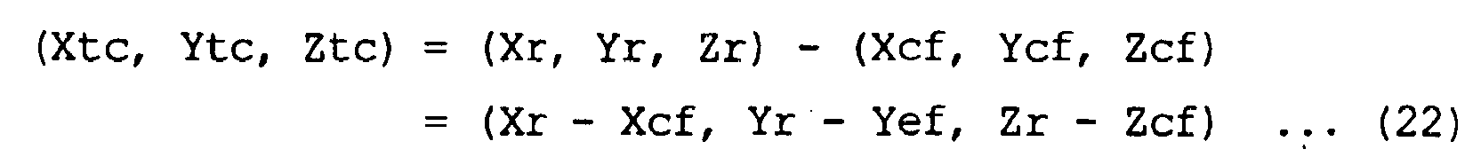
- Because information to be obtained finally is the screen coordinates when the mark M is on the final reaching point, as the relationship in the equation (22) is substituted into the equations (2) and (3) and they are solved for the coordinates (It, Jt) of the moving target point, the coordinates of the moving target point in a load deposition work are obtained as the equations (6) and (7).
- A description will now be given of the automatic fork positioning control and the process of drawing the moving
target point mark 87. - First, when the
forks 2 are lifted at a height exceeding the set height, a process for image recognition of the mark M is carried out based on image data picked up by thecamera 24. That is, image processing to identify the mark M1 is carried out using the template T1 in a load pickup mode and image processing to identify the mark M2 is carried out using the template T2 in a load deposition mode. Then, positional data I, J and D values of the image-recognized mark M on the screen are obtained. - The display
position determining section 84 computes the coordinates (It, Jt) of the moving target point T using the data D value among them. That is, the coordinates (It, Jt) of the moving target point are computed according to the equations (4) and (5) at the time of a load pickup work and the coordinates (It, Jt) of the moving target point are computed according to the equations (6) and (7) at the time of a load deposition work. Those coordinate data (It, Jt) are sent to thedrawing display section 77. Thedrawing display section 77 reads figure data for a display mark from the drawingdata memory section 78 according to an instruction from the displayposition determining section 84 and displays the movingtarget point mark 87 at the coordinates (It, Jt) as shown inFig. 13(a) in such a way as to overlie the image. - On the
screen 28A at the time of a load pickup work, the movingtarget point mark 87 indicating the moving target point T where the mark M1 should reach finally at the time theforks 2 are positioned to thepallet 41 is displayed. On thescreen 28A at the time of a load deposition work, on the other hand, the movingtarget point mark 87 indicating the moving target point T where the mark M2 should reach finally at the time theforks 2 are positioned above theshelf plate 42 by a predetermined distance is displayed. - As the
activation switch 38 of themulti lever 31 is operated, automatic fork positioning control is initiated. The loadhandling control section 47 computes the relative positional coordinates (Xc, Yc, Zc) of thecamera 24 with the mark M as the origin O based on the positional data I, J and D values. Then, to set the vector FP to zero, control amounts for setting both Yc and Zc values to zero is obtained. Then, the loadhandling control section 47 performs current value control of the electromagneticproportional valves proportional valve 68 for side shifting via the solenoid drive circuit 44 based on the control amounts and performs drive control of thelift cylinders side shift cylinder 71, thereby positioning theforks 2. As a result, theforks 2 are moved in the up and down direction by - Zc and moved in the left and right direction by -Yc. - As the
forks 2 are moved, at the time of a load pickup work, for example, the center point of the mark M1 matches with the moving target point T or the center point of the movingtarget point mark 87 and theforks 2 are positioned to the load pickup position that matches with the insertion holes 41A, as shown inFig. 13(b) . At the time of a load deposition work, on the other hand, the center point of the mark M2 matches with the moving target point T and theforks 2 are positioned to the load deposition position that lies above theshelf surface 42A by about 10 to 20 cm. - As the moving target point T to which the mark M should be moved can be seen on the
screen 28A this way, it is possible to easily visually check if theforks 2 are positioned by confirming the coincidence of the center points of the mark M and the movingtarget point mark 87 with each other. At the time of a load carrying work, the driver can also determine whether or not theforks 2 are positioned correctly to an intended load handling target. - The embodiment has the following advantages.
- (1) At the time automatic fork positioning control is executed, the moving
target point mark 87 indicating the moving target point of the mark M affixed to a load handling target is drawn on an image on thescreen 28A. Therefore, the moving target point to which the mark M should be moved at the time of positioning theforks 2 to the load handling target can be visually checked at a glance through thescreen 28A from the drawn position of the movingtarget point mark 87 on thescreen 28A. It is therefore possible to check how theforks 2 are positioned from the process in which the mark M affixed to the load handling target is moved on thescreen 28A toward the movingtarget point mark 87. Then, the completion of the automatic positioning control of theforks 2 can be known through thescreen 28A when both marks M and 87 coincide with each other on thescreen 28A. - (2) As the method of selecting the mark M for position detection (subject to be image-recognized) affixed to a load handling target and drawing the
mark 87 on the moving target point is employed, by paying attention to the two marks M and 87 displayed or drawn on thescreen 28A, the state of positioning theforks 2 can easily be grasped from their positional relationship. - (3) By checking if the mark M matched with the moving
target point mark 87 is on thepallet 41 or on theshelf plate 42, it is possible to easily find out through the image on thescreen 28A whether the positioning of theforks 2 has been successful or failed. - (4) As the deviation amounts between the
forks 2 and theload handling target screen 28A, the driver can see in which direction and how much distance theforks 2 should be moved. - (5) In the automatic fork positioning control, the driver can see the progressing state of the control and can obtain a sense of security in the satisfactory progress of the control and a timely preparation for the next operation at the time of the control is finished.
- (6) As the moving
target point mark 87 is drawn distinguishably between the load pickup mode and load deposition mode, it is possible to cope with both load handling modes. - (7) As the lifting system for lifting the
camera 24 up and down with respect to thecarriage 14, thecamera 24 is moved and placed in two positions, the storage position and the lift-down position, in accordance with the type of the load carrying work (load pickup work, load deposition work). As a result, the image of the work area can be picked up by thecamera 24 placed in the storage position at approximately the same height as theforks 2 at the time of a load pickup work in which there is no load on theforks 2. At the time of a load deposition work in which there is a load on theforks 2, on the other hand, the image of the work area can be picked up by thecamera 24 placed in the lift-down position without being obstructed by the load. Therefore, the image pickup angle for an image displayed on thescreen 28A is convenient for the positioning of theforks 2. - (8) By using the
camera 24 anddisplay device 28 provided to assist a load carrying work at a high place, the movingtarget point mark 87, which becomes a mark for visual confirmation of the moving target point is drawn on thescreen 28A of thedisplay device 28. That is, the position of the mark M is calculated through an image recognition process using image data picked up bycamera 24 and the coordinates of the moving target point are calculated by using the positional data (I, J, D) of the mark M, acquired for automatic fork positioning control, to thereby obtain the drawing position of the movingtarget point mark 87. - Therefore, fewer calculation processes, which are added only for the positional calculation of the moving target point, are required and the load of the CPU for automatic fork positioning control need not be increased much even if a drawing process of drawing the moving
target point mark 87 on thescreen 28A is added. - In the second embodiment, a load handling operation aiding apparatus of a type that has a camera fixed to the mast is adopted.
- As shown in
Fig. 14 , themast 13 comprises theouter mast 13A, themiddle mast 13B and theinner mast 13C in order from the outer side. Abeam 194 is laid horizontally in a position slightly above the height directional center of theinner mast 13C and acamera 195 is fixed to the bottom surface of thebeam 194. Animage pickup section 195A of thecamera 195 faces forward to be able to pick up the image of a work area of theforks 2. -
Fig. 15 shows a part of a load handling apparatus (mast assembly) from the front and shows thecarriage 14 placed in the topmost position of theinner mast 13C. In that state, thecamera 195 is positioned below theforks 2 by a predetermined distance and is positioned in a middle of a pair offorks 2 with thecarriage 14 not side-shifted with regard to the left and right direction (vehicle's widthwise direction). Themast 13 is of a telescopic type (full free type) and does not start protracting until thecarriage 14 reaches the topmost position of theinner mast 13C. When the mast protracts after thecarriage 14 reaches the topmost position of theinner mast 13C, i.e., at a height equal to or higher than a predetermined height after thecarriage 14 reaches the topmost position of theinner mast 13C, therefore, the positional relationship between theforks 2 and thecamera 195 is always kept constant in the up and down direction. - The position of the
camera 195 shown inFig. 15 is approximately equivalent to the position at which the camera is moved down with respect to theforks 2 in the first embodiment. Even at the time of a load deposition work in which a load is placed on theforks 2, the mark M2 affixed to theshelf plate 42 as a load handling target at that time can be picked up by thecamera 195. Of course, at the time of a load pickup work in which no load is placed on theforks 2, the mark M1 affixed to thepallet 41 as a load handling target at that time can be picked up. As apparent from the above, the embodiment differs from the first embodiment only in that thecamera 95 is secured to theinner mast 13C, and thecontroller 45 electrically connected to thecamera 195 performs image processing and load handling control using image data picked up by thecamera 195 as per the first embodiment. - A
stroke sensor 73 is provided on theside shift cylinder 71 and detects the stroke amount of theside shift cylinder 71. The side shifting amount of theforks 2 is grasped from the detection result from thestroke sensor 73 and the relative positional relationship between theforks 2 and thecamera 195 in the left and right direction (Y direction) or the deviation amount between thecamera 195 and theforks 2 in the Y direction is grasped. -
Fig. 16 shows the control circuit of the load handlingoperation aiding apparatus 20. As shown in the diagram, the aidingapparatus 20 basically has the same electrical structure as that of the first embodiment. As thecamera 195 is fixed to theinner mast 13C, however, sensors for the camera lifting apparatus and the actuator become unnecessary and are thus omitted. In the present embodiment, the deviation amount between thecamera 195 and theforks 2 in the Y direction is acquired from the measured value from thestroke sensor 73, and using it, the moving target point and the deviation amounts between theforks 2 and the load handling target in the X, Y and Z directions are computed. - A description will now be given of a method of calculating the moving target point in the present embodiment.
- To position the
forks 2 to thepallet 41 at the time of a load pickup work, the coordinates (It, Jt) of the moving target point to which the mark M1 should be moved on thescreen 28A are given by the following equations as per the first embodiment.

stroke sensor 73. Yp, Zp and Zcf are known values. The center position of a pair of forks is the position at which a bisector of the layout interval of the forks intersects a line passing through the bent portions of the forks. - At the time of a load deposition work, the coordinates (It, Jt) of the moving target point to which the mark M2 should be moved on the
screen 28A to position theforks 2 to the load deposition position R lying above theshelf surface 42A by a predetermined distance (10 to 20 cm) with respect to theshelf plate 42 are given by the following equations.

- Although Ycf is a fixed value for the
camera 24 is attached to theside shifter 16 and moved together with theforks 2 in the first embodiment, Ycf is a variable which varies according to the state of side shifting in this embodiment since thecamera 24 does not move even when theforks 2 are moved sideways by side shifting. Therefore, Ycf used in the equations (4) and (6) is obtained by measurement with thestroke sensor 73. - As the amount of retraction ΔY from the fully protracted state of the
side shift cylinder 71 is measured by thestroke sensor 73 and let Ycf when ΔY = 0 be Ycf0, the variable Ycf is expressed by the following equation.


side shift cylinder 71 is fully protracted, as seen from thecamera 24, ΔY is the retracted amount (measured by the stroke sensor 73) from the fully protracted state of theside shift cylinder 71, and Zcf is the vertical coordinate of the horizontal center of the bases of the forks as seen from the camera. - The second embodiment has the following advantages.
- As the camera is fixed to the
inner mast 13C, it is possible to eliminate the need for the camera lifting apparatus used in the first embodiment so that the image pickup system can be realized with a simple structure and at a low cost. What is more, as the movingtarget point mark 87 is drawn on thescreen 28A, the driver can visually check, at a glance, the moving target point to which theforks 2 should be moved, from themark 87 drawn on the image on thescreen 28A. Therefore, the advantages (1) to (6) and (8) discussed in the first embodiment are also obtained. - The third embodiment differs from the individual embodiments in that automatic control to automatically position the forks is not employed.
Fig. 17 shows the control circuit of a load handling operation aiding apparatus. Thecamera 195 is fixed to theinner mast 13C as per the second embodiment. - Because automatic positioning control is not carried out, the relative coordinate
computing section 85 and the controlamount computing section 86 in the loadhandling control section 47 are omitted. The loadhandling control section 47 is electrically connected withindividual sensors 101 to 104 for detecting the operations of load handling levers provided on the instrument panel in the driver's seat 9, namely, alift lever 96, areach lever 97, aside shift lever 98 and atilt lever 99, and sensors similar to thesensors 58 to 60 and 73 of the second embodiment. The loadhandling control section 47 performs current value control of the solenoids of the electromagneticproportional valves 65 to 69 via thesolenoid drive circuit 50 based on signals from theindividual sensors 101 to 104, and performs drive control of thecylinders individual levers 96 to 99. Thelift lever 96 and theside shift lever 98 constitute manual operation means. - Although the forklift according to the present embodiment is of a manual operation type, which drives and controls the cylinders by manual operation of the levers, the image of a work area at a high place picked up by the
camera 195 is displayed on thescreen 28A of thedisplay device 28. Theimage control section 46 has a structure similar to that of each of the above-described embodiments, and performs mark image recognition process, mark positional data calculating process, a calculating process for a moving target point and a drawing process for positioning information, such as a moving target point mark, based on image data picked up by thecamera 195. - At a height equal to or higher than a predetermined height, therefore, the moving
target point mark 87 indicating the moving target point of theforks 2 is drawn on thescreen 28A. Therefore, the image of a work area at a high place is displayed on thescreen 28A and the moving target point can be visually checked from themark 87 when the positioning of theforks 2 is manually done while viewing thescreen 28A. The deviation amounts between theforks 2 and theload handling target screen 28A. Therefore, the advantages (2) and (4) to (6) can be obtained as per each of the above-described embodiments. - According to the present embodiment, the driver can reliably position the
forks 2 to theload handling target forks 2 and theload handling target screen 28A, become "0". This can improve the efficiency of a load carrying work in a position that is difficult to see with eyes, such as a highly lifted place. - The embodiment is not limited to what is described above but can be worked in the following modes.
- In each of the above-described embodiments, whether the content of the load carrying work is a load pickup work or a load deposition work is discriminated based on the detected value from the load weight sensor, according to the type of the discriminated load carrying work, and the target mark M is determined to decide whether the load handling target is a pallet or a shelf plate. Instead, a method of providing a button to be operated to designate a load carrying work on, for example, the instrument panel in the driver's seat and designating the type of the load carrying work to the controller by a driver's operating the button can be employed.
- The target for an image recognition process (to-be-subjected-to-image-recognition target) based on image data picked up by the camera is not limited to the mark M1, M2 affixed to the load handling target. For example, a scheme of performing an image recognition process with the shape or the like of the
pallet 41 or theshelf plate 42 as a pattern and calculating the position of the load handling target can be employed, too. - The design of the moving
target point mark 87 is not limited to those of the above-described embodiments. Any shape that can specify a moving target point is sufficient. For example, a figure whose shape has directivity, such as an arrow figure indicating a moving target point can be used. A mark with a predetermined shape, such as a circle, triangle, rectangle and polygon, may be drawn in such a way that the barycenter coincides with the moving target point. A mark to be displayed on the screen as a mark indicating a target moving point can take any design or figure. For example, it may be a "cross", "point", "line" or the like. If it is cross lines, for example, positioning has only to be done in such a way that the barycenter of the mark M coincides with two vertical and horizontal lines constituting the cross lines, so that an operation to position the forks is easy in case of the manual operation type. Further, it may be a radial figure, other line figures and illustrations. A figure which has a point symmetrical property as used in each of the above-described embodiments is however preferable because it is easy to specify a point. A mark (target point sign) is not limited to a still picture but may be a moving picture. The mark may be flickered or its color may be changed with the passage of time. Because the positional range where the forks can be inserted into the holes of a pallet can be regarded as a positioning range, the display color of the sign may be changed, when the forks are positioned within this positioning range, to visually notify a driver to that effect. - If a driver can be visually notified of the moving target point, it should not necessarily be limited to displaying a mark in the position of the moving target point. For example, a scheme of drawing two signs separately indicating the I coordinate and J coordinate of the moving target point along two vertical and horizontal sides of the
screen 28A and specifying the moving target point on the screen by specifying the I coordinate and J coordinate from both signs can be employed. - Although a radial figure is used as an image recognition mark, it is not limited to such a figure. It may be a simple figure, such as a rectangle (■) or a triangle (▲). While it is necessary to prepare multiple templates depending on the pattern matching, which takes time in an image recognition process, the position of a load handling target can be detected. An image recognition method other than pattern matching may be used to detect the position of a load handling target. It is possible to employ a method of acquiring the coordinates of a moving target point using a method other than image recognition. For example, a method of detecting the position of a load handling target by detecting a to-be-detected portion affixed to a load handling target, such as a pallet or a shelf portion (shelf plate), can be employed.
- As positioning information, information is sufficient which shows the direction and the deviation amount at the time of positioning a load carrying apparatus to a load handling target. That is, unlike in the above-mentioned embodiment, it need not be the distance itself to which the
forks 2 are to be shifted for positioning. For example, a gauge indicating the shift amount for positioning in the YZ directions as a relative amount with the screen scale being 100 may be drawn. - Although the moving
target point mark 87 in each of the above-described embodiments is the moving target point of the mark M on thescreen 28A, it should not necessarily be the moving target point of the mark M. For example, with ahole 41A in one side of the pallet 41 (e.g., the right-hand side) taken as a reference, a moving target point mark indicating the moving target point of thehole 41A may be drawn. In short, it is sufficient to set a reference point convenient at the time of positioning a load carrying apparatus to a load handling target somewhere and draw a sign indicating a moving target point to which the reference point should be moved at the time of positioning the load carrying apparatus to the load handling target. The reference point may be set anywhere outside the vehicle as long as it performs the role, and it can be a part of the load handling target, a specific location around the load handling target (e.g., a specific location of a rack), or a mark affixed to the part or the locations. In case where the reference point is a mark, a mark for image recognition should not necessarily be used as the mark but a mark for the reference point can be provided separate from the mark M1, M2. - Although the
forks 2 can be positioned in the up and down direction and left and right direction with the moving target point mark in each of the above-described embodiments, a moving target point mark which can position only in one direction in up and down or left and right may be displayed on the screen. - In case of manual operation to position the forks as in the third embodiment, it is necessary to manipulate the forks in the up and down direction and left and right direction. At this time, a method of indicating positions, if matched in the moving direction in each of the up and down direction and left and right direction, in a display mode visually indicating to that effect or notifying it by sounds is employed.
- In the third embodiment, the
camera 24 may be provided on theinner mast 13C in a liftable manner. That is, thecamera 24 is attached to the beam of theinner mast 13A in a liftable manner between two positions equivalent to the storage position and lift-down position in the first embodiment in the relative positional relationship between thecamera 24 and theforks 2. An image is picked up by thecamera 24 placed in the storage position at the time of a load pickup work and is picked up by thecamera 24 placed in the lift-down position at the time of a load deposition work. - The detection means that acquires positional information of a load handling target is not limited to image processing of image data picked up by the camera. For example, a method of measuring the position of a load handling target from a detected value from an ultrasonic sensor, proximity sensor, a laser sensor or the like in use and calculating the deviation amount or the moving target point can be used. In this case, a mark as a to-be-detected target is affixed to a load handling target and the moving target point of the mark can be used as a drawing position of the moving target point mark. In case of employing a sensor-based position detection method other than image processing, the camera may be used together or may be eliminated. In case of eliminating the camera, for example, it is possible to display numerical values in the XYZ directions on the screen of the display device or draw only a mark showing the positional relationship between the load handling target and the moving target point. Even in case where there is a camera, a picked-up image may be used only in position detection, and likewise, only numerical values or only a mark may be drawn on the screen.
- In each of the above-described embodiments, the mark M affixed to a load handling target is matched with the moving
target point mark 87 on the screen as a method of supporting fork positioning. By way of contrast, it is possible to employ a method of drawing a mark indicating the current fork position, in place of a picked-up mark, on the screen in the proper position and drawing another mark at the moving target point corresponding to that mark to thereby support fork positioning from the positional relationship between the two drawn marks. - Although the deviation amounts (moving distances) in the three directions (XYZ directions) are displayed in each of the above-described embodiments, only the YZ directions or the Z direction may be displayed.
- It is not limited to an industrial vehicle in which forks are provided movable in the vehicle's widthwise direction. For example, it may be adapted to a forklift that does not have a side shift function.
- The load carrying apparatus is not limited to forks. It may be an attachment other than the forks. It may be a clamping apparatus, which firmly holds a load or a bucket for scooping a load. Further, it may be a load carrying apparatus, which holds a load with magnetic force.
- The industrial vehicle is not limited to reach type forklift. It may be a counter balance type forklift. Further, the industrial vehicle is not limited to a forklift. For example, it may be a power shovel. A load to be a target for a load carrying work is not limited to a pallet or a load that is handled on a pallet, but may be a log, a roll of paper, a container, or a fluid or the like, such as sediment, which is handled in a work by industrial vehicles. The load includes a member on which a load is deposited and a load container box other than the pallet.
- The fourth embodiment of the present invention will be described mainly on those that differ from the above-described embodiments according to
Figs. 18 to 21 . In this embodiment, a load carrying apparatus performs a predetermined operation in accordance with the type of a load carrying work. To simplify the description, same reference symbols are given to those constituents that are the same as those of each of the above-described embodiments and their detailed descriptions will be omitted. -
Fig. 18 shows marks and templates.Fig. 18(a) shows the mark M1 for pallet position detection andFig. 18(c) shows the mark M2 for rack position detection.Fig. 18(b) shows the template T1 for the mark M1, andFig. 18(d) shows the template T2 for the mark M2. The designs of the marks M1 and M2 in this embodiment are the same as those of the embodiment inFig. 5 except that their white and black are inverted to those of the designs of the marks in the embodiment inFig. 5 . - The
height sensor 58 shown inFig. 4 detects if theforks 2 are at or higher than a set height (height), and is comprised of a switch whose ON/OFF is switched at, for example, the set height. The automatic fork positioning control is executed only when the detected height of theheight sensor 58 is equal to or greater than the set height. Theheight sensor 58 may be a sensor capable of continuously detecting the height of theforks 2. For example, a reel type height sensor which detects the amount of rotation of a reel from and on which a wire is fed out and wound in accordance with the elevation of thecarriage 14 and an ultrasonic height sensor which detects the stroke of a cylinder from the measured time by which an ultrasonic wave that propagates in a fluid in the lift cylinders 15 is reflected at a piston and returned can be employed as theheight sensor 58. - The
load weight sensor 59 detects the weight of theload 43 placed on theforks 2, and is comprised of a pressure sensor which detects the hydraulic pressure in thelift cylinder 15B in the present embodiment. Theload weight sensor 59 sends out a signal of a voltage value according to the weight of theload 43 on theforks 2. - The load
handling control section 47 determines "a load present" when a detected value W of theload weight sensor 59 exceeds a predetermined threshold value Wo and determines "no load" when the detected value W is equal to or smaller than the threshold value Wo. As the detected value W of theload weight sensor 59 includes the weight component of thecarriage 14 or the like, a detected value at the time of an empty load or a value added with a small value to that detected value is set as the threshold value Wo. For example, it is desirable to set the threshold value Wo in such a way that "load present" is judged when only thepallet 41 is loaded. - The load
handling control section 47 enters a standby mode for the activation of the automatic positioning control of the forks only when it is determined that a height condition (height H ≥ 2 (m)) in which the height of theforks 2 which is grasped from the detected value of theheight sensor 58 is equal to or greater than the set height (e.g., about 2 meters) is satisfied. After entering the activation standby mode, the loadhandling control section 47 determines whether or not there is aload 43 placed on theforks 2 based on the detected value from theload weight sensor 59. When having judged that it is "no load", the loadhandling control section 47 determines that a load carrying work to be done thereafter is a load pickup work and sets the "load pickup mode", and when having judged that it is "load present", it determines that a load carrying work to be done thereafter is a load deposition work and sets the "load deposition mode". The setting process of the load handling mode is performed every predetermined time (e.g. several tens milliseconds) - The
camera unit 23 is placed in the storage position when the height H of theforks 2 is less than 2 m. When it is the "load pickup mode" during the activation standby mode (height H ≥ 2 m), the loadhandling control section 47 places thecamera unit 23 in the storage position, whereas in the "load deposition mode", it places thecamera unit 23 in the lift-down position. The driving of theelectric actuator 61 that has been activated to move thecamera unit 23 is stopped when thecamera unit 23 reaches the upper-limit position and the upper-limitposition detection switch 52 is switched on and is stopped when thecamera unit 23 reaches the lower-limit position and the lower-limitposition detection switch 53 is switched on. This causes thecamera unit 23 to be placed in two positions, the storage position and the lift-down position, and the image of a load carrying work area in front of the forks is picked up by thecamera 24 from those two positions. - The
camera unit 23 is switched between the storage position and the lift-down position in accordance with the "load pickup mode" and "load deposition mode". The reason is that although it is desirable to pick up an image from approximately the same height as the load deposition portion of theforks 2, while there is no load on theforks 2 at the time of load pickup so that an image can be picked up even if thecamera 24 is positioned at approximately the same height as theforks 2, if thecamera 24 is positioned at approximately the same height as theforks 2 at the time of load deposition, the load placed on theforks 2 obstructs and the image of the load carrying work area cannot be picked up. In this respect, thecamera 24 is placed in the storage position at approximately the same height as theforks 2 in "load pickup mode" while in "load deposition mode", thecamera 24 is placed in the lift-down position separated below theforks 2 by a predetermined distance so that the load does not interfere with image pickup. - The automatic fork positioning control is used in a load carrying work at a high place where the
forks 2 are positioned at a height of 2 meters or higher. The driver manipulates theknob 35 of themulti lever 31 to lift theforks 2 up and roughly position theforks 2 with respect to the targeting load handling target 41 (42) while viewing the screen of thedisplay device 28. When theactivation switch 38 is operated in the state where the mark M1 (M2) affixed to the load handling target 41 (42) to be a target is displayed on the screen, the automatic fork positioning control is initiated. - The
tilt angle sensor 60 detects a tilt angle with an angle at which theforks 2 are in a horizontal state as a reference, and is comprised of, for example, a potentiometer. At the time the automatic fork positioning control is performed, the loadhandling control section 47 controls driving of thetilt cylinder 72 in such a way that theforks 2 are positioned horizontal based on a detected value from thetilt angle sensor 60. - When receiving a signal indicative of the manipulation of the
activation switch 38, the loadhandling control section 47 instructs theimage control section 46 to start the automatic positioning control of theforks 2 via communications. Theimage control section 46 receives from the loadhandling control section 47 activation instruction data to initiate the image recognition process and load handling mode data indicating whether it is the load pickup mode or the load deposition mode. - The
image control section 46 has adisplay processing section 75, animage processing section 76, adrawing display section 77, a drawingdata memory section 78 and avoice synthesizing section 79. Thedisplay processing section 75 sends out a video signal input from thecamera 24 to thedisplay device 28 in such a way that the image picked up by thecamera 24 is displayed on the screen. Thevoice synthesizing section 79 performs voice synthesizing process for voice guidance or the like and outputs a voice signal to thespeaker 51. Image data from thedisplay processing section 75 is input to theimage processing section 76. - The
image processing section 76 performs an image recognition process to compute the position of the mark M1, M2 on the screen and computes the positional relationship between the vehicle (forks 2) and the load handling target based on the computed position of the mark M1, M2. Theimage processing section 76 has an imagerecognition processing section 81, atemplate memory section 82, animage computing section 83 and a displayposition determining section 84. - The image
recognition processing section 81 performs an image recognition process based on a pattern matching process. Theimage computing section 83 computes the positional coordinates of the mark M1 (M2) in the screen coordinate system from the result of the image recognition process. - A start command for the image recognition process and load handling mode data or the like sent to the
image control section 46 from the loadhandling control section 47 are input to theimage processing section 76. In theimage processing section 76, upon reception of those data, an image recognition process is performed by the imagerecognition processing section 81 and a control amount calculating process for automatic fork positioning control is executed by theimage computing section 83, the relative coordinatecomputing section 85 and the controlamount computing section 86 by using the result of the image recognition process. - First, upon reception of the start command data, the image
recognition processing section 81 executes the image recognition process of one of the marks M1 and M2 based on the load handling mode data input together then. That is, the imagerecognition processing section 81 performs an image recognition process with the mark M1 for pallet position detection as a recognition target when the load handling mode recognized based on the load handling mode data is the load pickup mode and performs an image recognition process with the mark M2 for rack position detection as a recognition target when it is the load deposition mode. Stored in thetemplate memory section 82 are a template T1 which is used in a pattern matching process with the mark M1 as a recognition target and a template T2 which is used in a pattern matching process with the mark M2 as a recognition target (seeFig. 18 for both). At the time of executing a pattern matching process, theimage processing section 76 uses the template T1 when it is the load pickup mode and uses the template T2 when it is the load deposition mode. This image recognition process is equivalent to a process that is executed by the control means based on the decision result from the decision means. -
Fig. 19 shows the screen coordinate system set on the screen. In the screen coordinate system, the coordinates are treated pixel by pixel, and in the diagram, H is the number of horizontal pixels of thescreen 28A and V is the number of vertical pixels of thescreen 28A. The imagerecognition processing section 81 performs matching with respect to the two patterns P1, P1 (P2, P2) constituting the mark M1 on image data at two locations using the template T1 (T2) and recognizes each pattern P1, P1, as shown inFig. 19(b) . Theimage computing section 83 computes coordinates (I1, J1), (I2, J2) of the center points (radial center points) of the individual patterns P1, P1 recognized by the imagerecognition processing section 81 and acquires a barycenter (I, J) of the mark M1 and a center distance D between the two patterns P1, P1 based on those two coordinate values. - The display
position determining section 84 performs a process of computing a display position (drawing position) for drawing on the screen of thedisplay device 28. The displayposition determining section 84 computes the drawing position for the contour of the mark and the drawing position of a target mark to be a moving target point of the mark M1 (M2) at the time of positioning theforks 2 to a load handling target. When receiving drawing position data from the displayposition determining section 84, thedrawing display section 77 reads drawing data (image data or the like) corresponding to the drawing content from the drawingdata memory section 78 and sends a drawing signal to thedisplay processing section 75 to display the drawing content in the designated drawing position on the picked-up image in such a way that it is overlapped in the designated drawing position on the picked-up image. Thevoice synthesizing section 79 generates a voice guidance for the driver from thespeaker 51, as needed, in synchronism with the drawing timing. - The data (I, J, D) computed by the
image computing section 83 is sent to the loadhandling control section 47 from theimage control section 46. The loadhandling control section 47 has the relative coordinatecomputing section 85 and the controlamount computing section 86. The loadhandling control section 47 computes control amounts (the amounts of movement in the Y and Z directions) needed to position theforks 2 to the load handling target. The calculation method is the same as that of the above-described embodiment. - The load
handling control section 47 stores the program of a load carrying work determining routine as shown in a flowchart inFig. 20 . This routine is executed by a CPU in the loadhandling control section 47. The CPU executes the lifting control of the camera and automatic positioning control of the forks in accordance with the result of the decision in each routine. In the routine, the CPU determines whether a load carrying work to be conducted next as a result of the operation of theactivation switch 38 is a load pickup work, or a load deposition work, and the lifting control of the camera and automatic fork positioning control according to the type of the load carrying work. The automatic fork positioning control is equivalent to automatic load handling control and aiding control to aid it is the camera lifting control. - The following will discuss the load carrying work determining routine which is executed by the CPU of the load
handling control section 47 based onFig. 20 . - First, in step (hereinafter simply written as "S") 10, the CPU acquires the detected value from the
load weight sensor 59. - In S20, it is determined whether or not the load weight W exceeds the threshold value Wo. When the load weight W ≤ Wo is met, the process proceeds to S30 and when the load weight W > Wo is met, the process proceeds to S40.
- In S30, it is determined that the load carrying work to be carried out next is a "load pickup work".
- In S40, it is determined that the load carrying work to be carried out next is a "load deposition work".
- The CPU always judges the contents of the load carrying work by executing this routine every interval of a predetermined time, and allows the
forks 2 to carry out a load handling operation according to the decision result when the height is equal to or higher than 2 m and theactivation switch 38 is operated. That is, when the height is equal to or higher than 2 m and theactivation switch 38 is operated, a load handling operation to place theforks 2 in the "load pickup position" is performed if the decision result is a load pickup work, while a load handling operation to place theforks 2 in the "load deposition position" is performed if the decision result is a load deposition work. -
Fig. 21 illustrates a load handling operation based on automatic fork positioning control, andFig. 21(a) shows a state in which the forks are placed in a load pickup position, andFig. 21(b) shows a state in which the forks are placed in a load deposition position. When the detected value (load weight) from theload weight sensor 59 is equal to or smaller than the threshold value Wo (W ≤ Wo), as described above, it is determined that the load carrying work to be done next is a "load pickup work", and theforks 2 are placed in the load pickup position shown inFig. 21(a) . At this time, as the template T1 is read and an image recognition process of the mark M1 for pallet position detection is carried out, the position of the mark M1 is acquired and the relative coordinates (Xc, Yc, Zc) of the mark M1 and thecamera 24 are acquired based on data (I, J, D) that is determined from that mark position. The individual controls amounts in the up and down and the left and right directions determined from the relative coordinates (Xc, Yc, Zc) are instructed to thecontrol valve 65. As a result, theforks 2 are placed in a state where they face theholes 41A of thepallet 41 as shown inFig. 21(a) . At this time, theforks 2 are positioned at a height Ht. - When the detected value (load weight) W from the
load weight sensor 59 exceeds the threshold value Wo (W > Wo), on the other hand, it is determined that the load carrying work to be done next is a "load deposition work", and theforks 2 are placed in the load deposition position shown inFig. 21(b) . As the template T2 is read and an image recognition process of the mark M2 for rack position detection is carried out, the position of the mark M2 is acquired and the relative coordinates (Xc, Yc, Zc) of the mark M2 and thecamera 24 are acquired based on data (I, J, D) that is determined from that mark position. To place theforks 2 in the load deposition position for theshelf plate 42, the individual controls amounts in the up and down and the left and right directions determined from the relative coordinates (Xc, Yc, Zc) are instructed to thecontrol valve 65. As a result, theforks 2 are placed at a height Hp positioned above theshelf surface 42A by a predetermined distance ΔL as shown inFig. 21(b) . - Prior to that, when the height H of the
forks 2 reaches 2 m or higher and the activation standby mode is entered, the lifting control of the camera is started. The camera lifting control is started by a signal input from theheight sensor 58 when the height H of theforks 2 reaches the height of 2 m. At this time, it is also determined based on the detected value from theload weight sensor 59 whether or not the load carrying work to be done next is a load pickup work or a load deposition work. Theheight sensor 58 constitutes the detection means that outputs a signal to be used in determining if the start condition for the camera lifting control as aiding control is satisfied. - While the contents of the camera lifting control program is almost the same as the routine in
Fig. 20 , inputting of a signal from theheight sensor 58 indicating that the height 2 m has been reached in place of the operation of theactivation switch 38 is the condition to start that program. When load weight W ≥ Wo, it is determined that a load carrying work to be done next is a "load pickup work" and thecamera unit 23 is placed in the storage position. When the load weight W < Wo, on the other hand, it is determined that a load carrying work to be done next is a "load deposition work" and thecamera unit 23 is placed in the lift-down position. During this control, theelectric actuator 61 is activated only when it is necessary to move thecamera unit 23. - The present embodiment has the following advantages.
- (1) As the
activation switch 38 is operated, thecontroller 45 makes a decision on whether the load carrying work to be done next is a load pickup work or a load deposition work based on the detected value from theload weight sensor 59. Then, control of the load handling operation is executed according to the type of the determined load carrying work. It is therefore possible to simplify the driver's operations needed for a load carrying work as much as possible. - (2) When the height condition (H ≥ 2 m) is met, camera lifting control is started according to the signal from the
height sensor 58 and thecamera unit 23 is placed in a position according to the type of the load carrying work. At this time, thecontroller 45 also makes a decision on whether the load carrying work to be done next is a load pickup work or a load deposition work based on the detected value from theload weight sensor 59 and thecamera unit 23 is placed in the position according to the type of the determined load carrying work. This makes it unnecessary for the driver to notify thecontroller 45 of which work the load carrying work to be done next is, so that the driver need not perform any operation for the camera lifting control. - (3) The decision on whether or not there is a
load 43 on theforks 2 is executed based on the detected value from theload weight sensor 59. Therefore, thesensor 59 is not easily broken and has a high reliability as compared with the structure that determines the presence/absence of a load by means of a contact type switch,_such as a limit switch. - The fifth embodiment will be described next. This embodiment is an example adapted to an automatic elevation unit equipped on an industrial vehicle. The automatic elevation unit is a unit that registers height data of forks in a memory beforehand in association with an operation button and performs control to automatically lift up the forks to a height corresponding to the button when operated.
- As shown in
Fig. 22 , the instrument panel of theforklift 1 is provided with acontrol panel 90 to place theforks 2 automatically in a predetermined position by a separate operation from theknob 35 of themulti lever 31. - The
control panel 90 is comprised of aset key 91, threenumber keys 92a to 92c, a stockingkey 93, ashipment key 94, ahorizontal key 95, aheight limiting key 126, a stop key 197 andLEDs 198 provided adjacent to the individual keys. - The
set key 91 is used when the height position of theforks 2 is set or when the height limit position of theforks 2 is set at the time of doing shipment (load pickup) or stocking (load deposition) is performed. Thenumber keys 92a to 92c are used when the height position of theforks 2 is set or when theforks 2 are automatically lifted up and can distinguish three height positions by numbers "1, 2, 3". - The stocking
key 93 is used when theforks 2 are automatically lifted up for lad deposition with a load placed on theforks 2 or when the height position is set. Theshipment key 94 is used when theforks 2 are automatically lifted up or when the height position is set at the time of picking up a load stored at a predetermined height. The height position can be set distinguishably for each type of the load carrying work. In this embodiment, the stockingkey 93 and theshipment key 94 are used only when the height position is set. Of course, the stockingkey 93 and theshipment key 94 can be eliminated by employing a method of automatically setting the load deposition height to a position set apart above the load pickup height by a predetermined distance when any of thenumber keys 92a-92c is selected and the load pickup height (load pickup height) is set. -
Fig. 23 shows the electrical structure of the automatic elevation unit. In the present embodiment, the structural portions of the camera lifting control system and the image control system according to the first embodiment are omitted and thecontrol panel 90 is connected to the input side of the loadhandling control section 47 instead. The structural portion of the load handling system is the same as that of the first embodiment.Height sensor 58 can be used continuously to detect the height. - Although the height of the
forks 2 slightly differs between a load deposition work and a load pickup work, the presence/absence of aload 43 on theforks 2 is detected based on the detected value from theload weight sensor 59. Then, it is determined that the load carrying work is a load deposition work (stocking) in case of no load (load weight W ≤ threshold value Wo) and it is determined that the load carrying work is a load pickup work (shipping) in case of the presence of a load (load weight W > threshold value Wo). The routine for determining the load carrying work is the same as the process of the flowchart inFig. 20 . The threenumber keys 92a to 92c, instead of theactivation switch 38, constitute the start operation means, and theforks 2 are lifted up to that one of the load pickup position and load deposition position, preset for each number key, which is determined by the detected load weight. - The
height limiting key 126 is used when the elevation height of theforks 2 is restricted at the time of operating themulti lever 31 or automatic lifting. Theindividual LEDs 198 are controlled to be turned on, or flickered by thecontroller 45 in association with the depression of each key at the time of setting the height position, at the time of an automatic lifting operation, at the time of setting the height limit, at the time of a horizontal stop operation, etc. - The load
handling control section 47 of thecontroller 45 has amemory 47A. Target position data set through thecontrol panel 90 is stored beforehand in thememory 47A. The target position data includes load deposition target position data and load pickup target position data for a single storage section of therack 40. - In case where the
forks 2 are lifted up to the target position under automatic lifting control, one of thenumber keys 92a to 92c which corresponds to that target position is depressed. The loadhandling control section 47 determines the presence/absence of a load based on the detected value from theload weight sensor 59, reads load deposition target position data corresponding to the depressed number key (one of 92a-92c) when it is determined that there is a load, and reads load pickup target position data corresponding to the depressed number key (one of 92a-92c) when it is determined that there is no load. - The
controller 45 activates thecontrol valve 65 to drive thelift cylinders 15A, B in such a way as to move theforks 2 to the target position. While thelift cylinders handling control section 47 detects the height position of theforks 2 every predetermined time based on the detection signal from theheight sensor 58. - When the
forks 2 reach a height before the target position by a predetermined distance, the loadhandling control section 47 controls the current value of theelectromagnetic control valve 66 to stop the protracting actions of thelift cylinders forks 2 are stopped in the target position. That.is, it is stopped in the load deposition position (Fig. 21(b) ) if there is aload 43 on theforks 2, and load deposition is carried out at that height. It is stopped in the load pickup position (Fig. 21(a) ) if there is noload 43 on theforks 2 and load pickup is carried out at that height. When the work is done, theforks 2 are moved from that height position. In case where it is followed by execution of automatic height control, for example, one of thenumber keys 92a to 92c is depressed next in that state unchanged to move theforks 2 to the next target position. - This embodiment has the following advantage.
- As one of the
number keys 92a to 92c is depressed, it is possible to lift theforks 2 up with one of the "load pickup position" and "load deposition position" as the target position based on the detected value from theload weight sensor 59. It is therefore unnecessary for the driver to determine whether the work to be done next is a load pickup work or a load deposition work and then select a key, but it is sufficient to depress one of thenumber keys 92a to 92c which is of the desired height. - The embodiment is not limited to the above-described one, but may be embodied in the following forms.
- The control contents of automatic load handling control is not limited to the automatic fork positioning control or automatic lifting control in each of the above-described embodiments. For example, the speed of the load carrying apparatus may be controlled in such a way that when it is determined, based on the detected load weight, that a "load pickup work" should be done, the lift-up speed of the load carrying apparatus is increased. When it is determined, based on the detected load weight, that a "load deposition work" should be done, the lift-up speed of the load carrying apparatus is dropped.
- The load detection means is not limited to the load weight sensor. This load detection means may be a limit switch to be provided on, for example, the forks. Alternatively, another sensor which detects a load placed on the forks may be used as well. For example, a non-contact type sensor, such as a proximity sensor, which detects a load in a non-contact manner, may be used. Further, it is possible to detect the presence/absence of a load on the forks based on an image picked up by the camera. For example, means is provided for identifying the bottom shapes of the forks through an image. It is determined that there is no load (load pickup work) when the bottom shapes of the forks can be identified, and it is determined that there is a load (load deposition work) when the bottoms of the forks are hidden by a load and the bottom shapes of the forks cannot be recognized.
- When a limit switch or a proximity switch is used, a signal to be output from the switch is an ON/OFF signal. When the output signal of the switch is an ON signal indicating the detection of a load, for example, the decision means judges that it is a load deposition work and allows a load handling operation or an aiding operation according to the load deposition work to be carried out. When the output signal is an OFF signal indicating that a load has not been detected, the decision means judges that it is a load pickup work and allows a load handling operation or an aiding operation according to the load pickup work to be carried out.
- In the above-mentioned embodiment, camera lifting control is started by using a signal when the height condition (height H ≥ 2 m) is satisfied, i.e., when the
height sensor 58 detects the height H being reached 2 m, as an instruction signal. Instead, the operation signal of theactivation switch 38 may be used as instruction signal to start camera lifting control. In this case, although the moving time of thecamera unit 23 delays automatic load handling control, a work can still be done with the operation of the activation switch alone. - In the above embodiment, automatic fork positioning control is started with the operation signal of the
activation switch 38 as an instruction signal. Instead, automatic fork positioning control may be started when it is determined that the start condition is satisfied based on the signal output from the sensor that serves as the detection means. It is to be noted however that the sensor does not detect the operation by a driver. For example, a given time (e.g., 0.3 sec) passes after the forks are lifted up to a predetermined height and stopped, the CPU initiates the automatic fork positioning control. Then, the automatic fork positioning control is executed targeting the mark closest to the stopped forks (one of the marks M1 and M2 which corresponds to the detected load weight). In this case, the detection section that detects the stop of the forks and the timer (counter) that measures the time after the stop constitute the detection means. - The automatic elevation unit is constructed in such a way that a plurality of heights are stored in the memory beforehand and the target height at which the forks are to be lifted is specified by a button operation. By way of contrast, control may be employed which places the forks at a rough height through the operation of the operation lever, automatically calculates the adequate position from a plurality of target positions stored in the memory and places the forks at the adequate target height. That is, the height sensor detects the height at which the forks are placed by the operation of the operation lever by the driver, that height in the height data stored in the memory which is the closest to the detected height is determined as the height intended by the driver, and the lift cylinder is controlled in such a way as to place the forks in the load pickup position or load deposition position for the height intended by the driver. While this structure does not perform automatic elevation, if the driver performs rough positioning of the forks at a temporary height and always operates the same single switch, decision on whether it is a load pickup work or a load deposition work is executed based on the detected value from the load weight sensor and the forks are automatically positioned in the adequate position according to the decision result.
- Start instruction means is not limited to a switch, but a height may be designated with a voice input. For example, the driver can wear a headphone type microphone and can inform the controller of information designating the height, such as the number of shelves of the rack, in a voice input through the microphone.
- A load handling operation after positioning a load carrying apparatus can also be controlled automatically. For example, a structure can be employed which positions the forks and then automatically performs a load pickup operation or a load deposition operation which is accompanied with forward/backward movement of the forks. That is, if the decision is load pickup, after the forks are positioned, the forks are reached to be inserted into the holes of a pallet, then lifted up by a predetermined amount (e.g., about 10 to 20 cm) to lift a load up, then pulled backward to unload the load from the rack. If the decision is load deposition, on the other hand, after the forks are positioned, the forks are reached to push a load on the forks forward, then lifted down by a predetermined amount (e.g., about 10 to 20 cm) to place the load on the rack, then pulled backward.
- The use of the marks is not limited to the use of two types for load pickup and load deposition. A method that affixes a single mark for load pickup and load deposition in common to, for example, a shelf portion, can be used. When using this method to acquire the target position of the forks at the time of load pickup, for example, the position of the shelf portion can be known by identifying the mark, and computing the height of the holes of a pallet placed on the shelf surface from the position of the shelf portion to be the target position of the forks.
- It is not limited to making such a decision that it is load pickup when there is a load and it is load deposition when there is no load. When the timing of the start switch is set to operate immediately after a load pickup or load deposition, and when the operation of the load carrying apparatus is started by the start switch, it is possible to decide that it is a load deposition work when there is a load and it is a load pickup work when there is no load. The operation of moving the forks backward may be automatically carried out when the activation switch is operated after load pickup with the forks is completed and the operation of moving the forks backward may be automatically carried out when the activation switch is operated after load deposition with the forks is completed.
- The sixth embodiment of the present invention will be described mainly on those that differ from the above-described embodiments according to
Figs. 24 to 29 . The present embodiment relates to a work mode switching apparatus, which sets the mode in accordance with a load carrying work. To simplify the description, same reference symbols are given to those constituents that are the same as those of each of the above-described embodiments and their descriptions will be omitted. -
Fig. 24 shows the state of a load carrying work by the forklift equipped with thecamera 24. The load carrying work forloads 43 is carried out with the loads placed onpallets 41. Arack 40 where theloads 43 are to be placed has a multi-stage structure and some has an overall height equal to or higher than the height of the forklift. If therack 40 has such a height, there may be a case where the driver cannot see the load carrying work from the driver's seat 9 at the time of doing a load carrying work at ashelf plate 42 at a high place. To solve it, the forklift equipped with thecamera 24 picks up the image of an area in front of theforks 2 by thecamera 24 and automatically positions theforks 2 based on the picked-up image, thereby supporting the load carrying work. -
Fig. 25 shows the driver's seat 9 of the forklift. An instrument panel is provided on the front portion of the driver's seat 9. Laid out on the instrument panel are thelift lever 96, thetilt lever 99, thereach lever 97, theside shift lever 98 and anaccel lever 110. Theforks 2 are moved in the up and down direction by the operation of thelift lever 96, are moved in the forward and backward direction by the operation of thereach lever 97, are moved in the left and right direction by the operation of theside shift lever 98, and are tilted by the operation of thetilt lever 99. Those levers 96 to 98 are equivalent to load handling levers. - The
lift lever 96 has alever body 96a and a grip portion (knob) 111 is formed on the upper portion of thelever body 96a. Anactivation switch 112 is provided on atop surface 111a of thegrip portion 111 and, as theactivation switch 112 is depressed, theforks 2 automatically start moving and are positioned. Amode changeover switch 113 as switching means is provided on aside surface 111b of thegrip portion 111. The operation mode of automatic fork positioning control is switched between a load pickup mode for picking up a load and a load deposition mode for placing a load in a predetermined position by depressing themode changeover switch 113. -
Fig. 26 shows the control circuit of the forklift. The load handlingoperation aiding apparatus 20 has acontroller 45, which has theimage control section 46, the loadhandling control section 47 which constitutes control means and work mode setting means, thedrive circuits solenoid drive circuit 50. Thecamera 24 is connected to the input side of theimage control section 46, and thedisplay device 28 and thespeaker 51 are connected to the output side of theimage control section 46, so that a video image is displayed on thescreen 28A (seeFig. 28 and Fig. 29 ) of thedisplay device 28, based on the video signal (image signal) from thecamera 24, or a predetermined announcement is made from thespeaker 51. - Meanwhile, the load
handling control section 47 is connected with the upper-limitposition detection switch 52, the lower-limitposition detection switch 53,potentiometers 96a to 99a of thelevers 96 to 99, theactivation switch 112, themode changeover switch 113, theheight sensor 58, theload weight sensor 59, as detection means (load weight detection means), thestroke sensor 73, thetilt angle sensor 60, etc. The loadhandling control section 47 is connected with theelectric actuator 61 and load handling motor (electric motor) 62 via thedrive circuits electromagnetic selector valves 65 to 69 attached to theoil control valve 64 via thesolenoid drive circuit 50. - Based on signals from the
individual potentiometers 96a to 99a, the loadhandling control section 47 performs current value control of theelectromagnetic selector valves 65 to 69 and drive control of theload handling motor 62. As theload handling motor 62 is operated, the load handling pump (hydraulic pump) 70 is driven, thus supplying the hydraulic fluid to theoil control valve 65. Based on a signal at the time when each of thelevers 96 to 98 is operated, each of theelectromagnetic selector valves 65 to 69 corresponding to that operation is subjected to selection control. By this selection control, thereach cylinder 12, thelift cylinders side shift cylinder 71, and thetilt cylinder 72 are controlled to perform the elevation operation, reach operation, side shift operation, and tilt operation of theforks 2. - To acquire the deviation amount of the
forks 2 at the time of positioning the forks, theimage control section 46 executes image processing based on image data acquired from thecamera 24. - The
image control section 46 has thedisplay processing section 75, theimage processing section 76, thedrawing display section 77, the drawingdata memory section 78 and thevoice synthesizing section 79. Thedisplay processing section 75 outputs a video signal, input from thecamera 24, to thedisplay device 28 in such a way that the image picked up by thecamera 24 is displayed on the screen. Theimage processing section 76 receives the image data from thedisplay processing section 75, performs an image recognition process based on the image data and calculates the coordinate positions of the marks M1 and M2 on thedisplay screen 28A of the display device 28 (the screen coordinate system shown inFig. 27(a) ). - Based on the results of the processing of the
image processing section 76, thedrawing display section 77 displays the drawing of the movingtarget point mark 87 and a target line 120 (seeFig. 28 and Fig. 29 ) or the like on thedisplay screen 28A as drawing data stored in the drawingdata memory section 78. Thedrawing display section 77 respectively displays, on thedisplay screen 28a, the "load pickup mode" when the operation mode is the load pickup mode and the "load deposition mode" when the operation mode is the load deposition mode. Thevoice synthesizing section 79 performs a voice synthesizing process for voice announcement or the like and outputs a voice signal to thespeaker 51. - The
image processing section 76 has the imagerecognition processing section 81, thetemplate memory section 82 and the screen coordinateposition determining section 84. The loadhandling control section 47 has a real coordinate position calculating section (relative coordinate computing section) 85 and a deviation amount computing section (control amount calculating section) 86. The following will describe the contents of the processes performed by the imagerecognition processing section 81, the screen coordinateposition determining section 84, the real coordinateposition calculating section 85 and the deviationamount computing section 86 according toFigs. 27 and28 . The imagerecognition processing section 81, thetemplate memory section 82 and the screen coordinateposition calculating section 84 constitute sign position calculation means, and the real coordinateposition calculating section 85 and the deviationamount computing section 86 constitute moving distance calculation means. - In case where the work mode is the load pickup mode and the mark M1 is identified as shown in
Fig. 27(a) , the imagerecognition processing section 81 performs matching on the two patterns P1, P1 constituting the mark M1 at two locations using the template T1 and recognizes each pattern P1, P1. Likewise, in case where the operation mode is the load deposition mode, each pattern P2, P2 is identified through matching on the two patterns P2, P2 constituting the mark M2 at two locations using the template T2. - After pattern recognition, the screen coordinate
position calculating section 84 computes coordinates (I1, J1), (I2, J2) of the center points (radial center points) of the individual patterns P1, P1 in the screen coordinate system. Then, the screen coordinateposition calculating section 84 computes the barycentric coordinates (I, J) of the mark M1 and a center distance D of the patterns P1, P1 based on those two coordinate values. In case where the operation mode is the load deposition mode, the barycentric coordinates of the mark M2 and the center distance of the patterns P2, P2 are computed in procedures similar to those for the mark M1. - Meanwhile, the real coordinate
position calculating section 85 performs geometric conversion using the values of the barycentric coordinates (I, J) and the center distance D of the screen coordinate system to compute three-dimensional relative positional coordinates (Xc, Yc, Zc) with respect to the mark M of thecamera 24 in a real coordinate system (XYZ coordinate system) shown inFig. 27(b) . The coordinates (Xc, Yc, Zc) of thecamera 24 are computed by the equations (1) to (3). - Then, the deviation
amount computing section 86 computes the amount of positional deviation of theforks 2 based on the relative positional coordinates (Xc, Yc, Zc) of thecamera 24 acquired in the real coordinate system. Then, at the time the automatic fork position control is executed, the loadhandling control section 47 drives thelift cylinders side shift cylinder 71 based on the deviation amount calculated by the deviationamount computing section 86 and executes positioning of theforks 2. -
Fig. 28 shows the screen of thedisplay device 28 at a time of a load pickup mode, andFig. 29 shows the screen of thedisplay device 28 at a time of a load deposition mode. A movingtarget point 87 which will overlap the mark M1 or M2 when theforks 2 are positioned is drawn on thescreen 28A. Atarget line 120 with an approximately cross shape is displayed on thescreen 28A. Thetarget line 120 is displayed on the mark M1 when the work mode is a load pickup mode and is displayed on the mark M2 when it is a load deposition mode. - The work mode is displayed on the upper left portion of the
screen 28A and "load pickup mode" or "load deposition mode" is displayed on the screen in accordance with the work mode at that time. When automatic fork positioning control is executed by the depression of theactivation switch 112 of thelift lever 96 and positioning of theforks 2 is completed, the movingtarget point mark 87 becomes matched with the mark M1 at the time of a load pickup mode and the movingtarget point mark 87 becomes matched with the mark M2 at the time of a load deposition mode. - A description will now be given of the operation of the thus constituted work mode switching apparatus of an industrial vehicle.
- First, assume that in case where a load deposition work is performed, a load deposition work of placing a
pallet 41 carrying a very light load on ashelf plate 42. If the load is too light at this time, there may be a case where theload weight sensor 59 cannot detect the load weight of the load due to the matter of the sensor sensitivity. When theforks 2 are lifted down, buoyancy according to the descending speed (acceleration) acts on the load so that a value smaller than the real load weight may be detected by theload weight sensor 59. Therefore, the work mode, which should normally be set to the load deposition mode, is set to the load pickup mode erroneously, displaying the load pickup mode on thescreen 28A of thedisplay device 28 as shown inFig. 28 . - At the time of the load deposition work, the operator sees the work mode displayed on the
screen 28A of thedisplay device 28 and checks if the work mode is correctly set for the load carrying work that is being carried out. In this case, as the work mode is set to the load pickup mode although a load deposition work is being performed, the operator decides that the work mode should be switched and depresses themode changeover switch 113 of thelift lever 96. This switches the work mode to the load deposition mode from the load pickup mode and the work mode is set to the load deposition mode as shown inFig. 29 . - In case where a load pickup work is performed, when the
forks 2 are lifted up, a load according to the ascending speed (acceleration) acts on theforks 2 so that theload weight sensor 59 may detect that load as a load weight. Therefore, the work mode, which should normally be set to the load pickup mode, is set to the load deposition mode erroneously, displaying the load deposition mode on thescreen 28A of thedisplay device 28 as shown inFig. 29 . When the operator depresses themode changeover switch 113, however, the work mode is switched to the load pickup mode from the load deposition mode and the work mode is set to the load pickup mode as shown inFig. 28 . - In the structure that automatically sets the work mode based on the load weight acquired from the
load weight sensor 59, therefore, a load weight different from the actual one may be detected at the time an extremely light load is placed on theforks 2 or theforks 2 are lifted up or down. Even in case where the work mode does not coincide with the actual load carrying work due to those causes, operating themode changeover switch 113 provided on thelift lever 96 can set the work mode to the correct mode according to the load carrying work. - This embodiment therefore has the following advantages.
- The
mode changeover switch 113, which switches the work mode manually when the load pickup mode or load deposition mode is automatically set as the work mode based on the load weight acquired from the detected value from theload weight sensor 59 and the set work mode is in error, is provided on thelift lever 96. There is a case where the relatively low detection sensitivity of theload weight sensor 59 prevents theload weight sensor 59 from detecting the load when a load is extremely light, or the acceleration at the time of lifting theforks 2 up or down causes the weight of a load to be detected lighter or heavier than it really is, so that theload weight sensor 59 erroneously recognizes the load. - Even if the work mode is erroneously set due to the erroneous recognition by the
load weight sensor 59, however, the work mode can be set to the correct mode according to the load carrying work by operating themode changeover switch 113. - As the set work mode is displayed on the
screen 28A, it is possible to determine if the set work mode is correct with respect to the load carrying work that is actually undergoing by checking the work mode displayed on thescreen 28A. - As the
mode changeover switch 113 is provided on thegrip portion 111 of thelift lever 96, theswitch 113 can be operated without setting a hand free of thelift lever 96, so that the working efficiency at the time of automatic fork positioning control can be improved. Particularly, movement of theforks 2 up and down is often done by using thelift lever 96 and the provision of theswitch 113 on thelift lever 96 can ensure a smooth work of switching the work mode. - The seventh embodiment will be described next according to
Figs. 30 to 32 . Like the fifth embodiment, this embodiment is an example adapted to an automatic elevation unit equipped on an industrial vehicle. - Two
LEDs control panel 90 according to this embodiment shown inFig. 31 in addition to various keys, etc. provided on thecontrol panel 90 shown inFig. 22 . -
Fig. 32 shows the electrical structure of the automatic elevation unit. The structural portions of the camera lifting control system and the image control system according to the sixth embodiment are omitted and thecontrol panel 90 is connected to the input side instead. The structural portion of the load handling system is the same as that of the sixth embodiment. A sensor that can continuously detect the height is used as theheight sensor 58. - Although the height of the
forks 2 slightly differs between a load deposition work and a load pickup work, the presence/absence of a load on theforks 2 is detected based on the detected value from theload weight sensor 59. Then, it is determined that the load carrying work is a load deposition work (stocking) in case of no load (load weight W ≤ threshold value W0) and it is determined that the load carrying work is a load pickup work (shipping) in case of the presence of a load (load weight W > threshold value W0). As the threenumber keys 92a to 92c are depressed, theforks 2 are lifted up to that one of the load pickup position and load deposition position, preset for each number key, which is determined by the detected load weight. - The
height limiting key 126 is used when the elevation height of theforks 2 is restricted at the time of operating thelift lever 96 or automatic lifting. Theindividual LEDs controller 45 in association with the depression of each key at the time of setting the height position, at the time of an automatic lifting operation, at the time of setting the height limit, at the time of a horizontal stop operation, etc. - The load
handling control section 47 of thecontroller 45 has amemory 123. Target position data set through thecontrol panel 90 is stored beforehand in thememory 123. That is, the target position data is data set according to thenumber keys 92a to 92c for load deposition and load pickup and load deposition target position data and load pickup target position data are set with respect to theindividual shelf plates 42 of therack 40, which have different heights. - In case where the
forks 2 are lifted up to the target position under automatic lifting control, one of thenumber keys 92a to 92c which corresponds to that target position is depressed. The loadhandling control section 47 determines the presence/absence of a load based on the detected value from theload weight sensor 59, reads load deposition target position data corresponding to the depressed number key 92a-92c when it is a load deposition mode, and reads load pickup target position data corresponding to the depressed number key 92a-92c when it is a load pickup mode. Thecontrol valve 64 is actuated in such a way as to move theforks 2 to the target position. While thelift cylinders handling control section 47 detects the height position of theforks 2 every predetermined time based on the detection signal from theheight sensor 58. - When the height position of the
forks 2 reaches a height before the target position by a predetermined distance, the loadhandling control section 47 controls the current value of theelectromagnetic control valve 65 to stop the protracting actions of thelift cylinders forks 2 to stop in the target position. That is, when aload 43 is on theforks 2 as shown inFig. 30(a) ,forks 2 are stopped in an upper position apart from theshelf surface 42a by ΔL1 and load deposition is carried out at that height. When there is noload 43 on theforks 2 as shown inFig. 30(b) , theforks 2 are stopped in an upper position apart from theshelf surface 42a by ΔL2 and load pickup is carried out at that height. When the work at that height is finished, theforks 2 are moved from that height. In case where it is followed by execution of automatic height control, for example, one of thenumber keys 92a to 92c is depressed directly to move theforks 2 automatically to the next target position. - The
load weight sensor 59 might detect a false value when the load is extremely light and theload weight sensor 59 may not be able to detect the weight of the load due to the sensor sensitivity, or when theforks 2 are lifted up or down and buoyancy or acceleration acts on the load. Therefore, the work mode is erroneously set with respect to the actual load carrying work and the load pickup mode is set, even though a load is placed on theforks 2, and theLED 122 for load pickup emits light or the load deposition mode is set, even though there is no load on theforks 2, and theLED 121 for load deposition emits light. - In case where the LED in the two
LEDs control panel 90 does not correspond to the actual load carrying work, however, the operator can switch the work mode by depressing themode changeover switch 113 of thelift lever 96. In case where the load pickup mode is set even though a load is placed on theforks 2, or in case where the load deposition mode is set even though there is no load on theforks 2, therefore, depressing themode changeover switch 113 sets the work mode to the correct mode according to the load carrying work. - This embodiment can have the same advantages as the sixth embodiment as well as the following advantage.
- As one of the
number keys 92a to 92c is depressed, theforks 2 are lifted up with the "load pickup position" as the target position in load pickup mode and theforks 2 are lifted up with the "load deposition position" as the target position in load deposition mode. It is therefore unnecessary for the operator to determine whether it is load pickup or load deposition and then select a key to be operated, but theforks 2 can be automatically lifted up to the desired position by merely depressing one of thenumber keys 92a to 92c which is equivalent to the desired height. - The embodiment is not limited to those described above, but may be modified in the following forms.
- In the sixth and seventh embodiments, works that are automatically controlled by an industrial vehicle are not limited to a work of positioning the
fork 2 with respect to the mark M1 (M2) and a work of positioning the height of theforks 2 by the automatic elevation unit. For example, an operation of performing the reach operation of theforks 2 to unload a load on therack 40 or an operation of placing a load on theforks 2 in therack 40 may be automated. And, a plurality of work modes to be set then may be manually switched by themode changeover switch 113. - In the sixth and seventh embodiments, the work modes are not limited to the load pickup mode and the load deposition mode, but may be any modes necessary for various works, such as a load carrying work and a transportation work. The detection means is not limited to the
load weight sensor 59, and may be anything which acquires a detected value necessary at the time of setting a mode other than the load pickup mode and load deposition mode. - In the sixth and seventh embodiments, the work modes are not limited to two, the load pickup mode and the load deposition mode, but may be three or more with predetermined modes added to those two. In this case, the work mode may be switched in order every time the
mode changeover switch 113 is depressed once or exclusive switches may be provided for the individual modes. - In the sixth and seventh embodiments, the work mode set then should not necessarily be notified by the
display device 28 and theLEDs mode changeover switch 113 in case where this type of notification means is not installed, the work mode is checked visually and the work mode differs from the actual load carrying work as a result of the visual check. - In the sixth and seventh embodiments, both of the function of positioning the
forks 2 through an image recognition process and the automatic elevation unit may be mounted on the forklift or one of them may be mounted. - In the sixth and seventh embodiments, the levers may be a multi lever singularly capable of doing a reach operation, a lift operation, a side shift operation and a tilt operation, instead of assigning a single function lever by lever. The
mode changeover switch 113 may be provided in a predetermined position of this multi lever. - In the sixth and seventh embodiments, the
mode changeover switch 113 as the switching means is not limited to provision on thelift lever 96 but may be provided on thetilt lever 99, reachlever 97,side shift lever 98 or the like. It may also be provided on a portion other than the lever, such as the instrument panel. - In the sixth and seventh embodiments, the
mode changeover switch 113 as the switching means is not limited to a depression button switch type, but may be any type that can switch the work mode, such as a lever type or a touch panel type. - In the sixth and seventh embodiments, the switching means is not limited to a single switch that switches the work mode between the load pickup mode and the load deposition mode. That is, a switch for the load pickup mode and a switch for the load deposition mode may be provided separately.
- In the sixth and seventh embodiments, the load weight detection means is not limited to the
load weight sensor 59 that outputs a detected value according to the load weight, but may be a sensor which detects the presence/absence of a load, such as a limit switch or a proximity switch. - In the sixth and seventh embodiments, the actuator is not limited to
various cylinders - In the sixth and seventh embodiments, the notification means is not limited to the
display device 28 and theLEDs speaker 51. In this case, thespeaker 51 is equivalent to the notification means. Further, visual notification is not limited to character display but a lamp, such as a LED, may be turned on and left so. - In the sixth embodiment, the deviation amount of the
forks 2 may be calculated by performing an image recognition process with thepallet 41 orrack 40, for example, as a sign and acquiring the real coordinate position of thecamera 24 based on the processing result. - In the seventh embodiment, the operator may operate the
lift lever 96 to lift theforks 2 up to a predetermined position, then depress a number key to lift them to the desired height position. In this case, the height positions of theforks 2 are detected by the height sensor one after another, the height to the target height position from the point of time at which the number key has been depressed is acquired and theforks 2 are lifted up by that amount. - The eighth embodiment of the present invention will be described mainly on those that differ from the first embodiment according to
Figs. 33 to 39 . Conventionally, at the time of moving an industrial vehicle close to a load handling target, such as apallet 41, if it was found that theforks 2 could not be inserted in theholes 41A of thepallet 41 after moving the forklift shown inFig. 39(a) close to the load handling target, the driver performed the following operation. That is, it was necessary to steer thesteering wheel 10 while temporarily moving the forklift back, then steer thesteering wheel 10 again to pull over as shown inFig. 39(b) and place the vehicle in the correct position shown inFig. 39(c) . - According to the present embodiment, by way of contrast, at the time of moving an industrial vehicle close to a load handling target, such as a pallet, the position of the load handling target is detected beforehand and an adequate instruction or guiding notification is given to the driver so that a working loss can be avoided.
- The
image control section 46 in the present embodiment performs an image recognition process (template matching process) to recognize a mark from an image, grasps the position of a load handling target from the position of the mark in the screen coordinate system on the screen, and further performs a notification process to guide the course of the vehicle so that the load handling target is caught by theforks 2. In the notification process, a method of displaying an instruction guide on the screen of thedisplay device 28 and a method of giving notification with voice guidance from thespeaker 51 are used together as a method of guiding the course of the vehicle. It is of course possible to use one of the notification methods. - As shown in
Figs. 33 and 34 , at the time of positioning theforks 2 in this embodiment, atarget mark 87 is displayed on thescreen 28A of thedisplay device 28 at the target position to which the mark M1, M2 should be moved. As theforks 2 are moved in such a way that the center point (moving target point) of thetarget mark 87 coincides with the center point of the mark M1 affixed to thepallet 41, theforks 2 coincide with theinsertion holes 41A. As theforks 2 are moved in such a way that thetarget mark 87 coincides with the mark M2 affixed to theshelf plate 42, on the other hand, theforks 2 are placed in the load deposition position above theshelf surface 42A by about 10 to 20 cm. - As the
camera 24 is placed in the center portion in the vehicle's widthwise direction between a pair offorks 2, the Y-directional component (seeFig. 3 ) of the moving target point is identical to the coordinate Yc of thecamera 24. As mentioned above, the coordinates of thecamera 24 are expressed by (Xc, Yc, Zc). Therefore, the difference (deviation) of the Y-directional component between the moving target point and the center point (origin) of the mark M1 is equal to the coordinate Yc. If the sideway deviation Yc is greater than zero (Yc > 0), theforks 2 are deviated leftward on thescreen 28A (i.e., the mark is in the rightward), If Yc < 0, theforks 2 are deviated rightward on the screen (i.e., the mark is in the leftward), and if Yc = 0, there is no sideway deviation of theforks 2. - If the
forks 2 are in a side-shifted state, the value Yc includes that side shift amount Sshift. First, it is therefore necessary to acquire the Y-directional deviation amount Yr between the moving target point and the mark on the assumption that theforks 2 are not side-shifted and is positioned in the vehicle's widthwise center. This deviation amount Yr is computed from
forks 2 are shifted to the right, the side shift amount takes a value of Sshift < 0, and when theforks 2 are shifted to the left, the side shift amount takes a value of Sshift > 0. Thescreen 28A inFig. 33 shows a case where theforks 2 are placed in the vehicle's widthwise center and the side shift amount Sshift = 0. - When the deviation amount |Yr| has a value within a maximum side shift amount Smax, the
forks 2 can be positioned to a load handling target by side-shifting theforks 2. When the deviation amount |Yr| exceeds Smax, however, the load handling target can no longer be caught by theforks 2 even if theforks 2 are side-shifted. In this respect, a set value S (≤ Smax), which is the same as the maximum side shift amount Smax, or a smaller value S with a slight margin, is set beforehand, and when |Yr| > S (S = 150 mm in this example) is satisfied, it cannot be coped with side shifting and the driver is informed by a pull-over instruction through the display on thescreen 28A and by voices from thespeaker 51. At this time, the pull-over direction is determined by the positive/negative of the value of Yc. That is, when Yc > 0, it is determined that theforks 2 are shifted leftward and should be pulled over rightward, and when Yc < 0, it is determined that theforks 2 are shifted rightward and should be pulled over leftward. Aninstruction guide 88 as shown inFig. 33 (the diagram shows a case of a pull-over-to-the-right instruction) is displayed on thescreen 28A. InFig. 33 , the mark M2 is omitted. - The display
position determining section 84 performs the following process to determine the display position of theinstruction guide 88. When Yc > 0, it is determined that theforks 2 are deviated leftward and a load handling target is positioned on the right-hand half of the screen as inFig. 33 , and the left-hand area of the screen is decided as the display position of theinstruction guide 88. When Yc < 0, on the other hand, it is determined that theforks 2 are deviated rightward and the load handling target is positioned on the left-hand half of the screen as inFig. 33 , and the right-hand area of the screen is decided as the display position of theinstruction guide 88. When theinstruction guide 88 is displayed on the right-hand side of the screen or the left-hand side of the screen, the respective display position is determined previously. When the deviation amount |Yr| becomes |Yr| ≤ S (150 mm in this example), the display of theinstruction guide 88 disappears. - If the display position is determined when the display of an instruction guide is needed, the display
position determining section 84 sends data of the instruction guide to thedrawing display section 77. Theinstruction guide 88 is comprised of an arrow figure directed in the pull-over direction, a numeral "(numeral) mm" of the pull-over distance to be displayed in the arrow figure and a sequence of characters "pull over". The value of the actual deviation amount |Yc| comes into the value of the pull-over distance. - Stored in the drawing
data memory section 78 are figure data of two types of instruction guides and font data, which shows the pull-over distance |Yc|. There are two types of figure data prepared: one is a figure for pull-over to the right (seeFig. 33 ) and the other is a figure for pull-over to the left (a figure with the opposite direction of the arrow to that of the figure inFig. 33 ). Thedrawing display section 77 reads necessary figure data and font data from the drawingdata memory section 78 according to an instruction from the displayposition determining section 84 and displays theinstruction guide 88 as shown inFig. 33 in a predetermined position in such a way as to overlap the picked-up image. Further, when the display of the instruction guide is needed, the displayposition determining section 84 outputs an instruction of voice guidance according to that content to the voice synthesizing section. Theimage processing section 76 is comprised of a microcomputer and program data stored in the memory (ROM) or the like. Thedrawing display section 77 and the drawingdata memory section 78 are constituted by a drawing control gate array and a drawing VRAM. - In the present embodiment, a guide displaying process routine illustrated in a flowchart in
Fig. 35 is stored in the memory of theimage processing section 76 as a process the microcomputer of theimage processing section 76 executes to display an instruction guide. - The following will describe the instruction guide displaying process that is executed by the
image processing section 76 in accordance with the flowchart illustrated inFig. 35 . - First, in step (hereinafter simply written as "S") 110, the
image processing section 76 executes image processing (mark identifying process). That is, if it is a load pickup mode, a process of identifying the mark M1 using the template T1 is executed, whereas if it is a load deposition mode, a process of identifying the mark M2 using the template T2 is executed. Thus, position data I, J and D values of the mark are acquired. - In the next S120, the relative position change Yr between the forks and the target is calculated. That is, the relative position (Xc, Yc, Zc) is acquired based on the position data I, J and D values of the mark. Then, Yr (= Yc - Sshift) is calculated from the Yc value.
- In S130, it is determined whether or not |Yr| > S is satisfied. If |Yr| > S is not satisfied, this routine is terminated, whereas if |Yr| > S is satisfied, the process proceeds to S140.
- In S140, a pull-over instruction is performed. That is, if Yc > 0, a pull-over-to-the-right instruction as shown in
Fig. 33 is displayed in the left-hand area of the screen and if Yc < 0, a pull-over-to-the-left instruction is displayed in the right-hand area of the screen. At this time, notification of pulling over is also made in voice from thespeaker 51. - Assume that while facing a load handling target at a predetermined distance (e.g., 2 to 3 m), the
forklift 1 is greatly deviated to the left in the vehicle's widthwise direction with respect to the load handling target as shown inFig. 36(a) . At this time, theinstruction guide 88 instructing pulling over in the rightward direction is displayed on thescreen 28A as shown inFig. 33 , and an instruction for pulling over in the rightward direction is given in voice guidance. And, the driver steers thesteering wheel 10 to the right according to the instruction to pull over to the right, and when the vehicle is corrected to the point where no further pulling over is needed, theinstruction guide 88 disappears from the screen. This can reduce the frequency of occurrence of the inconvenience that after theforklift 1 are moved close to the load handling target, the wheel of theforklift 1 should be quickly turned due to a large sideway positional deviation between theforks 2 and the load handling target. After theinstruction guide 88 is gone, theforks 2 can be inserted into theinsertion holes 41A of thepallet 41 by using side shifting as needed. - The display position of the
instruction guide 88 is set to the left side of the screen when it is "pull-over-to-the-right" and is set to the right side of the screen when it is "pull-over-to-the-left". That is, the display position of theinstruction guide 88 is set in an area opposite to the position where the mark M is displayed with respect to the moving target point. In case of the pull-over-to-the-right where the vehicle body is shifted to the left, for example, theinstruction guide 88 is displayed on the left-hand side, so that the load handling target is not blocked by the display of theinstruction guide 88. As the load handling target on the screen comes closer to the center of the screen by the pulling over of the vehicle, theinstruction guide 88 disappears so that the image of the load handling target is less blocked by theinstruction guide 88 displayed on thescreen 28A. - When the
activation switch 38 of themulti lever 31 is operated in a state in which theforks 2 can be inserted in theinsertion holes 41A of thepallet 41 by using side shifting, automatic fork positioning control is initiated. The control amounts are acquired from the relative positional coordinates (Xc, Yc, Zc), and the positioning of theforks 2 is executed by controlling the current values of the electromagneticproportional valve 65 for lifting and the electromagneticproportional valve 68 for side shifting via thesolenoid drive circuit 50 based on the control amounts and by driving and controlling the lift cylinders 15 and theside shift cylinder 71 as needed. - The present embodiment has the following advantages.
- Before approaching a load handling target, the position of the load handling target on the image picked up by the
camera 24 beforehand is grasped by using an image recognition process and the deviation amount between theforks 2 and thepallet 41 is calculated. Then, when the deviation amount |Yr| exceeds the set value S, the pull-overinstruction guide 88 is displayed on thescreen 28A. If the vehicle is allowed to approach the load handling target while being pulled over according to theinstruction guide 88, therefore, the vehicle can be placed in the position where the instance it approaches the load handling target, theforks 2 are insertable in theinsertion holes 41A of thepallet 41. - The
instruction guide 88 instructs not only the pull-over direction but also the pull-over distance. As the direction and the distance in and by which pulling over should be made are known, therefore, the driver can correctly place the vehicle with respect to the load handling target by following theinstruction guide 88. - If and only if even side-shifting the
forks 2 cannot cause theforks 2 to be inserted into theinsertion holes 41A of the load handling target (pallet 41), theinstruction guide 88 is displayed on thescreen 28A. Therefore, the vehicle can be directly driven without being pulled over when side shifting can cope with it. - The timing to set off the display of the
instruction guide 88 is when the deviation amount |Yr| falls within the set value S. Therefore, pulling over according to the instruction of theinstruction guide 88 can correct the vehicle to the position where side shifting can cope with it. - The
instruction guide 88 is displayed on thescreen 28A at the position to avoid the load handling target. That is, theinstruction guide 88 is displayed to the left on the screen when the load handling target is shifted to the right on thescreen 28A, and theinstruction guide 88 is displayed to the right on the screen when the load handling target is shifted to the left on thescreen 28A. Thus, the display of theinstruction guide 88 does not block the display for positioning the load handling target displayed on thescreen 28A. - A pull-over instruction is notified in voice from the
speaker 51. Even when the driver is not watching thescreen 28A, therefore, as the driver listens to the voice instruction, the driver can know beforehand that the vehicle body is shifted in the vehicle's widthwise direction with respect to the load handling target. Therefore, it is possible to prevent the quick turn of the wheel of the vehicle originated from overlooking theinstruction guide 88 on thescreen 28A. - As the method of detecting the position of the load handling target through an image recognition process using the image picked up by
camera 24, is adopted, the position of the load handling target can surely be detected even at a distance apart from the load handling target by several meters. - By using the
camera 24 anddisplay device 28 provided to support a load carrying work at a high place, theinstruction guide 88 is displayed on thescreen 28A of thedisplay device 28. It is therefore possible to easily add the pull-over instruction notifying function merely by adding software. - The
controller 45 in this embodiment determines how far to approach when theforklift 1 is caused to approach a load handling target, and instructs it to the driver. For example, after the vehicle is moved close to the load handling target, theload handling apparatus 11 is extended such that theforks 2 are inserted into theinsertion holes 41A of thepallet 41. At this time, if the vehicle is not sufficiently close to the load handling target, the vehicle must be moved forward after extending theload handling apparatus 11. To avoid such an inconvenience, an instruction is output onto thescreen 28A until the vehicle comes as close to the load handling target as needed. Theforklift 1 is provided with a reach sensor (not shown) that detects a reach amount, and thecontroller 45 calculates the reach amount from a signal input from the reach sensor. - In the present embodiment, a guide displaying process routine illustrated in a flowchart in
Fig. 37 is stored in thecontroller 45 as a process thecontroller 45 executes to display an instruction guide. The following will describe the instruction guide displaying process that is executed in accordance with this flowchart. - First, in S210, the
controller 45 executes image processing (mark identifying process). That is, if it is a load pickup mode, a process of identifying the mark M1 using the template T1 is executed, whereas if it is a load deposition mode, a process of identifying the mark M2 using the template T2 is executed. Thus, position data I, J and D values of the mark are acquired. - In the next S220, the
controller 45 calculates the relative distance Xr between the forks and the target. That is, the relative position (Xc, Yc, Zc) is acquired based on the position data I, J and D values of the mark. Then, Xr (= -Xc - Rshift) is calculated from the Xc value. Here, Rshift is the reach amount that is grasped based on the detection signal from the reach sensor. - In S230, the
controller 45 determines whether or not Xr > R is satisfied. If Xr > R is not satisfied, this routine is terminated, whereas if Xr > R is satisfied, the process proceeds to S240. Here, R is a set value equal to or smaller than the maximum reach amount. - In S240, the
controller 45 makes a forward drive instruction. That is, an instruction guide to instruct the forward driving is displayed on thescreen 28A and the forward driving is instructed also in voice from thespeaker 51. - If the vehicle is stopped according to the display on the
screen 28A and an instruction guide made in voice at the time of moving the vehicle closer to the load handling target, it is possible to reach theforks 2 from the stop position and surely catch the load handling target. This can avoid a wasteful work of moving the vehicle forward again by a short distance because of an insufficient forward movement of the vehicle after the operation enters the reach operation. - This embodiment determines beforehand whether the
forks 2 reach the height of the target or not and, when it is determined that it is not reachable, the driver is given a notification to that effect. The instrument panel is provided with a height check switch 130 (seeFig. 4 ) which is operated at the time of checking whether the height of the target rack exceeds the limit of a maximum height Hmax of theforklift 1. When there are plural marks shown on thescreen 28A, with the topmost mark M1 (M2) taken as a target, the target height is calculated in load pickup mode as the height to theinsertion holes 41A of thepallet 41 corresponding to the mark M1 and the target height is calculated in load deposition mode as the deposition height to theshelf plate 42 corresponding to the mark M2. - At the time of calculating the target height, first, the top stage of the
rack 40 is picked up by thecamera 24 at the position at a distance from therack 40. In this case, a sufficient distance from therack 40 may be taken or theforks 2 may be lifted up to make it easier to show the topmost stage of the rack. When theheight check switch 130 is operated in that state, thecontroller 45 aims at the mark M1 (M2) at the topmost position in the image shown on thescreen 28A. Theheight sensor 58 can be used continuously to detect the height. - In the present embodiment, a height checking routine illustrated in a flowchart in
Fig. 38 is stored in thecontroller 45 as a process thecontroller 45 executes to display for height checking. The following will discuss the height checking process that is executed according to this flowchart. - First, in S310, the
controller 45 executes image processing (mark identifying process). That is, if it is a load pickup mode, a process of identifying the mark M1 using the template T1 is executed, whereas if it is a load deposition mode, a process of identifying the mark M2 using the template T2 is executed. And, position data I, J and D values of the mark are acquired. - In the next S320, the
controller 45 calculates the height Hr of the target. That is, the relative position (Xc, Yc, Zc) is acquired based on the position data I, J and D values of the mark. Then, the target height Hr (= Zc + Hf) is calculated using the Zc value and the height Hf obtained from the detection signal from theheight sensor 58. - In S330, the
controller 45 determines whether or not Hr > Hmax is satisfied. If Hr > Hmax is not satisfied, this routine is terminated, whereas if Hr > Hmax is satisfied, the process proceeds to S340. - In S340, the
controller 45 notifies that load handling is impossible due to an insufficient height. That is, notice is displayed onscreen 28A and by voice fromspeaker 51 that theforks 2 do not reach the target and the height is insufficient. - If the load handling target to be an aim is shown on the
screen 28A and theheight check switch 130 is manipulated, the target height is detected and it is determined whether or not theforks 2 reach the target, and if theforks 2 do not reach the target, notification to that effect (insufficient height) is made through the display on thescreen 28A and voices from thespeaker 51. Therefore, the driver can know beforehand that the load handling target should be changed before going to a work of actually approaching the rack or lifting theforks 2 up. It is thus possible to avoid a wasteful work of changing the load handling target after actually approaching therack 40 or lifting theforks 2 up and finding out that the target is not reachable. - The present embodiment is not limited to what is described above, but may be embodied in the following forms.
- In the eighth embodiment, the timing to set off the display of the
instruction guide 88 is set to when |Yr| ≤ S (e.g., S = 150 mm) is satisfied and the vehicle is guided to the position where side shifting can cope with it. In contrast to that, the timing to set off the display of theinstruction guide 88 may be set to |Yr| ≤ S (e.g., S = within 40 mm) so that the vehicle can be pulled over to the position where theforks 2 can be inserted directly into theinsertion holes 41A of thepallet 41 without being side-shifted. In this case, if the vehicle is pulled over according to theinstruction guide 88, theforks 2 can be inserted directly into theinsertion holes 41A of thepallet 41 without being side-shifted. This can eliminate the troublesome side shifting operation, further improving the work efficiency. - The contents to be notified by the notification means is not limited to the pull-over direction and distance. The direction alone may be notified. For example, when the pull-over direction is notified and the position of the vehicle is corrected within the range where the load handling target can be caught by mere movement of the forks, the notification of "OK" may be given or notification may be ended. Instead of the pull-over direction, the moving direction may be instructed; for example, the angle of the arrow direction of the instruction guide may be changed in accordance with the course.
- The detection means is not limited to a camera. It may be a sensor which can detect the position of the load handling target. For example, a plurality of laser beams may be irradiated horizontally from a predetermined height of a rack while an industrial vehicle may be equipped with plural sensors in the vehicle's widthwise direction at the same height as the irradiation height of the laser beams, the position of the industrial vehicle may be calculated from the layout of those of the plural sensors which have received the laser beams, and the pull-over direction and distance may be instructed based on the calculated position.
- Further, in case of using a camera, the camera need not be provided on the industrial vehicle. A method may be employed which the camera is set on the ceiling of a warehouse, the position of the industrial vehicle is calculated based on image data picked up by that camera and the controller of the industrial vehicle is informed of the calculated vehicle position data by radio communication. The controller calculates the pull-over direction and distance to be corrected, based on the received vehicle position data and notifies the driver through display or in voice.
- It is possible to set the position arbitrarily to display an instruction guide on the screen of the display device. For example, it is possible to calculate the position of a mark, predict and calculate a work area on the screen from the position of the mark, and display an instruction guide in a display position where the predicted work area is avoided.
- The path of a course (drive line) to guide the vehicle may be displayed on the
screen 28A. - Instead of instructing the steering direction by a figure, such as an arrow, on the screen of the display device, the direction in which the steering is manipulated may be displayed in a sequence of characters. For example, a sequence of characters, such as "pull over to the right" or "pull over to the left", is displayed.
- The instruction sign is not limited to the shape that has directivity, such as an arrow. A mark with a shape that does not have directivity (a circle, rectangle, or the like) may be used and the pull-over direction may be notified by the position on the screen where that mark is to be displayed. In this case, the driver can see that it is an pull-over-to-the-left instruction if the mark is displayed on the left-hand side of the screen and it is a pull-over-to-the-right instruction if the mark is displayed on the right-hand side of the screen.
- A structure may be such that two types of indicator lights, such as lamps or LEDs, are provided on the instrument panel in the driver's cab and the direction to correct the vehicle is indicated by turning on the indicator lights. In this case, the indicator lights constitute the notification means.
- Although the mark for position detection of a load handling target is a radial figure, it is not limited to such a figure. It may be a simple figure, such as a circle (●), a rectangle (■) or a triangle (▲). The position detection of a load handling target may be carried out by performing pattern matching using multiple templates, or an image recognition method other than the pattern matching may be used to detect the position of a load handling target.
- The eighth to tenth embodiments are not limited to an industrial vehicle that has forks (load carrying apparatus) provided movable in the vehicle's widthwise direction. They can be adapted to a forklift that does not have the side shifting function. In this case, if notification to guide the course of the forklift in such a way as to insert the forks into the holes of a pallet is designed to be made through display or in voice or the like, the same advantages as those of the above embodiments can be obtained.
- The direction indicating sign, such as the
instruction guide 88, which indicates the direction to guide the vehicle through display is not limited to an arrow mark. Any direction indicating sign is displayed on the screen from which the direction can be seen is sufficient. For example, it may be a figure of a pattern of a steering wheel, which indicates an arrow with a rotational direction, a figure of a vehicle that tilts in the direction according to the course, or the like. Of course, the direction indicating sign may be a moving picture as well as a still picture. The direction indicating sign may flicker. - The above embodiments are premised on that the vehicle approaches a load handling target from the front. However, the steering angle may be considered at the time of giving an instruction so that a pull-over instruction is carried out correctly even in the process in which, for example, the vehicle enters a load handling symmetry from the oblique direction or approaches the load handling target from the oblique direction to be pulled over. That is, the steering angle (tire angle) of the drive and steering wheel may be detected by a steering angle sensor (tire angle sensor), the state angle of the vehicle with respect to the load handling target (mark) may be calculated from the detected steering angle, the direction to steering the steering wheel may be acquired from the relationship between a change in steering angle and a change in the distance Yc between the moving target point and mark, and the direction and angle to steer may be displayed on the screen or indicated in voice.
- In an industrial vehicle that does not employ automatic fork positioning control and is constructed to only display the image of a load carrying work area on the screen of a display device provided in a driver's cab to aid a load handling operation performed by a driver, a structure which notifies only the direction to manipulate the steering wheel or the operation lever for the driver to position the forks can be employed. The notification in this case is done by an instruction through display on the screen or a voice or sound instruction.
- Although notification to guide a position correction is made only when the vehicle is deviated with respect to a load handling target in the eighth embodiment, notification may also be made when the position of the vehicle coincides with the load handling target.
- The present embodiment relates to an industrial vehicle equipped with a voice notification apparatus capable of notifying a change in the display state of a display device in voice. This embodiment will be described mainly on differences from the individual embodiments according to
Figs. 40 to 45 . -
Fig. 40 is a perspective view of a multi lever according to the present embodiment.Fig. 41 is a side view of the multi lever. Themulti lever 31 as a load handling lever is provided on the instrument panel. Themulti lever 31 has plural types of operation sections that can ensure all the operations of the driving operation and load handling operation. As its specific structure is the same as that of the multi lever of the first embodiment, the detailed description will be omitted. -
Fig. 42 shows the control circuit of a forklift of the present embodiment. Formed on ahandle knob 17 of the vehicle shown inFig. 1 are a loadpickup mode switch 153 and a loaddeposition mode switch 154, which set the operation mode manually. Those twoswitches handling control section 47 shown inFig. 42 . When the loadpickup mode switch 153 in thoseswitches deposition mode switch 154 is depressed, the operation mode is set to the "load deposition mode". - The
camera 24 is connected to the input side of theimage control section 46 and anoutput device 155 is connected to the output side. Theoutput device 155 has thedisplay screen 28A of thedisplay device 28 and thespeaker 51, and theimage control section 46 displays the image (video image), picked up by thecamera 24, on thedisplay screen 28A and causes thespeaker 51 to generate a predetermined sound. To acquire the amount of deviation of theforks 2 at the time of the automatic fork position control, theimage control section 46 executes image processing based on image data acquired from thecamera 24. - The
image control section 46 has thedisplay processing section 75, theimage processing section 76, thedrawing display section 77, the drawingdata memory section 78 and thevoice synthesizing section 79. Thedisplay processing section 75 outputs a video signal, input from thecamera 24, to thedisplay device 28 in such a way that the image picked up by thecamera 24 is displayed on the screen. Theimage processing section 76 receives the image data from thedisplay processing section 75, performs an image recognition process based on the image data and calculates the coordinates of the marks M1 and M2 and the coordinates of ashift target point 87 or the like on thedisplay screen 28A of thedisplay device 28. - Based on the results of the processing of the
image processing section 76, thedrawing display section 77 displays the drawing of theshift target point 87 and a target line 167 (seeFig. 43(a), (b) ) or the like on thedisplay screen 28A as drawing data stored in the drawingdata memory section 78. Thedrawing display section 77 respectively displays, on thedisplay screen 28A, the "load pickup mode" when the operation mode is the load pickup mode and the "load deposition mode" when the operation mode is the load deposition mode. - The
image processing section 76 has the imagerecognition processing section 81, thetemplate memory section 82, theimage computing section 83 and the displayposition determining section 84. The loadhandling control section 47 has the real coordinateposition calculating section 85 and the deviationamount computing section 86. - The following will describe the contents of the processes performed by the
image control section 46 and the loadhandling control section 47 at the time of the automatic fork position control according to the drawings. - As automatic fork positioning control is executed, the
display screen 28A changes to a state after positioning shown inFig. 43(b) from a state before positioning shown inFig. 43(a) in case of the load pickup mode. While both diagrams show the case of a load pickup work to pick up apallet 41 placed in therack 40, a load deposition work is carried out in similar procedures. Thetarget line 167 with an approximately cross shape is drawn on that of the marks M1, M2 displayed on thedisplay screen 28A which is set as a target for positioning of theforks 2 at the time of automatic fork positioning control. In case of the load pickup mode shown inFig. 43 , the mark M1 is highlighted by thetarget line 167. - As the automatic fork positioning control is started by depressing the
activation switch 38 of themulti lever 31, the automatic fork positioning control is executed based on an image picked up bycamera 24. That is, theforks 2 are automatically shifted in up and down and left and right directions, targeting the mark M1 highlighted by thetarget line 167 on thedisplay screen 28A, in such a way that the mark M1 coincides with the movingtarget point mark 87. When the movingtarget point mark 87 coincides with the mark M1 after the shift operation, theforks 2 are placed in the adequate position. In a load deposition work, the mark M2 coincides with the movingtarget point mark 87. - The display
position determining section 84 for the movingtarget point mark 87 calculates the center coordinates (It, Jt) of the movingtarget point 87. Its calculation method has been described earlier. - When the display state of the
display screen 28A changes, thevoice synthesizing section 79 shown inFig. 42 causes thespeaker 51 to make notification according to the change. When thecamera 24 is moved from a state shown inFig. 44 or a state where the mark M1 is not displayed on thedisplay screen 28A, the state becomes as shown inFig. 43(a) where the mark M1 is displayed on thedisplay screen 28A. Then, when the imagerecognition processing section 76 identifies the mark M1 in case where the work mode is the load pickup mode, thevoice synthesizing section 79 generates a first sound SA from thespeaker 51. As the first sound SA, a sound effect, for example, "pippipipopoppopipopoppo...", is generated. - Suppose that as the automatic fork positioning control has been executed, the
forks 2 have been moved to the suitable position, bringing the state shown inFig. 43(b) where the mark M1 coincides with the movingtarget point mark 87. That is, when the coordinates (I, J) of the mark M1 calculated by theimage computing section 83 coincide with the center coordinates (It, Jt) of the movingtarget point 87 calculated by the displayposition determining section 84, thevoice synthesizing section 79 generates a second sound SB from thespeaker 51. As the second sound SB, a sound effect, for example, "pippipipopopopipopopo...", is generated. - Suppose that as the positioned state of the
forks 2 is shifted, the state where the mark M1 coincides with the movingtarget point mark 87 becomes the state shown inFig. 43(a) where the movingtarget point mark 87 comes off the mark M1 coincides. That is, when the coordinates (I, J) of the mark M1 are shifted from the center coordinates (It, Jt) of the movingtarget point 87 calculated by the displayposition determining section 84, thevoice synthesizing section 79 generates a third sound SC from thespeaker 51. As the third sound SC, a sound effect, for example, "pippi", is generated. - When the load handling target comes away from the
camera 24 and the mark M1 comes off the image pickup range of thecamera 24, the state shown inFig. 43(a), (b) , where the mark M1 is displayed on thedisplay screen 28A, becomes the state shown inFig. 44 , where the mark M1 comes off thedisplay screen 28A. That is, when the imagerecognition processing section 81 does not identify the mark M1, thevoice synthesizing section 79 generates a fourth sound SD from thespeaker 51. As the fourth sound SD, a sound effect, for example, "poppoppo", is generated. The generation of those sounds SA to SD is similarly done in load deposition mode, too. -
Fig. 45 shows the relationship between a change in the state of mark identification and the first sound SA to the fourth sound SD. As shown in the diagram, when the state where the mark M1, M2 could not be identified is shifted to the state where the mark M1, M2, identified though it is, does not coincide with the movingtarget point mark 87, the first sound SA is generated, and when the change occurs in the opposite direction, the fourth sound SD is generated. - When the state where the mark M1, M2, identified though it is, does not coincide with the moving
target point mark 87 is shifted to the state where the mark M1, M2 is identified and coincides with the movingtarget point mark 87, the second sound SB is generated, and when the change occurs in the opposite direction, the third sound SC is generated. - When the state where the mark M1, M2 could not be identified is shifted to the state where the mark M1, M2 is identified and coincides with the moving
target point mark 87, the second sound SB is generated, and when the change occurs in the opposite direction, the fourth sound SD is generated. - The above allows the driver to check if the
camera 24 catches the mark M1, M2 and the image of the mark M1, M2 is identified and if the automatic fork positioning control is completed without watching thedisplay screen 28A. Therefore, the driver need not see thedisplay screen 28A and can give attention to other works by that amount so that the workability at the time of a load carrying work is improved. - The
controller 45 shown inFig. 42 has a remaining batterypower calculating section 175 as measuring means. The remaining batterypower calculating section 175 calculates the remaining power of a battery 7 installed on thevehicle body 3 and determines whether or not the remaining power is equal to or lower than a threshold value. Then, based on the decision result from the remaining batterypower calculating section 175, thevoice synthesizing section 79 generates a fifth sound SE when the remaining power of the battery 7 is equal to or lower than the threshold value (e.g., 10% of the total capacity). As the sound SE, for example, a message "Please charge the battery" is generated. - When the vehicle is keyed on and the automatic fork positioning control system is activated, the
voice synthesizing section 79 generates a sixth sound SF from thespeaker 51. The sixth sound SF is generated, for example, after the program in thecontroller 45 is activated and before the main loop of the image recognition process starts. As the sound SF, for example, a message "Accessing computer" is generated. - Therefore, this embodiment has the following advantages.
- The sounds SA to SD are generated from the
speaker 51 in accordance with the presence/absence of the mark M1 (M2) on thedisplay screen 28A and the positional relationship between the mark M1 (M2) and the movingtarget point 87. Therefore, the driver can check if thecamera 24 catches the mark M1, M2 and the image of the mark M1, M2 is identified and if the automatic fork positioning control is completed without watching thedisplay screen 28A. Thus, the driver need not see thedisplay screen 28A and can give attention to other works by that amount so that the workability at the time of a load carrying work is improved. - As a sound is generated from the
speaker 51 when the remaining power of the battery 7 becomes equal to or lower than the threshold value, the driver (worker) can see through the sound that the remaining power of the battery 7 is not much. - Because the sound SF is generated from the
speaker 51 when the automatic fork positioning control system is activated, it is possible to check through the sound whether or not the system has been activated normally. - The embodiment is not limited to the eleventh embodiment, but may be modified in the following forms.
- The first to sixth sounds SA to SF are not limited to the aforementioned sound effects and messages. That is, the sound effects of the individual sounds in use may be other than the aforementioned ones, and messages may be generated instead of the sound effects. With regard to the messages of the sounds SE and SF, other than the above-described contents may be used and sound effects may be generated in place of the messages.
- Not all the sounds SA to SD are limited to the generation type, and the structure may be such that at least one of them is generated. At this time, as what is desired most by the driver is the state of coincidence of the mark M1 (M2) and the moving
target point mark 87 with each other, it is preferable that of those four sounds SA-SD, the second and third sounds SB and SC be generated. - The threshold value at the time of generating the remaining battery power is not limited to 10% of the entire battery capacity, but the value may be set freely. The sound SE should not necessarily be generated when the remaining battery power becomes low, and a process of generating the sound SE may be omitted.
- The sound SF should not necessarily be generated when the automatic fork positioning control system is activated, and a process of generating the sound SF may be eliminated. The timing to activate the system is not limited to the key-on timing, but, for example, an exclusive activation switch for the system may be provided so that when the switch is set on, the system is activated.
- The
speaker 51 should not necessarily be incorporated in theoutput device 155 but may be installed on thevehicle body 3. - The display means is not limited to the
display device 28 that shows an image from thecamera 24. For example, a lamp is provided that is lit when the mark M1 (M2) is outside the image pickup range of thecamera 24; another lamp is provided that is lit when the position of the mark M1 (M2), lying inside the image pickup range of thecamera 24 though, does not coincide with the position of theforks 2; and another lamp is provided that is lit when the mark M1 (M2) is positioned with theforks 2. The structure may be such that when the lighting states of those lamps change, sounds according to the stage changes are generated. - When the mark M1 (M2) on the
display screen 28A is shifted from the movingtarget point mark 87, for example, the display color may be changed, such as the entire screen of thedisplay screen 28A being displayed in red. The process of changing the display color may be carried out under individual conditions, such as when the mark M1 (M2) coincides with the movingtarget point mark 87, when the mark M1 (M2) is displayed on thedisplay screen 28A and when the mark M1 (M2) comes off thedisplay screen 28A. - The automatic fork positioning control system should not necessarily have a function of automatically positioning the
forks 2. That is, the structure may be such that only the presence/absence of the mark M1 (M2) on thedisplay screen 28A or the positional relationship between the mark M1 (M2) and the movingtarget point mark 87 is acquired by performing an image recognition process of the mark M1 (M2). - The drive amounts of the individual cylinders may be calculated, and the position of the
forks 2 may be acquired based on the amounts to calculate the movingtarget point mark 87. The movingtarget point mark 87 should not necessarily be displayed on thedisplay screen 28A. - A target for sound notification is not limited to the automatic fork positioning control system. For example, a lamp is provided, which is lit when the tilt angle becomes horizontal, and the lamp is lit as the
forks 2 with a load placed thereon are leveled at the time of a work. At this time, there may be a case where theforks 2 take a slightly forward tilted state if theforks 2 are lifted up fast. Furthermore, a message "Please lower the ascending speed" may be generated from thespeaker 51 when the tilt angle is changed. - The twelfth embodiment of the invention will be described mainly on differences from the first embodiment according to
Figs. 46 to 52 . This embodiment relates to an apparatus, which displays work images at the time of a load pickup work and load deposition work and at the time the vehicle is running. - An apparatus shown in, for example,
Fig. 59 is known as a conventional apparatus of this type. The apparatus has afirst camera 201 for monitoring forward, which is provided on the upper portion of amast 200, asecond camera 203 for monitoring the distal end portions of forks, which is provided on the lower portion of afinger bar 202, and athird camera 104 for front monitoring, which is provided on the intermediate portion of themast 200. The images that are picked up by thecameras image monitor unit 205. - At the time of load pickup, for example, selecting the
second camera 203 allowsforks 206 to be easily inserted into a pallet at a position higher than the driver's seat while viewing the up, down, left and right states of theforks 206 is displayed on the monitor of theimage monitor unit 205. - At the time a load deposition work or load pickup work is carried out with respect to a pallet on a tall truck, selecting the
third camera 204 can allow a load deposition work or load pickup work with respect to a pallet blocked by a load on theforks 206 or aback rest 207 to be carried out easily while viewing a state near the pallet displayed on the monitor. - Further, at the time of driving, selecting the
first camera 201 can allow the vehicle blocked by a load on theforks 206 to be driven easily while viewing an image in front of the vehicle displayed on the monitor. - However, the apparatus requires that the driver should switch the image displayed on the monitor to an image in front of the vehicle from an image of the distal ends of the forks displayed on the monitor by performing the switching operation of the camera select switch. Likewise, for deposition of a load on a truck after running is stopped, the driver should perform the switching operation of the camera select switch again to switch the image to be displayed to an image in front of the middle portion from an image in front of the vehicle.
- It is therefore necessary for the driver to perform the switching operation of the camera select switch to switch the display image on the monitor every time a work state is changed, and there is some room for improvement of the work efficiency.
- By way of contrast, for each of a plurality of different works, the present embodiment can provide a driver with a work image for supporting the work view field of the driver who does that work, and, what is more, does not need a switching operation for a work image to be displayed at the time of changing the work.
- In the present embodiment, as shown in
Figs. 46 and47 , first, as the protraction operation of thelift cylinder 15A is performed at a state where theforks 2 are at the lowest lift-down position, themast 13 lifts up theforks 2 from the lowest lift-down position to a first height position (reference height position) near the top end of theouter mast 13A. That is, at this time, themiddle mast 13B and theinner mast 13C are left unlifted with respect to theouter mast 13A. As the protraction operation of thelift cylinders 15B is further done from that state to lift themiddle mast 13B and theinner mast 13C with respect to theouter mast 13A, theforks 2 are lifted up from the upper end position of theouter mast 13A to a second height position, which is the highest. - A
cross beam 13D of theouter mast 13A is provided with theheight sensor 58 for detecting a state where theinner mast 13C is lifted up from the lowest lift-down position or a high elevation state where theforks 2 are lifted up beyond the first height position. Thelift cylinders 15B is provided with theload weight sensor 59 for detecting the weight of the load on theforks 2. - As shown in
Figs. 46 and47 , adrive camera 242 which picks up an image in front of the vehicle for supporting the forward driving of the vehicle is provided on the outer surface of the left-hand sideouter mast 13A. - The
drive camera 242 is so provided as to be able to pick up, for example, an image PD in front of the vehicle in a moving passage C or the like in which storage racks 40 are provided on the left and right, as shown inFig. 3 , from the left-hand side of theload 43 on theforks 2 moved down to a position lower than the first height position. The frontward image PD in front of the vehicle, which is picked up by thedrive camera 242, can supplement the forward view field of the driver which is blocked by theload 43 on theforks 2 and aid the forward running of the vehicle. - As shown in
Figs. 46 and47 , thecamera unit 23 for load handling which picks up an image in front of theforks 2 to aid a load deposition work and load pickup work is provided on the front side of theside shifter 16. - As described above, the
load handling camera 24 is placed in the "storage position" which is positioned above the top surfaces of theforks 2 when theentire camera unit 23 is retained in thehousing 22. When the lower portion of thecamera unit 23 projects below thehousing 22, theload handling camera 24 is placed in the "lift-down position" which is positioned below the bottom surfaces of theforks 2, as shown inFig. 46 . - At the time of a "load pickup work", the
load handling camera 24 is placed in the "storage position" and picks up an image in front of theforks 2 from between the left andright forks 2 without aload 43, as shown inFig. 49(a) , through theimage pickup window 22A provided on the lower front surface of thehousing 22. Then, a frontward image PW including the front surface of thepallet 41 on which the load to be picked up is placed is picked up as shown inFig. 50 . - At the time of a "load deposition work", on the other hand, the
load handling camera 24 is placed in the "lift-down position" and picks up an image in front of theforks 2 directly with theimage pickup section 24A from below theload 43 on theforks 2, as shown inFig. 49(b) . Then, the frontward image PW including the front surface of theshelf plate 42 for load deposition in thestorage rack 40 is picked up as shown inFig. 51 . - As shown in
Figs. 46 and47 , thedisplay device 28 is provided on the bottom surface of theroof 27 located above the driver's seat 9. Thedisplay device 28 is comprised of, for example, a liquid crystal display device. Thedisplay device 28 is provided to present the driver in the driver's seat 9 with one of the image in front of the vehicle that is picked up by thedrive camera 242 and the image in front of theforks 2 that is picked up by theload handling camera 24. - As shown in
Fig. 52 , theheight sensor 58, theload weight sensor 59, thetilt angle sensor 60, theactivation switch 112 that is operated at the time of automatically positioning the forks, and thepotentiometers 96a to 99a (seeFig. 26 ) of the individual levers are electrically connected to the input side of the loadhandling control section 47. Thecamera lifting motor 61 as an electric actuator is electrically connected to the output side of the loadhandling control section 47. - The
height sensor 58, thedrive camera 242 and theload handling camera 24 are electrically connected to the input side of theimage control section 46 and thedisplay device 28 is electrically connected to the output side thereof. - The load
handling control section 47 holds theload handling camera 24 in the "storage position" in a range where the height position of theforks 2 ranges from the lowest lift-down position to the first height position. The loadhandling control section 47 switches theload handling camera 24 to the "storage position" or "lift-down position" in accordance with the weight of theload 43 on theforks 2 when the height position of theforks 2 is beyond the first height position. When the weight of theload 43 is equal to or smaller than a preset decision value, the loadhandling control section 47 considers that there is noload 43 on theforks 2 and a "load pickup work" is to be done, and places theload handling camera 24 in the "storage position". When the weight of theload 43 exceeds the decision value, on the other hand, it is considered that there is aload 43 on theforks 2 and a "load deposition work" is to be done, and theload handling camera 24 is set in the "lift-down position". - The reason why the
load handling camera 24 is placed in the "storage position" in case of a height equal to or lower than the first height position is that when theforks 2 forks are lifted down to the lowest lift-down position, theload handling camera 24 does not collide on the floor. At the time of a "load pickup work" with theforks 2 elevated beyond the first height position, it becomes a state of picking up the image PW in front of theforks 2 from between the left andright forks 2 as shown inFig. 49(a) . Likewise, at the time of a "load deposition work", it becomes a state of picking up the image PW in front of theforks 2 from below theload 43 on theforks 2 as shown inFig. 49(b) . - The automatic fork positioning control is executed when the
activation switch 112 is operated in the high elevation state in which theforks 2 are lifted up beyond the first height position. As the automatic fork positioning control, the loadhandling control section 47 automatically positions theforks 2 in the load pickup target position for thepallet 41 on which theload 43 is placed at the time of a "load pickup work" as shown inFig. 49(a) . At the time of a "load deposition work", it automatically positions theforks 2 in the load deposition target position for theshelf plate 42 on which theload 43 is to be placed as shown inFig. 49(b) . Please refer to the individual embodiments described previously for the details of this control. - The
image control section 46 switches an image to be displayed on thedisplay device 28 between the image PD in front of the vehicle, which is picked up by thedrive camera 242, and the image PW in front of theforks 2, which is picked up by theload handling camera 24, based on the detection signal from theheight sensor 58. - When the height of the
forks 2 is equal to or lower than the first height position, theimage control section 46 displays the image PD in front of the vehicle, which is picked up by thedrive camera 242, on thedisplay device 28. In the state in which the height of theforks 2 is equal to or lower than the first height position, the driver can do load pickup or load deposition relatively easily while directly viewing thepallet 41 orshelf plate 42, but it is difficult to see in front of the vehicle when the vehicle is moved forward because of theload 43 on theforks 2 blocking the view. When the height of theforks 2 is equal to or lower than the first height position, theimage control section 46 displays the image PD in front of the vehicle so that the driver can drive the vehicle forward while viewing the image PD in front of the vehicle displayed on thedisplay device 28. - When the height of the
forks 2 exceeds the first height position, on the other hand, theimage control section 46 displays the image PW in front of theforks 2, which is picked up by theload handling camera 24, on thedisplay device 28. In the state in which the height of theforks 2 exceeds the first height position, it is not easy for the driver to do a load pickup or load deposition work while directly viewing thepallet 41 orshelf plate 42, and it is less likely to drive the vehicle forward. Accordingly, at the time of positioning theforks 2 manually, the driver is allowed to be able to position theforks 2 to thepallet 41 or theshelf plate 42 while viewing the image PW in front of theforks 2 displayed on thedisplay device 28. At the time of positioning theforks 2 under automatic fork positioning control, the driver is allowed to be able to roughly position theforks 2 to thepallet 41 or theshelf plate 42 while viewing the image PW in front of theforks 2 displayed on thedisplay device 28. - When the
forks 2 are lifted up beyond the first height position to pick up theload 43 stored for eachpallet 41 on theshelf plate 42 located at a high place in thestorage rack 40, theimage control section 46 displays the image PW in front of theforks 2, which is picked up by theload handling camera 24, on thedisplay device 28. This can allow the driver to see, on thedisplay device 28, the image in front of thepallet 41 for theload 43 stored on theshelf plate 42 at a high place at which the height relationship with theforks 2 is difficult to grasp and which is blocked by theforks 2 or the back rest or the like and is difficult to see with eyes. It is possible to easily position theforks 2 to thepallet 41 manually while viewing the image PW in front of theforks 2. - And, merely causing the
mast 13 to perform a reach operation frontward of the vehicle can allow theforks 2 to be inserted into thepallet 41. Or, theforks 2 can be roughly positioned to thepallet 41 while viewing the image PW in front of theforks 2 which is displayed on thedisplay device 28. Then, theforks 2 can be position accurately to thepallet 41 by automatic control. - Likewise, even when the
load 43 is placed together with thepallet 41 on theshelf plate 42 at a high place in thestorage rack 40, theimage control section 46 displays the image PW in front of theforks 2 on thedisplay device 28. Therefore, the driver can easily position, or roughly position, theforks 2 while viewing the image PW in front of theforks 2 which is to be displayed on thedisplay device 28. And, merely causing themast 13 to perform a reach operation frontward of the vehicle can allow theload 43 to be carried over theshelf plate 42 for load deposition. - When the
forks 2 are lifted down below the first height position to drive the vehicle forward after load pickup, on the other hand, theimage control section 46 displays the image PD in front of the vehicle, which is picked up by thedrive camera 242, on thedisplay device 28 in place of the image PW in front of the forks, which is picked up by theload handling camera 24. Therefore, the driver can drive easily the vehicle forward while viewing the image PD in front of the vehicle, which is blocked by theload 43 on theforks 2 and hard to see. - The present embodiment discussed in detail above has the following advantages.
- The
drive camera 242 picks up the image PD in front of the vehicle with respect to forward driving of the vehicle that is done with theforks 2 lifted down, and theload handling camera 24 picks up a work image for a load carrying work which is carried out with theforks 2 lifted high. Theimage control section 46 determines whether or not a work to be done then is a load carrying work or forward driving from the height position of theforks 2, and displays the image PD in front of the vehicle or the image PW in front of theforks 2 on thedisplay device 28 according to the work. - Therefore, the driver is presented with a work image picked up by each of the
drive camera 242 and theload handling camera 24 according to the work at that time. As a result, a switching operation for a work image to be displayed is not necessary at the time of switching a load carrying work and a moving work, thus ensuring a further improvement on the work efficiency. - An image in front of the vehicle, which supplements the field of view of the driver when the vehicle is driven forward is picked up by the
drive camera 242 provided on theouter mast 13A from the left-hand side of theload 43. This can allow the vehicle to run forward easily while viewing, on thedisplay device 28, the image in front of the vehicle, which is blocked by the load on theforks 2 and is difficult to directly see with one's eyes. - The
load handling camera 24 provided in front of thecarriage 14, which is lifted up and down together with theforks 2, picks up an image in front of theforks 2 which supplements the field of view of the driver at the time of a "load pickup work" or "load deposition work". It is therefore possible to easily position theforks 2 while viewing, on thedisplay device 28, the front image of thepallet 41 or theshelf plate 42 which is blocked by theload 43 on theforks 2 and is difficult to directly see with eyes. - When the
inner mast 13C is positioned in or below the lowest lift-down position or the first height position, it is determined that the vehicle is in a state to run based on the height of theforks 2 that is detected by theheight sensor 58; and when theinner mast 13C is positioned above the first height position, it is determined that a load carrying work is to be done. It is therefore possible to discriminate, with a simple structure, between the state where the vehicle is driven forward with theforks 2 set at a low height and the state for doing a load carrying work with theforks 2 lifted high. - The load
handling control section 47 acquires a positional deviation amount of theforks 2 with respect to thepallet 41 or theshelf plate 42 from the image PW in front of theforks 2, which is picked up by theload handling camera 24, and controls thelift cylinder side shift cylinder 71 to control theforks 2 to the load pickup target position or load deposition target position. It is thus possible to do easily a load pickup work or load deposition work even when theforks 2 are lifted high. - The thirteenth embodiment of the present invention will be described according to
Figs. 53 to 56 . The present embodiment differs from the twelfth embodiment only in that theheight sensor 58, thedrive camera 242, the loadhandling camera unit 23 and theimage control section 46 of the twelfth embodiment are changed to aheight switch 270, awork camera unit 272 and adisplay control unit 277. Therefore, same reference symbols are given to those constituents, which are the same as those of the twelfth embodiment, and their descriptions will be omitted. - As shown in
Fig. 53 , thecross beam 13D of theouter masts 13A is provided with theheight switch 270 for discriminating whether or not theinner masts 13C is lifted from the lift-down position, i.e., whether or not the height position of theforks 2 is equal to or lower than the first height position. - A
cross beam 271 which links the left and rightinner masts 13C is provided with thework camera unit 272 which picks up an image in front of the vehicle for supporting the forward drive of the vehicle and an image in front of theforks 2 for supporting load pickup and load deposition works. Thework camera unit 272 is provided on the bottom surface of thecross beam 271 to the right so that it does not interfere with a piston rod 15Aa (shown inFig. 54 ) of thelift cylinder 15A. - As shown in
Fig. 54 , thework camera unit 272 comprises a pair ofsupport members 273, acasing 274, awork camera 275 and amotor unit 276. Bothsupport members 273 are fixed to thecross beam 271. Thecasing 274 is supported on bothsupport members 273 in such a way as to be tiltable about the axial line extending in the left and right direction of the vehicle. Thework camera 275 is accommodated in thecasing 274. - The
work camera 275 picks up an image in front of the vehicle from a pickup window 274a provided in thecasing 274. Thework camera 275 is electrically connected to thedisplay control unit 277 provided inside thevehicle body 3. - The
motor unit 276 can be switched between a "drive mode" in which thework camera 275 is tilted to direct the image pickup direction down frontward of the vehicle and a "load handling mode" in which it is directed frontward of the vehicle approximately horizontally, as shown inFigs. 54 and55 . Themotor unit 276 is electrically connected to thedisplay control unit 277. - In "drive mode", the
work camera 275 can pick up an image in front of the vehicle from above theload 43 on theforks 2 lifted down near thereach legs 4. That is, as thework camera 275 in the present embodiment is positioned more frontward of the vehicle than the position of the driver, it picks up a frontward image including the area in front of the vehicle which is blocked by theload 43 on theforks 2 and is hard for the driver to see with eyes. - As the
mast 13 is a full free type, thework camera 275 picks up an image in front of theforks 2 from below theforks 2 in "load handling mode", regardless of the height of theforks 2 lifted higher than the first height position. That is, when the height of theforks 2 exceeds the first height position and theinner masts 13C is lifted with respect to theouter masts 13A, thework camera unit 272 is lifted up and down together with theforks 2 while keeping the positional relationship with theforks 2 at the first height position. The positional relationship at the first height position is the position where a frontward image can be picked up from below theforks 2 as shown inFigs. 54 and55 , and is equivalent to the "lift-down position" in the twelfth embodiment. - In the present embodiment, the
height switch 270, thesupport members 273, thecasing 274, themotor unit 276 and thedisplay control unit 277 constitute the image pickup direction switching means. Thedisplay control unit 277 and thedisplay device 28 constitute the image display means. Further, thesupport members 273, thecasing 274, themotor unit 276 and thedisplay control unit 277 constitute the state adjusting means, theheight switch 270 and thedisplay control unit 277 constitute the work discrimination means and height detection means, and thedisplay control unit 277 constitutes the switching control means. Further, the lift cylinders 15, thedisplay control unit 277, the loadhandling control section 47, theside shift cylinder 71, theoil control valve 64, theelectromagnetic changeover valves work camera 275 constitute the position control means. - As shown in
Fig. 56 , theheight switch 270 and thework camera 275 are electrically connected to the input side of thedisplay control unit 277, and thedisplay device 28 and themotor unit 276 are electrically connected to the output side thereof. Based on a detection signal from theheight switch 270, thedisplay control unit 277 controls themotor unit 276 to switch the image pickup direction of thework camera 275 between the "drive mode" and the "load handling mode". - When the height of the
forks 2 is equal to or lower than the first height position, thedisplay control unit 277 sets thework camera unit 272 in the "drive mode" and displays an image in front of the vehicle, which is picked up by thework camera 275, on thedisplay device 28 in this state. That is, when the height of theforks 2 is equal to or lower than the first height position, thedisplay control unit 277 displays an image in front of the vehicle on thedisplay device 28 so that the driver can drive the vehicle forward while viewing the image in front of the vehicle displayed on thedisplay device 28. - When the height of the
forks 2 exceeds the first height position, thedisplay control unit 277 sets thework camera unit 272 in the "load handling mode" and displays an image in front of theforks 2, which is picked up by thework camera 275, on thedisplay device 28 in this state. - When the
forks 2 are lifted above the first height position at the time of a "load deposition work" and are positioned in the vicinity of the load deposition target position with respect to theshelf plate 42, thework camera unit 272 in "load handling mode" picks up an image in front of theforks 2 including the mark M2 on theshelf plate 42 from below theload 43. Likewise, when theforks 2 are positioned in the vicinity of the load pickup target position with respect to thepallet 41 placed on theshelf plate 42 at the time of a "load pickup work", an image in front of theforks 2 including the mark M2 on theshelf plate 42 is picked up. - When the height of the
forks 2 exceeds the first height position, thedisplay control unit 277 displays an image in front of theforks 2 on thedisplay device 28 so that the driver can position theforks 2 to thepallet 41 or theshelf plate 42 while viewing the image PW in front of theforks 2 displayed on thedisplay device 28. - In this embodiment, as in the twelfth embodiment, the
display control unit 77 identifies the image of the mark M1, M2 shown on the front side of thepallet 41 or theshelf plate 42 and performs automatic fork positioning control to automatically position theforks 2 in the load pickup target position or the load deposition target position. In this embodiment, however, thework camera 275 is provided on theinner masts 13C and is not moved leftward and rightward together with theforks 2, so that the relative positional relationship between theforks 2 and thework camera 275 in the left and right direction (Y direction) changes. In this respect, a side stroke sensor 278 (seeFig. 11 ) which detects the side shift amount of theforks 2 is provided and automatic fork positioning control based on the detected value is executed. - In the present embodiment, when the
forks 2 are lifted above the first height position to pick up theload 43 stored at a high place in thestorage rack 40, thedisplay control unit 277 sets the image pickup direction of thework camera 275 to the "load handling mode" and thework camera 275 displays an image in front of theforks 2 on thedisplay device 28. - Therefore, the driver can see, on the
display device 28, the image in front of theforks 2 including the front side of thepallet 41 for theload 43 to be stored at a high place at which the height relationship with theforks 2 is difficult to grasp and which is hard to see with eyes. And it is possible to easily position theforks 2 in the load pickup position by a manual operation. - Likewise, at the time the
load 43 at a high place in thestorage rack 40 is loaded together with thepallet 41, thework camera 275 is also set in the "load handling mode" and an image in front of theforks 2 is displayed on thedisplay device 28. With respect to a high place, which is difficult to see with one's eyes, therefore, the driver can easily position theforks 2 while viewing the image in front of theforks 2 displayed on thedisplay device 28. - When the
forks 2 are lifted down below the first height position to drive the vehicle forward after load pickup, thedisplay control unit 77 switches the image pickup direction of thework camera 275 to the "drive mode" from the "load handling mode". Then, an image in front of the vehicle including an area directly in front is displayed on thedisplay device 28. Therefore, the driver can easily drive the vehicle forward while viewing, on thedisplay device 28, the image in front of the vehicle including the image directly in front which is blocked by theload 43 on theforks 2 and is hard to see with eyes. - The present embodiment discussed in detail above has the following advantages.
- An image in front of the vehicle and an image in front of the
forks 2 can be picked up by switching the image pickup direction of thesingle work camera 275. Further, thedisplay control unit 277 discriminates a work at that time based on the height position of theforks 2 and switches the image pickup direction of thework camera 275 according to the discriminated work. - As the image pickup direction of the
single work camera 275 is switched, therefore, a work image, which supports a work at that time is automatically switched and displayed. As a result, at the time the work is changed, it is unnecessary to switch the work image to be displayed, thus ensuring a further improvement of the work efficiency. - The
work camera 275 is provided on thecross beam 13D of theinner masts 13C of the fullfree type mast 13. The height of theforks 2 is detected by theheight switch 270 and when theforks 2 are positioned in or lower than the first height position, the image pickup direction is set to the direction to pick up an image in front of the vehicle, and when it exceeds the first height position, the image pickup direction is set to the direction to pick up an image in front of theforks 2. - At a low height where the
inner masts 13C is not lifted up from the lift-down position and only theforks 2 are lifted up and down, therefore, an image in front of the vehicle can be picked up from the height of the same viewpoint for thevehicle body 3. At a high height where theinner masts 13C is lifted up and down together with theforks 2, an image in front of theforks 2 can be picked up with a predetermined positional relationship with theforks 2. Unlike in the twelfth embodiment, therefore, it is unnecessary to provide the drive camera separately from the load handling camera. - The fourteenth embodiment of the present invention as embodied into a work view field aiding apparatus for a counterbalance type forklift truck will be described according to
Figs. 57 and58 . - As shown in
Fig. 57 , in a counterbalance type forklift (hereinafter simply called forklift) 280, a driver'sseat 282 is provided on the front portion of avehicle body 281 and amast 283 is provided on the front side of the driver'sseat 282. Drivewheels 284 are provided on the front portion of thevehicle body 281 and steeredtire wheels 285 are likewise provided on the rear portion. - The
mast 283 is supported on the front axle in such a way as to be tiltable in the forward and backward direction with respect to thevehicle body 281 and is tilted by the protraction and retraction action of atilt cylinder 286. Themast 283 is a two-level slide mast and has outer masts 287 supported on thevehicle body 281 in a tiltable manner andinner masts 288 supported on the outer masts 287 in a liftable manner. By causing theinner masts 288 to perform a lift-up/down action by the protraction and retraction actions of the unillustrated lift cylinders fixed to the outer masts 287, alift bracket 289 andforks 290, which are supported on theinner masts 288 in a liftable manner, are lifted up and down. - A
shift lever 291 for changing the forward and backward movements of the vehicle is provided on the driver'sseat 282. The change position of theshift lever 291, i.e., the forward moving state or the backward moving state, is detected by ashift switch 292. Theshift switch 292 is electrically connected to adisplay control unit 293 provided inside thevehicle body 281. - A
forward movement camera 294 for picking up an image in front of the vehicle, which supports the forward driving of the vehicle, is provided on the outer surface of the left-hand side outer mast 287. Theforward movement camera 294 is electrically connected to thedisplay control unit 293. - The
forward movement camera 294 picks up an image in front of the vehicle including a forward area of the vehicle from the left-hand side of theload 43 on theforks 290 that blocks the forward view field of the driver. The image in front of the vehicle, which is picked up by theforward movement camera 294, can supplement the forward view field of the driver, which is blocked by a load on theforks 290 at the time of driving the vehicle forward, and can support the forward driving of the vehicle. - A
backward movement camera 295 for picking up an image at the back of the vehicle, which supports the backward driving of the vehicle, is provided on the outer surface of the rear portion of thevehicle body 281. Thebackward movement camera 295 is electrically connected to thedisplay control unit 293. - The
backward movement camera 295 picks up an image at the back of the vehicle including a rearward area of the vehicle, which is hard to see with eyes. The image at the back of the vehicle, which is picked up by thebackward movement camera 295, can supplement the backward view field of the driver, which is blocked by the rear portion of thevehicle body 281 at the time of driving the vehicle backward, and can support the backward driving of the vehicle, without making the driver take an uncomfortable pose. - A
display device 297 is provided on the bottom surface of aroof 296 above the driver'sseat 282. Thedisplay device 297 is electrically connected to thedisplay control unit 293 and presents the driver at the driver'sseat 282 with an image in front of the vehicle, which is picked up by theforward movement camera 294, or an image at the back of the vehicle, which is picked up by thebackward movement camera 295. - A
back rest 298 of the forklift 280 is provided with the loadhandling camera unit 23 equipped with a load handling camera similar to the one in the twelfth embodiment. Aheight switch 299 for detecting if the height of theforks 290 is equal to or lower than a preset reference height position is provided on the outer masts 287. The reference height position is equivalent to the first height position in the twelfth embodiment. - In this embodiment, the
display control unit 293 and thedisplay device 297 constitute the work image display means, and theheight switch 299 and thedisplay control unit 293 constitute the display control means and work discrimination means. Thedisplay control unit 293 is the display switching means, and theheight switch 299 is the height detection means. Theload handling camera 24, theforward movement camera 294 and thebackward movement camera 295 are work cameras, and theforward movement camera 294 and thebackward movement camera 295 are drive cameras. - As shown in
Fig. 58 , theload handling camera 24, theshift switch 292, theforward movement camera 294, thebackward movement camera 295 and theheight switch 299 are electrically connected to the input side of thedisplay control unit 293, and thedisplay device 297 is electrically connected to the output side thereof. Theheight switch 299 is electrically connected to the input side of the loadhandling control section 47. - When the height position of the
forks 290 exceeds the reference height position based on a detection signal from theheight switch 299, thedisplay control unit 293 displays an image in front of theforks 290, which is picked up by theload handling camera 24, on thedisplay device 297. - When the height position of the
forks 290 is equal to or lower than the reference height position, thedisplay control unit 293 displays an image in front of the vehicle, which is picked up by theforward movement camera 294, on thedisplay device 297 when theshift lever 291 is in the forward drive position based on the switched state of theshift switch 292. When theshift lever 291 is in the backward drive position, an image at the back of the vehicle, which is picked up by thebackward movement camera 295, is displayed on thedisplay device 297. - In this embodiment, the
display control unit 293 also identifies the image of the mark M1, M2 shown on the front side of thepallet 41 or theshelf plate 42 and acquires the barycentric coordinates and distance information of each mark M1, M2. Then, based on the barycentric coordinates and distance information acquired from thedisplay control unit 293, the loadhandling control section 47 controls the unillustrated lift cylinders and side shift cylinder to perform automatic fork positioning control to automatically position theforks 290 in the load pickup target position or the load deposition target position. - When the
forks 290 are lifted high above the reference height position, the image in front of theforks 290, which is picked up by theload handling camera 24, is displayed on thedisplay device 297. Therefore, the driver can see, on thedisplay device 297, the image in front of theforks 290 including the front side of thepallet 41 for theshelf plate 42 which is blocked by theload 43 on theforks 290 or theback rest 298 or the like and is hard to directly see with eyes. Then, it is possible to position theforks 290 easily in the load pickup target position or the load deposition target position by a manual operation or under automatic control. - When the
shift lever 291 is switched to the forward drive position with theforks 290 lifted down to or below the reference height position, the image in front of the vehicle, which is picked up by theforward movement camera 294, is displayed on thedisplay device 297. Therefore, the driver can easily drive the vehicle forward while viewing, on thedisplay device 297, the image in front of the vehicle including the frontward area of the vehicle, which is blocked by theload 43 on theforks 290 and is hard to see directly with one's eyes. - When the
shift lever 291 is likewise switched to the backward drive position at or below the reference height position, the image at the back of the vehicle, which is picked up by thebackward movement camera 295, is displayed on thedisplay device 297. Therefore, the driver can easily drive the vehicle backward while viewing, on thedisplay device 297, the image at the back of the vehicle, which is blocked by the rear portion of the vehicle body and is hard to see directly with one's eyes, without taking an uncomfortable pose. - The present embodiment discussed in detail above has the following advantages.
- The
forward movement camera 294, which picks up an image in front of the vehicle, and thebackward movement camera 295, which picks up an image at the back of the vehicle, are provided in addition to theload handling camera 24. The image in front of the vehicle is displayed at the time the vehicle is running forward, and the image at the back of the vehicle is displayed at the time the vehicle is running backward. It is therefore possible to carry out a load carrying work easily, the forward driving of the vehicle and the backward driving of the vehicle. - The
drive camera 242 in the twelfth embodiment may be provided on thecross beam 271, not on theinner masts 13C, so that an image in front of the vehicle is picked up from above theload 43 on theforks 2 at the time of forward driving. Even this structure can provide the same advantages as those of the twelfth embodiment. - In the twelfth embodiment, a small load handling camera may be provided in a recess opening to the front face of the distal end portion of the forks instead of the load
handling camera unit 23 to pick up an image in front of theforks 2 with a constant positional relation ship with theforks 2. Even this structure can provide the same advantages as those of the twelfth embodiment. - In the fourteenth embodiment, the
forward movement camera 294 may be provided on theroof 296, not the outer masts 287. Even such a structure can provide the same advantages as those of the thirteenth embodiment. - In the fourteenth embodiment, the
backward movement camera 295 may be provided on thehead guard 296, not the rear portion of thevehicle body 281. Even such a structure can provide the same advantages as those of the thirteenth embodiment. - In the twelfth embodiment, at the time the vehicle moves forward, an image in front of the
forks 2 may be displayed small in a partial area of the image in front of the vehicle, which is displayed on the entire display screen of thedisplay device 28. Likewise, at the time of a load carrying work, an image in front of the vehicle may be displayed small in a partial area of the image in front of theforks 2. In this case, the image pickup state of the camera can be monitored. The same is applied to the fourteenth embodiment.
Claims (12)
- A load handling operation aiding apparatus (20) in an industrial vehicle (1), comprising:a load carrying apparatus (2) movably provided on a vehicle body (3) for doing a load carrying work;image pickup means (23, 24) for picking up an image of a load handling target (41, 42) as a work target of said load carrying apparatus (2); anddisplay means (28) for displaying an image picked up by said image pickup means (23, 24) on a screen (28A);characterized bycalculation means (84) for calculating a position of a moving target point of a mark, affixed to said load handling target (41, 42), on the screen (28A) of said display means (28) at the time of positioning of said load carrying apparatus (2) with respect to the load handling target (41, 42); anddrawing control means (77, 78) for drawing a mark (87) for visual confirmation of said moving target point on the image on said screen (28A).
- The load handling operation aiding apparatus (20) in an industrial vehicle (1) according to claim 1, wherein operation means (31) to be manually operated to move said load carrying apparatus (2) and control means (45) for controlling drive means for moving said load carrying apparatus (2) in accordance with a manual operation of said operation means (31) are provided, and
said calculation means (84) is configured to calculate a moving target point on the screen (28A) of said display means (28) when said load carrying apparatus (2) is moved by a manual operation of said operation means (31). - The load handling operation aiding apparatus (20) in an industrial vehicle (1) according to claim 1 or 2, wherein said image pickup means (23, 24) is a camera (23) which is provided liftable with respect to said load carrying apparatus (2), discrimination means (47) for discriminating whether a load carrying work by said load carrying apparatus (2) is a load pickup work or a load deposition work is provided, lifting means (61) for lifting said camera (23) up and down is provided in such a way that said camera (23) is moved and placed in a position according to a type of the load carrying work discriminated by that discrimination means (47) with respect to said load carrying apparatus (2), and a placed position of said camera (23) at the time of the load deposition work is set to a position which does not interfere with image pickup of a work area by a load picked up by said load carrying apparatus (2).
- The load handling operation aiding apparatus (20) in an industrial vehicle (1) according to any one of claims 1 to 3, wherein said industrial vehicle (1) has a mast (13) and a carriage (14) provided on said mast (13) in a liftable manner, said load carrying apparatus (2) is provided on said carriage (14), said image pickup means (23, 24) is a camera (23) which is fixed to said mast (13),
wherein said load carrying apparatus (2) is constructed in such a way that when said load carrying apparatus (2) is lifted up and down in a range of a predetermined height or more, said carriage (14) is moved on said mast (13) while said load carrying apparatus (2) and said camera (23) keep a constant positional relationship at least in a height direction,
height detection means (58) for detecting a height of said load carrying apparatus (2) is provided, and
wherein said drawing control means (77, 78) is configured to draw a mark for visual confirmation of said moving target point on the image on said screen (28A) based on positional data of the moving target point calculated by said calculation means (84) when the more detected by said height detection means (85) is equal to or higher than said predetermined height. - The load handling operation aiding apparatus (20) in an industrial vehicle (1) according to any one of claims 1 to 4, wherein detection means (81, 83) is configured to detect a position of a load handling target (41, 42) differently between a load pickup work and a load deposition work, and wherein said display means (28) is configured to display positional information according to the load handling target (41, 42) detected by said detection means (81, 83).
- The load handling operation aiding apparatus (20) in an industrial vehicle (1) according to claim 4, wherein said mast (13) is a telescopic type multi-level mast constructed to have multi-level constituting members including an inner mast (93), said mast (13) is protracted and retracted by sliding of those constituting members including an inner mast (93), and said mast (13) is not protracted unless said load carrying apparatus (2) is moved and positioned at a topmost stage of the inner mast (93) in said constituting members, and said camera (23) is fixed to said inner mast (93).
- The load handling operation aiding apparatus (20) in an industrial vehicle (1) according to claim 6, wherein said camera (23) is placed in a position equivalent to approximately a widthwise directional center of said load carrying apparatus (2) in a state where said camera (23) is fixed to said inner mast (93).
- The load handling operation aiding apparatus (20) in an industrial vehicle (1) according to any one of claims 1 to 4, wherein said load handling target (41, 42) is affixed with a reference mark to be a reference for positioning, said calculation means (84) is configured to calculate a moving target point of said reference mark on the screen (28A) of said display means (28), and said drawing control means (77, 78) is configured to draw a mark indicating said moving target point of said reference mark on the image on said screen (28A).
- The load handling operation aiding apparatus (20) in an industrial vehicle (1) according to claim 4, wherein said object to be subjected to image recognition is a mark affixed to said load handling target (41, 42) and that mark is used in calculating the position of the load handling target (41, 42).
- The load handling operation aiding apparatus (20) in an industrial vehicle (1) according to any one of claims 1 to 9, wherein image recognition means (81, 82, 83) is configured to calculate a position of a mark of said load handling target on the screen (28A9 of said display means (28) based on image data of said mark, said calculation means (84) is configured to calculate a moving target point of said mark on the screen (28A9 of said display means (28) at the time of positioning said load carrying apparatus (2) to the load handling target (41, 42) based on positional data of said mark calculated by said image recognition means (81, 82, 83), and said drawing control means (77, 78) is configured to draw a mark indicating said moving target point of said mark on the image on said screen (28A).
- The load handling operation aiding apparatus (20) in an industrial vehicle (1) according to any one of claims 1 to 10, wherein said mark is constituted by a figure of a point target with respect to a center point and said mark is drawn in such a way that said center point coincides with said moving target point.
- The load handling operation aiding apparatus (20) in an industrial vehicle (1) according to any one of claims 1 to 11, wherein said load handling target is a pallet (41) or a shelf portion (42).
Applications Claiming Priority (13)
| Application Number | Priority Date | Filing Date | Title |
|---|---|---|---|
| JP2001216622 | 2001-07-17 | ||
| JP2001216622A JP4961643B2 (en) | 2001-07-17 | 2001-07-17 | Cargo handling control device and industrial vehicle in industrial vehicle |
| JP2001217901A JP4882176B2 (en) | 2001-07-18 | 2001-07-18 | Cargo handling support notification device and industrial vehicle in industrial vehicle |
| JP2001217901 | 2001-07-18 | ||
| JP2001320156 | 2001-10-18 | ||
| JP2001320156A JP3900887B2 (en) | 2001-10-18 | 2001-10-18 | Industrial vehicle work mode switching device and industrial vehicle |
| JP2001352369A JP3900902B2 (en) | 2001-11-16 | 2001-11-16 | Cargo work support device for industrial vehicle and industrial vehicle |
| JP2001352369 | 2001-11-16 | ||
| JP2001353582 | 2001-11-19 | ||
| JP2001353582A JP2003155199A (en) | 2001-11-19 | 2001-11-19 | Voice annunciator for industrial vehicle and industrial vehicle |
| JP2002014734 | 2002-01-23 | ||
| JP2002014734A JP3900941B2 (en) | 2002-01-23 | 2002-01-23 | Work view support device for forklift truck, forklift truck, work view support device for industrial vehicle, and industrial vehicle |
| PCT/JP2002/001353 WO2003008325A1 (en) | 2001-07-17 | 2002-02-18 | Industrial vehicle equipped with material handling work controller |
Publications (3)
| Publication Number | Publication Date |
|---|---|
| EP1408001A1 EP1408001A1 (en) | 2004-04-14 |
| EP1408001A4 EP1408001A4 (en) | 2009-11-18 |
| EP1408001B1 true EP1408001B1 (en) | 2014-04-09 |
Family
ID=27554969
Family Applications (1)
| Application Number | Title | Priority Date | Filing Date |
|---|---|---|---|
| EP02712415.5A Expired - Lifetime EP1408001B1 (en) | 2001-07-17 | 2002-02-18 | Industrial vehicle equipped with material handling work controller |
Country Status (3)
| Country | Link |
|---|---|
| US (1) | US7219769B2 (en) |
| EP (1) | EP1408001B1 (en) |
| WO (1) | WO2003008325A1 (en) |
Families Citing this family (122)
| Publication number | Priority date | Publication date | Assignee | Title |
|---|---|---|---|---|
| US8077040B2 (en) | 2000-01-24 | 2011-12-13 | Nextreme, Llc | RF-enabled pallet |
| US7342496B2 (en) | 2000-01-24 | 2008-03-11 | Nextreme Llc | RF-enabled pallet |
| US7602413B2 (en) * | 2002-10-18 | 2009-10-13 | Sony Corporation | Information processing system and method, information processing apparatus, image-capturing device and method, recording medium, and program |
| DE10252901A1 (en) * | 2002-11-12 | 2004-05-27 | Siemens Ag | Multi-static sensor arrangement for object distance measurement has pulse generators receiving clock signals via common data bus to produce deterministic HF oscillator signal phase relationship |
| CA2455066C (en) * | 2003-01-09 | 2007-01-09 | Garry Stopa | Method of and apparatus for the inspection of vehicle wheel alignment |
| DE10323641A1 (en) * | 2003-05-26 | 2005-01-05 | Daimlerchrysler Ag | Movable sensor device on the load means of a forklift |
| GB2412902B (en) * | 2004-04-07 | 2008-04-09 | Linde Ag | Industrial truck having increased static or quasi-static tipping stability |
| DE102004027446B4 (en) * | 2004-06-04 | 2007-08-23 | Jungheinrich Aktiengesellschaft | Device for supporting stacking and unstacking in a forklift |
| DE102004040457A1 (en) * | 2004-08-20 | 2006-02-23 | Jungheinrich Ag | Truck with ergonomically arranged controls |
| DE102005019321A1 (en) * | 2005-04-26 | 2006-11-02 | Still Gmbh | Truck with a multi-function lever |
| US20070213869A1 (en) * | 2006-02-08 | 2007-09-13 | Intermec Ip Corp. | Cargo transporter with automatic data collection devices |
| US7699141B2 (en) * | 2006-03-20 | 2010-04-20 | Fossier David A | Pallet distance ranging device for forklift |
| US7999790B2 (en) * | 2006-05-12 | 2011-08-16 | Sikorsky Aircraft Corporation | Multi-functional mission grip for a vehicle |
| JPWO2008015978A1 (en) * | 2006-08-02 | 2009-12-24 | パナソニック株式会社 | Video display device and video display method |
| JP2008056058A (en) * | 2006-08-30 | 2008-03-13 | Mitsubishi Heavy Ind Ltd | Display device for cargo handling vehicle and hybrid cargo handling vehicle equipped with this display device |
| US20080069937A1 (en) * | 2006-09-18 | 2008-03-20 | ISON Renny | Balancing heat of solution in non-free flowing sweetener compositions |
| US7756601B1 (en) * | 2007-03-05 | 2010-07-13 | R.P. Gatta, Inc. | Intuitive controller for vertical lift assist device |
| US8845263B2 (en) * | 2007-05-18 | 2014-09-30 | Gondola Train | System and method for moving shelving |
| US20090114485A1 (en) * | 2007-11-01 | 2009-05-07 | Eggert Richard T | Lift truck fork aligning system with operator indicators |
| JP5353371B2 (en) * | 2008-05-26 | 2013-11-27 | 株式会社豊田自動織機 | Multistage mast type forklift load measuring device |
| US7992686B2 (en) * | 2008-07-10 | 2011-08-09 | The Raymond Corporation | Pallet counter for lift truck |
| US8374420B2 (en) * | 2008-07-23 | 2013-02-12 | Daifuku Co., Ltd. | Learning device and learning method for article transport facility |
| DE102008054085B4 (en) | 2008-10-31 | 2023-12-14 | Still S.P.A. | Industrial truck |
| US8908995B2 (en) | 2009-01-12 | 2014-12-09 | Intermec Ip Corp. | Semi-automatic dimensioning with imager on a portable device |
| US9440591B2 (en) * | 2009-05-13 | 2016-09-13 | Deere & Company | Enhanced visibility system |
| DE102009041661A1 (en) * | 2009-09-16 | 2011-03-24 | Liebherr-Werk Nenzing Gmbh, Nenzing | System for the automatic detection of load cycles of a machine for handling loads |
| US8777545B2 (en) | 2009-10-20 | 2014-07-15 | Bright Coop, Inc. | Free lift mast for truck mounted forklift |
| US9045321B2 (en) * | 2010-01-15 | 2015-06-02 | Recon Engineering, Inc. | Load transport system and method |
| US9143843B2 (en) * | 2010-12-09 | 2015-09-22 | Sealed Air Corporation | Automated monitoring and control of safety in a production area |
| DE102010055774A1 (en) * | 2010-12-23 | 2012-06-28 | Jungheinrich Aktiengesellschaft | Industrial truck with a sensor for detecting a spatial environment and method for operating such a truck |
| US9149131B2 (en) | 2011-01-13 | 2015-10-06 | Life2Sell, LLC | Scissor lift pallet lifter |
| DE102011013781A1 (en) * | 2011-03-12 | 2012-09-13 | Jungheinrich Aktiengesellschaft | Industrial truck with a data communication device |
| US20120273306A1 (en) * | 2011-04-28 | 2012-11-01 | John Alan Pangrazio | Activity Reporting System |
| EP2527288B1 (en) | 2011-05-27 | 2013-08-21 | Atlet AB | Fork lift truck with automatic lift height control |
| EP3246775B1 (en) | 2011-06-24 | 2018-12-26 | Seegrid Corporation | Automatic guided vehicle for order picking |
| US8988467B2 (en) * | 2011-10-13 | 2015-03-24 | Microsoft Technology Licensing, Llc | Touchscreen selection visual feedback |
| US8977032B2 (en) | 2011-10-19 | 2015-03-10 | Crown Equipment Corporation | Identifying and evaluating multiple rectangles that may correspond to a pallet in an image scene |
| US9779546B2 (en) | 2012-05-04 | 2017-10-03 | Intermec Ip Corp. | Volume dimensioning systems and methods |
| US10007858B2 (en) | 2012-05-15 | 2018-06-26 | Honeywell International Inc. | Terminals and methods for dimensioning objects |
| US10321127B2 (en) | 2012-08-20 | 2019-06-11 | Intermec Ip Corp. | Volume dimensioning system calibration systems and methods |
| DE102012017959A1 (en) * | 2012-09-12 | 2014-05-15 | Otto Nussbaum Gmbh & Co. Kg | Vehicle lift |
| EP2896033A4 (en) * | 2012-09-17 | 2016-09-28 | Volvo Lastvagnar Ab | Method for providing a context based coaching message to a driver of a vehicle |
| US9939259B2 (en) | 2012-10-04 | 2018-04-10 | Hand Held Products, Inc. | Measuring object dimensions using mobile computer |
| US9841311B2 (en) | 2012-10-16 | 2017-12-12 | Hand Held Products, Inc. | Dimensioning system |
| US8755929B2 (en) | 2012-10-29 | 2014-06-17 | Cascade Corporation | Interactive clamp force control system for load handling clamps |
| DE102013002554A1 (en) * | 2013-02-15 | 2014-08-21 | Jungheinrich Aktiengesellschaft | Method for detecting objects in a warehouse and / or for spatial orientation in a warehouse |
| US9080856B2 (en) | 2013-03-13 | 2015-07-14 | Intermec Ip Corp. | Systems and methods for enhancing dimensioning, for example volume dimensioning |
| US10228452B2 (en) | 2013-06-07 | 2019-03-12 | Hand Held Products, Inc. | Method of error correction for 3D imaging device |
| ITPI20130076A1 (en) * | 2013-08-28 | 2015-03-01 | Pasquale Villa | ANTI-ROLL-UP DEVICE FOR VEHICLES |
| US20150284231A1 (en) * | 2014-04-05 | 2015-10-08 | RF Identity, Inc. | Systems and methods for validation of personal protection equipment on aerial work platforms |
| US9823059B2 (en) | 2014-08-06 | 2017-11-21 | Hand Held Products, Inc. | Dimensioning system with guided alignment |
| AU2015318258B2 (en) | 2014-09-15 | 2019-02-14 | Crown Equipment Corporation | Lift truck with optical load sensing structure |
| EP3000771B1 (en) * | 2014-09-25 | 2017-11-22 | Toyota Material Handling Manufacturing Sweden AB | Fork-lift truck |
| US9779276B2 (en) | 2014-10-10 | 2017-10-03 | Hand Held Products, Inc. | Depth sensor based auto-focus system for an indicia scanner |
| US10775165B2 (en) | 2014-10-10 | 2020-09-15 | Hand Held Products, Inc. | Methods for improving the accuracy of dimensioning-system measurements |
| US10810715B2 (en) | 2014-10-10 | 2020-10-20 | Hand Held Products, Inc | System and method for picking validation |
| US9762793B2 (en) | 2014-10-21 | 2017-09-12 | Hand Held Products, Inc. | System and method for dimensioning |
| US9897434B2 (en) | 2014-10-21 | 2018-02-20 | Hand Held Products, Inc. | Handheld dimensioning system with measurement-conformance feedback |
| US10060729B2 (en) | 2014-10-21 | 2018-08-28 | Hand Held Products, Inc. | Handheld dimensioner with data-quality indication |
| US9752864B2 (en) | 2014-10-21 | 2017-09-05 | Hand Held Products, Inc. | Handheld dimensioning system with feedback |
| EP3020868B1 (en) * | 2014-11-14 | 2020-11-04 | Caterpillar Inc. | Machine of a kind comprising a body and an implement movable relative to the body with a system for assisting a user of the machine |
| US9734639B2 (en) * | 2014-12-31 | 2017-08-15 | Hand Held Products, Inc. | System and method for monitoring an industrial vehicle |
| US9786101B2 (en) | 2015-05-19 | 2017-10-10 | Hand Held Products, Inc. | Evaluating image values |
| US10066982B2 (en) | 2015-06-16 | 2018-09-04 | Hand Held Products, Inc. | Calibrating a volume dimensioner |
| US20160377414A1 (en) | 2015-06-23 | 2016-12-29 | Hand Held Products, Inc. | Optical pattern projector |
| US9835486B2 (en) | 2015-07-07 | 2017-12-05 | Hand Held Products, Inc. | Mobile dimensioner apparatus for use in commerce |
| JP6520508B2 (en) * | 2015-07-14 | 2019-05-29 | 株式会社豊田自動織機 | Industrial Vehicle Display System |
| EP3118576B1 (en) | 2015-07-15 | 2018-09-12 | Hand Held Products, Inc. | Mobile dimensioning device with dynamic accuracy compatible with nist standard |
| US20170017301A1 (en) | 2015-07-16 | 2017-01-19 | Hand Held Products, Inc. | Adjusting dimensioning results using augmented reality |
| US10094650B2 (en) | 2015-07-16 | 2018-10-09 | Hand Held Products, Inc. | Dimensioning and imaging items |
| EP3326056B1 (en) | 2015-07-17 | 2022-10-12 | Crown Equipment Corporation | Processing device having a graphical user interface for industrial vehicle |
| US10202267B2 (en) | 2015-10-29 | 2019-02-12 | The Raymond Corporation | Systems and methods for sensing a load carried by a material handling vehicle |
| US10249030B2 (en) | 2015-10-30 | 2019-04-02 | Hand Held Products, Inc. | Image transformation for indicia reading |
| CN105705704B (en) * | 2015-11-02 | 2017-06-09 | 株式会社小松制作所 | The control system of Operation Van, control method and Operation Van |
| US10225544B2 (en) | 2015-11-19 | 2019-03-05 | Hand Held Products, Inc. | High resolution dot pattern |
| US10025314B2 (en) * | 2016-01-27 | 2018-07-17 | Hand Held Products, Inc. | Vehicle positioning and object avoidance |
| KR101838187B1 (en) * | 2016-03-25 | 2018-04-26 | 엘지전자 주식회사 | Display Apparatus and Vehicle Having The Same |
| US9990535B2 (en) | 2016-04-27 | 2018-06-05 | Crown Equipment Corporation | Pallet detection using units of physical length |
| US10059574B2 (en) | 2016-05-19 | 2018-08-28 | Gondola Train | Systems and methods for lifting and transporting a shelving system |
| US10339352B2 (en) | 2016-06-03 | 2019-07-02 | Hand Held Products, Inc. | Wearable metrological apparatus |
| US9940721B2 (en) | 2016-06-10 | 2018-04-10 | Hand Held Products, Inc. | Scene change detection in a dimensioner |
| US10163216B2 (en) | 2016-06-15 | 2018-12-25 | Hand Held Products, Inc. | Automatic mode switching in a volume dimensioner |
| SE542296C2 (en) * | 2016-10-10 | 2020-04-07 | Aaloe Ab | Device for semi-automatic movement of objects |
| CN109891377B (en) | 2016-11-22 | 2021-11-23 | 克朗设备公司 | User interface device for industrial vehicles |
| US10909708B2 (en) | 2016-12-09 | 2021-02-02 | Hand Held Products, Inc. | Calibrating a dimensioner using ratios of measurable parameters of optic ally-perceptible geometric elements |
| US11142442B2 (en) | 2017-02-10 | 2021-10-12 | Arrow Acquisition, Llc | System and method for dynamically controlling the stability of an industrial vehicle |
| JP6880884B2 (en) | 2017-03-22 | 2021-06-02 | 日本電気株式会社 | In-vehicle devices, cargo handling machines, control circuits, control methods, and programs |
| JP6822255B2 (en) * | 2017-03-22 | 2021-01-27 | 日本電気株式会社 | In-vehicle devices, control circuits, control methods, and programs |
| US11047672B2 (en) | 2017-03-28 | 2021-06-29 | Hand Held Products, Inc. | System for optically dimensioning |
| KR102359931B1 (en) * | 2017-04-28 | 2022-02-07 | 현대자동차 주식회사 | Fork lifter system, and control method thereof |
| DE102017124832A1 (en) * | 2017-10-24 | 2019-04-25 | Jungheinrich Ag | Operation of a truck |
| CN107902604A (en) * | 2017-11-17 | 2018-04-13 | 中车广东轨道交通车辆有限公司 | A kind of installation ancillary equipment of EMU switching mechanism |
| US10584962B2 (en) | 2018-05-01 | 2020-03-10 | Hand Held Products, Inc | System and method for validating physical-item security |
| WO2020018622A1 (en) | 2018-07-17 | 2020-01-23 | Crown Equipment Corporation | Systems and methods for vehicle position calibration using rack leg identification |
| FI128300B (en) * | 2018-09-03 | 2020-03-13 | Rocla Oyj | Steering of forklift trucks |
| TWI689877B (en) * | 2018-09-14 | 2020-04-01 | 財團法人工業技術研究院 | Goods picking and replenishment method, picking cars and goods picking and replenishment system |
| JP2020117345A (en) * | 2019-01-23 | 2020-08-06 | セイコーエプソン株式会社 | Auxiliary member, printing device |
| EP4497704A3 (en) | 2019-02-04 | 2025-04-02 | The Heil Co. | Semi-autonomous refuse collection |
| US12326733B2 (en) | 2019-02-06 | 2025-06-10 | Crown Equipment Corporation | Systems and methods for out of aisle localization and vehicle position calibration using rack leg identification |
| WO2020163321A1 (en) * | 2019-02-06 | 2020-08-13 | Crown Equpment Corporation | Systems and methods for vehicle position calibration using rack leg identification and mast sway compensation |
| CA3137481A1 (en) | 2019-04-23 | 2020-10-29 | The Heil Co. | Refuse container engagement |
| US11453550B2 (en) | 2019-04-23 | 2022-09-27 | The Heil Co. | Refuse collection vehicle controls |
| WO2020219762A1 (en) * | 2019-04-23 | 2020-10-29 | The Heil Co. | Refuse collection vehicle positioning |
| US20200385255A1 (en) * | 2019-06-07 | 2020-12-10 | Warner Electric Technology Llc | Control System for a Mobile Lift Device |
| CN110217727B (en) * | 2019-06-10 | 2023-05-26 | 国网江苏省电力有限公司南京供电分公司 | AR auxiliary fork feeding calibration method in remote control environment and matched forklift |
| DE102019120021A1 (en) * | 2019-07-24 | 2021-01-28 | Jungheinrich Aktiengesellschaft | Industrial truck with an assistance device |
| CN112449176B (en) * | 2019-09-03 | 2023-05-26 | 浙江舜宇智能光学技术有限公司 | Test method and test system of lifting type camera device |
| US11345577B2 (en) * | 2019-11-01 | 2022-05-31 | Teradyne, Inc. | Mobile automated guided vehicle pallet stacker and destacker system and method therefor |
| CN110877876B (en) * | 2019-11-04 | 2021-06-15 | 浙江华睿科技有限公司 | Pallet position automatic identification forklift |
| CN112883753B (en) * | 2019-11-29 | 2024-06-18 | 华晨宝马汽车有限公司 | Auxiliary operation method of forklift and electronic equipment |
| CN112883754B (en) * | 2019-11-29 | 2024-04-12 | 华晨宝马汽车有限公司 | Auxiliary operation system of forklift |
| DE102019008379B4 (en) * | 2019-12-02 | 2021-11-25 | Interroll Holding Ag | Process for the transfer of a transport good, storage system and use of a sensor |
| CN110885039B (en) * | 2019-12-03 | 2020-11-24 | 深知智能科技(金华)有限公司 | Automatic adjustment control method and system for operation posture of forklift working device |
| MX2022010241A (en) | 2020-02-21 | 2022-09-19 | Crown Equip Corp | Position assistance system for a materials handling vehicle. |
| JP7318892B2 (en) * | 2020-08-18 | 2023-08-01 | 株式会社Zmp | self-driving forklift |
| US12145827B2 (en) * | 2020-09-24 | 2024-11-19 | Ocme S.R.L. | Automatic guided vehicle for the handling of shuttles and/or loading units in automatic warehouses and related control method |
| WO2022070954A1 (en) * | 2020-09-30 | 2022-04-07 | 日立建機株式会社 | Construction machine |
| CN119936607A (en) * | 2021-04-30 | 2025-05-06 | 泰克元有限公司 | Bracket, plate assembly and aging chamber equipment containing the bracket and plate assembly |
| CN115432646B (en) * | 2021-06-03 | 2025-03-04 | 中强光电股份有限公司 | Forklift and control method thereof |
| US20240013408A1 (en) * | 2022-07-07 | 2024-01-11 | Toyota Motor Engineering & Manufacturing North America, Inc. | Methods and systems for a detection of objects that are likely to fall from vehicle cargo |
| WO2024076649A1 (en) * | 2022-10-04 | 2024-04-11 | Cascade Corporation | Depth detector systems |
| FR3146867A1 (en) * | 2023-03-24 | 2024-09-27 | Effidence | Pallet transport vehicle with virtual window |
Family Cites Families (33)
| Publication number | Priority date | Publication date | Assignee | Title |
|---|---|---|---|---|
| US3749830A (en) * | 1968-04-09 | 1973-07-31 | Westinghouse Electric Corp | Pattern sensing and positioning system |
| US3589535A (en) * | 1969-08-26 | 1971-06-29 | Simon Handling Eng Ltd | Transporting and stacking means with a correlated position sensing and load sensing means |
| SE7804927L (en) * | 1978-04-28 | 1979-10-29 | Volvo Ab | DEVICE FOR ORIENTATING, FOR EXAMPLE, A LIFTING RELATION IN RELATION TO A LOAD |
| GB2095862B (en) * | 1981-03-31 | 1984-10-24 | Toyoda Automatic Loom Works | Fork lift control system |
| US4869635A (en) * | 1988-03-31 | 1989-09-26 | Caterpillar Industrial Inc. | Apparatus for controllably positioning a lift mast assembly of a work vehicle |
| JPH0295605A (en) * | 1988-10-03 | 1990-04-06 | Daifuku Co Ltd | Automatic warehouse and total stock control method for automatic warehouse |
| JPH0632952Y2 (en) | 1989-05-02 | 1994-08-31 | 小松フォークリフト株式会社 | Cargo handling control device for cargo handling vehicle with push-pull |
| FR2667027B1 (en) * | 1990-09-21 | 1995-06-30 | Ppm | MOBILE HANDLING MACHINE, SUCH AS A HANDLING MACHINE FOR CONTAINERS. |
| US5208753A (en) * | 1991-03-28 | 1993-05-04 | Acuff Dallas W | Forklift alignment system |
| JPH04303213A (en) * | 1991-03-30 | 1992-10-27 | Suzuki Motor Corp | Position detector for vehicle |
| JP2530255Y2 (en) | 1991-05-20 | 1997-03-26 | 株式会社アイチコーポレーション | Working device operating device |
| JP2624030B2 (en) | 1991-06-26 | 1997-06-25 | 神鋼電機株式会社 | Control device for forklift |
| JPH0554496A (en) | 1991-08-27 | 1993-03-05 | Sony Corp | Tape player |
| JP3127559B2 (en) | 1992-04-10 | 2001-01-29 | 神鋼電機株式会社 | Display device of forklift cab |
| US5749696A (en) * | 1992-07-23 | 1998-05-12 | Scott Westlake | Height and tilt indicator for forklift truck |
| JPH06135698A (en) * | 1992-10-23 | 1994-05-17 | Shinko Electric Co Ltd | Load controller for forklift |
| JPH06239410A (en) | 1993-02-10 | 1994-08-30 | Hitachi Ltd | Control method for loading / unloading crane |
| JP3166413B2 (en) | 1993-06-14 | 2001-05-14 | 株式会社豊田自動織機製作所 | Forklift with automatic lifting device |
| US5586620A (en) | 1995-05-12 | 1996-12-24 | Crown Equipment Corporation | Remote viewing apparatus for fork lift trucks |
| JPH08322121A (en) * | 1995-05-23 | 1996-12-03 | Mitsui Eng & Shipbuild Co Ltd | Positioning method and positioning support device for remote-controlled manipulator |
| DE19613386A1 (en) * | 1996-04-03 | 1997-10-09 | Fiat Om Carrelli Elevatori | Industrial truck, which can be operated either manually or automatically |
| KR100269070B1 (en) * | 1996-08-30 | 2000-10-16 | 모리 하루오 | Vehicle navigation device |
| JP3772476B2 (en) * | 1997-07-03 | 2006-05-10 | 株式会社豊田自動織機 | Unloading control device and loading control device for unmanned forklift, and unmanned forklift |
| JPH1149497A (en) * | 1997-07-29 | 1999-02-23 | Toyota Autom Loom Works Ltd | Fork inclination notification device for forklift |
| JPH11139795A (en) | 1997-11-14 | 1999-05-25 | Nippon Yusoki Co Ltd | Material handling control device for fork-lift truck |
| JPH11278799A (en) | 1998-03-24 | 1999-10-12 | Mitsubishi Electric Corp | Unloading control device for unmanned forklift and unloading control method for unmanned forklift |
| DE19814779A1 (en) * | 1998-04-02 | 1999-10-07 | Vitronic Dr Ing Stein Bildvera | Method and device for controlling a movable object |
| JPH11322294A (en) | 1998-05-13 | 1999-11-24 | Shinko Electric Co Ltd | Vehicle operation assisting device and industrial vehicle |
| JP2001002395A (en) * | 1999-06-21 | 2001-01-09 | Nippon Yusoki Co Ltd | Cargo handling auxiliary device of forklift |
| JP3784042B2 (en) | 1999-09-29 | 2006-06-07 | 株式会社アイチコーポレーション | Jack operation control device |
| JP2001206696A (en) | 2000-01-21 | 2001-07-31 | Nippon Yusoki Co Ltd | Forklift |
| US7010404B2 (en) * | 2002-01-23 | 2006-03-07 | Kabushiki Kaisha Toyota Jidoshokki | Position control apparatus and position control method for cargo carrying apparatus in industrial vehicle |
| CA2455066C (en) * | 2003-01-09 | 2007-01-09 | Garry Stopa | Method of and apparatus for the inspection of vehicle wheel alignment |
-
2002
- 2002-02-18 EP EP02712415.5A patent/EP1408001B1/en not_active Expired - Lifetime
- 2002-02-18 WO PCT/JP2002/001353 patent/WO2003008325A1/en active Application Filing
- 2002-02-18 US US10/470,491 patent/US7219769B2/en not_active Expired - Lifetime
Also Published As
| Publication number | Publication date |
|---|---|
| EP1408001A4 (en) | 2009-11-18 |
| US20040083025A1 (en) | 2004-04-29 |
| WO2003008325A1 (en) | 2003-01-30 |
| US7219769B2 (en) | 2007-05-22 |
| EP1408001A1 (en) | 2004-04-14 |
Similar Documents
| Publication | Publication Date | Title |
|---|---|---|
| EP1408001B1 (en) | Industrial vehicle equipped with material handling work controller | |
| US7010404B2 (en) | Position control apparatus and position control method for cargo carrying apparatus in industrial vehicle | |
| JP4882176B2 (en) | Cargo handling support notification device and industrial vehicle in industrial vehicle | |
| EP1361190B1 (en) | Camera lifting device and load handling support device of industrial vehicle, and industrial vehicle | |
| JP3921968B2 (en) | Position detection method and position detection apparatus | |
| EP1462316B1 (en) | Industrial vehicle equipped with a cargo carrying apparatus | |
| US20160090283A1 (en) | Fork-Lift Truck | |
| JP2020015571A (en) | Operation supporting control device of forklift and operation supporting system of forklift | |
| EP4049964A1 (en) | Industrial vehicle | |
| JP2020132431A (en) | Travel support device for industrial vehicle | |
| JP3855728B2 (en) | Cargo work support device for industrial vehicle and industrial vehicle | |
| JPH0971387A (en) | Hoisted cargo position display device on crane truck | |
| JP4961643B2 (en) | Cargo handling control device and industrial vehicle in industrial vehicle | |
| WO2021075541A1 (en) | Cargo handling work assistance device for cargo handling vehicle | |
| WO2020170747A1 (en) | Industrial vehicle travel assistance device | |
| JP2003155199A (en) | Voice annunciator for industrial vehicle and industrial vehicle | |
| JP2003212490A (en) | Cargo handling support device for industrial vehicle and industrial vehicle | |
| JP3900887B2 (en) | Industrial vehicle work mode switching device and industrial vehicle | |
| JP7087737B2 (en) | Remote control system for forklifts | |
| JP3900902B2 (en) | Cargo work support device for industrial vehicle and industrial vehicle | |
| JP3941521B2 (en) | Industrial vehicle sign selection device and industrial vehicle | |
| JP2003089500A (en) | Loading lever and industrial vehicle | |
| JP2024034407A (en) | System and method for controlling cargo handling vehicles | |
| JP2024034406A (en) | System and method for controlling cargo handling vehicles | |
| JP2024033377A (en) | System and method for controlling cargo handling vehicles |
Legal Events
| Date | Code | Title | Description |
|---|---|---|---|
| PUAI | Public reference made under article 153(3) epc to a published international application that has entered the european phase |
Free format text: ORIGINAL CODE: 0009012 |
|
| 17P | Request for examination filed |
Effective date: 20030319 |
|
| AK | Designated contracting states |
Kind code of ref document: A1 Designated state(s): AT BE CH CY DE DK ES FI FR GB GR IE IT LI LU MC NL PT SE TR |
|
| A4 | Supplementary search report drawn up and despatched |
Effective date: 20091016 |
|
| 17Q | First examination report despatched |
Effective date: 20100610 |
|
| REG | Reference to a national code |
Ref country code: DE Ref legal event code: R079 Ref document number: 60246170 Country of ref document: DE Free format text: PREVIOUS MAIN CLASS: B66F0009240000 Ipc: B66F0009075000 |
|
| RIC1 | Information provided on ipc code assigned before grant |
Ipc: B66F 9/075 20060101AFI20130617BHEP |
|
| GRAP | Despatch of communication of intention to grant a patent |
Free format text: ORIGINAL CODE: EPIDOSNIGR1 |
|
| INTG | Intention to grant announced |
Effective date: 20130826 |
|
| RAP1 | Party data changed (applicant data changed or rights of an application transferred) |
Owner name: KABUSHIKI KAISHA TOYOTA JIDOSHOKKI |
|
| GRAS | Grant fee paid |
Free format text: ORIGINAL CODE: EPIDOSNIGR3 |
|
| GRAA | (expected) grant |
Free format text: ORIGINAL CODE: 0009210 |
|
| AK | Designated contracting states |
Kind code of ref document: B1 Designated state(s): DE FR GB SE |
|
| REG | Reference to a national code |
Ref country code: GB Ref legal event code: FG4D |
|
| REG | Reference to a national code |
Ref country code: DE Ref legal event code: R096 Ref document number: 60246170 Country of ref document: DE Effective date: 20140515 |
|
| PG25 | Lapsed in a contracting state [announced via postgrant information from national office to epo] |
Ref country code: SE Free format text: LAPSE BECAUSE OF FAILURE TO SUBMIT A TRANSLATION OF THE DESCRIPTION OR TO PAY THE FEE WITHIN THE PRESCRIBED TIME-LIMIT Effective date: 20140409 |
|
| REG | Reference to a national code |
Ref country code: DE Ref legal event code: R097 Ref document number: 60246170 Country of ref document: DE |
|
| PLBE | No opposition filed within time limit |
Free format text: ORIGINAL CODE: 0009261 |
|
| STAA | Information on the status of an ep patent application or granted ep patent |
Free format text: STATUS: NO OPPOSITION FILED WITHIN TIME LIMIT |
|
| 26N | No opposition filed |
Effective date: 20150112 |
|
| REG | Reference to a national code |
Ref country code: DE Ref legal event code: R097 Ref document number: 60246170 Country of ref document: DE Effective date: 20150112 |
|
| GBPC | Gb: european patent ceased through non-payment of renewal fee |
Effective date: 20150218 |
|
| REG | Reference to a national code |
Ref country code: FR Ref legal event code: ST Effective date: 20151030 |
|
| PG25 | Lapsed in a contracting state [announced via postgrant information from national office to epo] |
Ref country code: GB Free format text: LAPSE BECAUSE OF NON-PAYMENT OF DUE FEES Effective date: 20150218 |
|
| PG25 | Lapsed in a contracting state [announced via postgrant information from national office to epo] |
Ref country code: FR Free format text: LAPSE BECAUSE OF NON-PAYMENT OF DUE FEES Effective date: 20150302 |
|
| PGFP | Annual fee paid to national office [announced via postgrant information from national office to epo] |
Ref country code: DE Payment date: 20200204 Year of fee payment: 19 |
|
| REG | Reference to a national code |
Ref country code: DE Ref legal event code: R119 Ref document number: 60246170 Country of ref document: DE |
|
| PG25 | Lapsed in a contracting state [announced via postgrant information from national office to epo] |
Ref country code: DE Free format text: LAPSE BECAUSE OF NON-PAYMENT OF DUE FEES Effective date: 20210901 |