CN114980794A - Steerable guide with partial sleeve - Google Patents
Steerable guide with partial sleeve Download PDFInfo
- Publication number
- CN114980794A CN114980794A CN202080092735.5A CN202080092735A CN114980794A CN 114980794 A CN114980794 A CN 114980794A CN 202080092735 A CN202080092735 A CN 202080092735A CN 114980794 A CN114980794 A CN 114980794A
- Authority
- CN
- China
- Prior art keywords
- catheter system
- flexible portion
- assembly
- lumen
- distal
- Prior art date
- Legal status (The legal status is an assumption and is not a legal conclusion. Google has not performed a legal analysis and makes no representation as to the accuracy of the status listed.)
- Granted
Links
- 238000004891 communication Methods 0.000 claims abstract description 20
- 239000012530 fluid Substances 0.000 claims description 39
- 230000002262 irrigation Effects 0.000 claims description 26
- 238000003973 irrigation Methods 0.000 claims description 26
- 230000010339 dilation Effects 0.000 description 73
- 230000007246 mechanism Effects 0.000 description 38
- 230000033001 locomotion Effects 0.000 description 34
- 238000013519 translation Methods 0.000 description 18
- 238000000034 method Methods 0.000 description 16
- 239000000463 material Substances 0.000 description 14
- 238000005286 illumination Methods 0.000 description 7
- 230000014509 gene expression Effects 0.000 description 6
- 230000000295 complement effect Effects 0.000 description 5
- 230000008878 coupling Effects 0.000 description 5
- 238000010168 coupling process Methods 0.000 description 5
- 238000005859 coupling reaction Methods 0.000 description 5
- 238000007790 scraping Methods 0.000 description 5
- 238000012986 modification Methods 0.000 description 4
- 230000004048 modification Effects 0.000 description 4
- 210000003695 paranasal sinus Anatomy 0.000 description 4
- 230000005855 radiation Effects 0.000 description 4
- 238000012800 visualization Methods 0.000 description 4
- 230000000916 dilatatory effect Effects 0.000 description 3
- 230000008439 repair process Effects 0.000 description 3
- 230000007704 transition Effects 0.000 description 3
- 238000004026 adhesive bonding Methods 0.000 description 2
- 238000005452 bending Methods 0.000 description 2
- 210000000988 bone and bone Anatomy 0.000 description 2
- 238000004140 cleaning Methods 0.000 description 2
- 210000002388 eustachian tube Anatomy 0.000 description 2
- 210000003128 head Anatomy 0.000 description 2
- 210000004086 maxillary sinus Anatomy 0.000 description 2
- 210000001331 nose Anatomy 0.000 description 2
- 230000004044 response Effects 0.000 description 2
- 238000001356 surgical procedure Methods 0.000 description 2
- 241000894006 Bacteria Species 0.000 description 1
- IAYPIBMASNFSPL-UHFFFAOYSA-N Ethylene oxide Chemical compound C1CO1 IAYPIBMASNFSPL-UHFFFAOYSA-N 0.000 description 1
- FAPWRFPIFSIZLT-UHFFFAOYSA-M Sodium chloride Chemical compound [Na+].[Cl-] FAPWRFPIFSIZLT-UHFFFAOYSA-M 0.000 description 1
- 239000004775 Tyvek Substances 0.000 description 1
- 229920000690 Tyvek Polymers 0.000 description 1
- 210000003484 anatomy Anatomy 0.000 description 1
- 230000005540 biological transmission Effects 0.000 description 1
- 238000012790 confirmation Methods 0.000 description 1
- 238000010276 construction Methods 0.000 description 1
- 210000004207 dermis Anatomy 0.000 description 1
- 239000012636 effector Substances 0.000 description 1
- 210000001180 ethmoid sinus Anatomy 0.000 description 1
- 210000004905 finger nail Anatomy 0.000 description 1
- 210000001214 frontal sinus Anatomy 0.000 description 1
- 238000003780 insertion Methods 0.000 description 1
- 230000037431 insertion Effects 0.000 description 1
- 238000002955 isolation Methods 0.000 description 1
- 210000004877 mucosa Anatomy 0.000 description 1
- 239000013307 optical fiber Substances 0.000 description 1
- 206010033675 panniculitis Diseases 0.000 description 1
- 210000003800 pharynx Anatomy 0.000 description 1
- 238000007634 remodeling Methods 0.000 description 1
- 201000009890 sinusitis Diseases 0.000 description 1
- 239000011780 sodium chloride Substances 0.000 description 1
- 210000003718 sphenoid sinus Anatomy 0.000 description 1
- 230000001954 sterilising effect Effects 0.000 description 1
- 238000004659 sterilization and disinfection Methods 0.000 description 1
- 210000004304 subcutaneous tissue Anatomy 0.000 description 1
- 210000001519 tissue Anatomy 0.000 description 1
- 238000009423 ventilation Methods 0.000 description 1
- 230000000007 visual effect Effects 0.000 description 1
Images


Classifications
-
- A—HUMAN NECESSITIES
- A61—MEDICAL OR VETERINARY SCIENCE; HYGIENE
- A61B—DIAGNOSIS; SURGERY; IDENTIFICATION
- A61B1/00—Instruments for performing medical examinations of the interior of cavities or tubes of the body by visual or photographical inspection, e.g. endoscopes; Illuminating arrangements therefor
- A61B1/005—Flexible endoscopes
- A61B1/0051—Flexible endoscopes with controlled bending of insertion part
- A61B1/0055—Constructional details of insertion parts, e.g. vertebral elements
-
- A—HUMAN NECESSITIES
- A61—MEDICAL OR VETERINARY SCIENCE; HYGIENE
- A61B—DIAGNOSIS; SURGERY; IDENTIFICATION
- A61B1/00—Instruments for performing medical examinations of the interior of cavities or tubes of the body by visual or photographical inspection, e.g. endoscopes; Illuminating arrangements therefor
- A61B1/012—Instruments for performing medical examinations of the interior of cavities or tubes of the body by visual or photographical inspection, e.g. endoscopes; Illuminating arrangements therefor characterised by internal passages or accessories therefor
- A61B1/015—Control of fluid supply or evacuation
-
- A—HUMAN NECESSITIES
- A61—MEDICAL OR VETERINARY SCIENCE; HYGIENE
- A61B—DIAGNOSIS; SURGERY; IDENTIFICATION
- A61B1/00—Instruments for performing medical examinations of the interior of cavities or tubes of the body by visual or photographical inspection, e.g. endoscopes; Illuminating arrangements therefor
- A61B1/012—Instruments for performing medical examinations of the interior of cavities or tubes of the body by visual or photographical inspection, e.g. endoscopes; Illuminating arrangements therefor characterised by internal passages or accessories therefor
- A61B1/018—Instruments for performing medical examinations of the interior of cavities or tubes of the body by visual or photographical inspection, e.g. endoscopes; Illuminating arrangements therefor characterised by internal passages or accessories therefor for receiving instruments
-
- A—HUMAN NECESSITIES
- A61—MEDICAL OR VETERINARY SCIENCE; HYGIENE
- A61B—DIAGNOSIS; SURGERY; IDENTIFICATION
- A61B17/00—Surgical instruments, devices or methods
- A61B17/24—Surgical instruments, devices or methods for use in the oral cavity, larynx, bronchial passages or nose; Tongue scrapers
-
- A—HUMAN NECESSITIES
- A61—MEDICAL OR VETERINARY SCIENCE; HYGIENE
- A61B—DIAGNOSIS; SURGERY; IDENTIFICATION
- A61B17/00—Surgical instruments, devices or methods
- A61B17/34—Trocars; Puncturing needles
- A61B17/3417—Details of tips or shafts, e.g. grooves, expandable, bendable; Multiple coaxial sliding cannulas, e.g. for dilating
- A61B17/3421—Cannulas
-
- A—HUMAN NECESSITIES
- A61—MEDICAL OR VETERINARY SCIENCE; HYGIENE
- A61M—DEVICES FOR INTRODUCING MEDIA INTO, OR ONTO, THE BODY; DEVICES FOR TRANSDUCING BODY MEDIA OR FOR TAKING MEDIA FROM THE BODY; DEVICES FOR PRODUCING OR ENDING SLEEP OR STUPOR
- A61M25/00—Catheters; Hollow probes
- A61M25/0043—Catheters; Hollow probes characterised by structural features
-
- A—HUMAN NECESSITIES
- A61—MEDICAL OR VETERINARY SCIENCE; HYGIENE
- A61M—DEVICES FOR INTRODUCING MEDIA INTO, OR ONTO, THE BODY; DEVICES FOR TRANSDUCING BODY MEDIA OR FOR TAKING MEDIA FROM THE BODY; DEVICES FOR PRODUCING OR ENDING SLEEP OR STUPOR
- A61M25/00—Catheters; Hollow probes
- A61M25/01—Introducing, guiding, advancing, emplacing or holding catheters
- A61M25/0105—Steering means as part of the catheter or advancing means; Markers for positioning
- A61M25/0133—Tip steering devices
- A61M25/0136—Handles therefor
-
- A—HUMAN NECESSITIES
- A61—MEDICAL OR VETERINARY SCIENCE; HYGIENE
- A61M—DEVICES FOR INTRODUCING MEDIA INTO, OR ONTO, THE BODY; DEVICES FOR TRANSDUCING BODY MEDIA OR FOR TAKING MEDIA FROM THE BODY; DEVICES FOR PRODUCING OR ENDING SLEEP OR STUPOR
- A61M25/00—Catheters; Hollow probes
- A61M25/01—Introducing, guiding, advancing, emplacing or holding catheters
- A61M25/0105—Steering means as part of the catheter or advancing means; Markers for positioning
- A61M25/0133—Tip steering devices
- A61M25/0138—Tip steering devices having flexible regions as a result of weakened outer material, e.g. slots, slits, cuts, joints or coils
-
- A—HUMAN NECESSITIES
- A61—MEDICAL OR VETERINARY SCIENCE; HYGIENE
- A61M—DEVICES FOR INTRODUCING MEDIA INTO, OR ONTO, THE BODY; DEVICES FOR TRANSDUCING BODY MEDIA OR FOR TAKING MEDIA FROM THE BODY; DEVICES FOR PRODUCING OR ENDING SLEEP OR STUPOR
- A61M25/00—Catheters; Hollow probes
- A61M25/01—Introducing, guiding, advancing, emplacing or holding catheters
- A61M25/0105—Steering means as part of the catheter or advancing means; Markers for positioning
- A61M25/0133—Tip steering devices
- A61M25/0147—Tip steering devices with movable mechanical means, e.g. pull wires
-
- A—HUMAN NECESSITIES
- A61—MEDICAL OR VETERINARY SCIENCE; HYGIENE
- A61M—DEVICES FOR INTRODUCING MEDIA INTO, OR ONTO, THE BODY; DEVICES FOR TRANSDUCING BODY MEDIA OR FOR TAKING MEDIA FROM THE BODY; DEVICES FOR PRODUCING OR ENDING SLEEP OR STUPOR
- A61M25/00—Catheters; Hollow probes
- A61M25/01—Introducing, guiding, advancing, emplacing or holding catheters
- A61M25/06—Body-piercing guide needles or the like
- A61M25/0662—Guide tubes
-
- A—HUMAN NECESSITIES
- A61—MEDICAL OR VETERINARY SCIENCE; HYGIENE
- A61M—DEVICES FOR INTRODUCING MEDIA INTO, OR ONTO, THE BODY; DEVICES FOR TRANSDUCING BODY MEDIA OR FOR TAKING MEDIA FROM THE BODY; DEVICES FOR PRODUCING OR ENDING SLEEP OR STUPOR
- A61M29/00—Dilators with or without means for introducing media, e.g. remedies
- A61M29/02—Dilators made of swellable material
-
- A—HUMAN NECESSITIES
- A61—MEDICAL OR VETERINARY SCIENCE; HYGIENE
- A61B—DIAGNOSIS; SURGERY; IDENTIFICATION
- A61B17/00—Surgical instruments, devices or methods
- A61B17/00234—Surgical instruments, devices or methods for minimally invasive surgery
- A61B2017/00292—Surgical instruments, devices or methods for minimally invasive surgery mounted on or guided by flexible, e.g. catheter-like, means
- A61B2017/003—Steerable
- A61B2017/00305—Constructional details of the flexible means
- A61B2017/00314—Separate linked members
-
- A—HUMAN NECESSITIES
- A61—MEDICAL OR VETERINARY SCIENCE; HYGIENE
- A61B—DIAGNOSIS; SURGERY; IDENTIFICATION
- A61B17/00—Surgical instruments, devices or methods
- A61B17/00234—Surgical instruments, devices or methods for minimally invasive surgery
- A61B2017/00292—Surgical instruments, devices or methods for minimally invasive surgery mounted on or guided by flexible, e.g. catheter-like, means
- A61B2017/003—Steerable
- A61B2017/00318—Steering mechanisms
- A61B2017/00323—Cables or rods
-
- A—HUMAN NECESSITIES
- A61—MEDICAL OR VETERINARY SCIENCE; HYGIENE
- A61B—DIAGNOSIS; SURGERY; IDENTIFICATION
- A61B17/00—Surgical instruments, devices or methods
- A61B17/00234—Surgical instruments, devices or methods for minimally invasive surgery
- A61B2017/00292—Surgical instruments, devices or methods for minimally invasive surgery mounted on or guided by flexible, e.g. catheter-like, means
- A61B2017/00336—Surgical instruments, devices or methods for minimally invasive surgery mounted on or guided by flexible, e.g. catheter-like, means with a protective sleeve, e.g. retractable or slidable
-
- A—HUMAN NECESSITIES
- A61—MEDICAL OR VETERINARY SCIENCE; HYGIENE
- A61B—DIAGNOSIS; SURGERY; IDENTIFICATION
- A61B17/00—Surgical instruments, devices or methods
- A61B2017/00831—Material properties
- A61B2017/00862—Material properties elastic or resilient
-
- A—HUMAN NECESSITIES
- A61—MEDICAL OR VETERINARY SCIENCE; HYGIENE
- A61B—DIAGNOSIS; SURGERY; IDENTIFICATION
- A61B90/00—Instruments, implements or accessories specially adapted for surgery or diagnosis and not covered by any of the groups A61B1/00 - A61B50/00, e.g. for luxation treatment or for protecting wound edges
- A61B90/39—Markers, e.g. radio-opaque or breast lesions markers
- A61B2090/3937—Visible markers
- A61B2090/3945—Active visible markers, e.g. light emitting diodes
-
- A—HUMAN NECESSITIES
- A61—MEDICAL OR VETERINARY SCIENCE; HYGIENE
- A61B—DIAGNOSIS; SURGERY; IDENTIFICATION
- A61B2217/00—General characteristics of surgical instruments
- A61B2217/002—Auxiliary appliance
- A61B2217/005—Auxiliary appliance with suction drainage system
-
- A—HUMAN NECESSITIES
- A61—MEDICAL OR VETERINARY SCIENCE; HYGIENE
- A61B—DIAGNOSIS; SURGERY; IDENTIFICATION
- A61B2217/00—General characteristics of surgical instruments
- A61B2217/002—Auxiliary appliance
- A61B2217/007—Auxiliary appliance with irrigation system
-
- A—HUMAN NECESSITIES
- A61—MEDICAL OR VETERINARY SCIENCE; HYGIENE
- A61M—DEVICES FOR INTRODUCING MEDIA INTO, OR ONTO, THE BODY; DEVICES FOR TRANSDUCING BODY MEDIA OR FOR TAKING MEDIA FROM THE BODY; DEVICES FOR PRODUCING OR ENDING SLEEP OR STUPOR
- A61M25/00—Catheters; Hollow probes
- A61M25/0043—Catheters; Hollow probes characterised by structural features
- A61M2025/0062—Catheters; Hollow probes characterised by structural features having features to improve the sliding of one part within another by using lubricants or surfaces with low friction
-
- A—HUMAN NECESSITIES
- A61—MEDICAL OR VETERINARY SCIENCE; HYGIENE
- A61M—DEVICES FOR INTRODUCING MEDIA INTO, OR ONTO, THE BODY; DEVICES FOR TRANSDUCING BODY MEDIA OR FOR TAKING MEDIA FROM THE BODY; DEVICES FOR PRODUCING OR ENDING SLEEP OR STUPOR
- A61M25/00—Catheters; Hollow probes
- A61M25/01—Introducing, guiding, advancing, emplacing or holding catheters
- A61M25/0105—Steering means as part of the catheter or advancing means; Markers for positioning
- A61M25/0133—Tip steering devices
- A61M25/0147—Tip steering devices with movable mechanical means, e.g. pull wires
- A61M2025/015—Details of the distal fixation of the movable mechanical means
-
- A—HUMAN NECESSITIES
- A61—MEDICAL OR VETERINARY SCIENCE; HYGIENE
- A61M—DEVICES FOR INTRODUCING MEDIA INTO, OR ONTO, THE BODY; DEVICES FOR TRANSDUCING BODY MEDIA OR FOR TAKING MEDIA FROM THE BODY; DEVICES FOR PRODUCING OR ENDING SLEEP OR STUPOR
- A61M25/00—Catheters; Hollow probes
- A61M25/01—Introducing, guiding, advancing, emplacing or holding catheters
- A61M25/06—Body-piercing guide needles or the like
- A61M25/0662—Guide tubes
- A61M2025/0681—Systems with catheter and outer tubing, e.g. sheath, sleeve or guide tube
-
- A—HUMAN NECESSITIES
- A61—MEDICAL OR VETERINARY SCIENCE; HYGIENE
- A61M—DEVICES FOR INTRODUCING MEDIA INTO, OR ONTO, THE BODY; DEVICES FOR TRANSDUCING BODY MEDIA OR FOR TAKING MEDIA FROM THE BODY; DEVICES FOR PRODUCING OR ENDING SLEEP OR STUPOR
- A61M29/00—Dilators with or without means for introducing media, e.g. remedies
- A61M29/02—Dilators made of swellable material
- A61M2029/025—Dilators made of swellable material characterised by the guiding element
-
- A—HUMAN NECESSITIES
- A61—MEDICAL OR VETERINARY SCIENCE; HYGIENE
- A61M—DEVICES FOR INTRODUCING MEDIA INTO, OR ONTO, THE BODY; DEVICES FOR TRANSDUCING BODY MEDIA OR FOR TAKING MEDIA FROM THE BODY; DEVICES FOR PRODUCING OR ENDING SLEEP OR STUPOR
- A61M25/00—Catheters; Hollow probes
- A61M25/10—Balloon catheters
Landscapes
- Health & Medical Sciences (AREA)
- Life Sciences & Earth Sciences (AREA)
- Heart & Thoracic Surgery (AREA)
- Engineering & Computer Science (AREA)
- General Health & Medical Sciences (AREA)
- Veterinary Medicine (AREA)
- Biomedical Technology (AREA)
- Public Health (AREA)
- Animal Behavior & Ethology (AREA)
- Surgery (AREA)
- Biophysics (AREA)
- Pulmonology (AREA)
- Hematology (AREA)
- Anesthesiology (AREA)
- Nuclear Medicine, Radiotherapy & Molecular Imaging (AREA)
- Medical Informatics (AREA)
- Molecular Biology (AREA)
- Pathology (AREA)
- Optics & Photonics (AREA)
- Physics & Mathematics (AREA)
- Radiology & Medical Imaging (AREA)
- Dentistry (AREA)
- Vascular Medicine (AREA)
- Otolaryngology (AREA)
- Oral & Maxillofacial Surgery (AREA)
- Child & Adolescent Psychology (AREA)
- Mechanical Engineering (AREA)
- Surgical Instruments (AREA)
- Media Introduction/Drainage Providing Device (AREA)
Abstract
Description
优先权priority
本申请要求2019年11月12日提交的名称为“Steerable Guide With PartialSleeve”的美国临时专利申请第62/934,005号的优先权,该专利申请的公开内容以引用方式并入本文。This application claims priority to US Provisional Patent Application No. 62/934,005, filed November 12, 2019, entitled "Steerable Guide With PartialSleeve," the disclosure of which is incorporated herein by reference.
背景技术Background technique
在一些情况下,可能期望扩张患者体内的解剖通道。这可包括鼻旁窦口扩张(例如,以治疗鼻窦炎)、喉扩张、欧氏管扩张、耳、鼻或喉内其他通道的扩张等。扩张解剖通道的一种方法包括使用导丝和导管将可充胀球囊定位在解剖通道内,然后用流体(例如,盐水)使球囊充胀以扩张解剖通道。例如,可膨胀球囊可定位在鼻旁窦处的口内,并且然后充胀,以由此通过重塑与该口相邻的骨来扩张口,而不需要切开粘膜或移除任何骨。然后扩张的口可允许改善从受影响的鼻旁窦的引流和通风。In some cases, it may be desirable to dilate an anatomical channel in a patient. This may include dilation of the paranasal sinus ostium (eg, to treat sinusitis), laryngeal dilation, Eustachian canal dilation, dilation of other passages in the ear, nose or throat, and the like. One method of dilating the anatomical channel involves positioning an inflatable balloon within the anatomical channel using a guidewire and catheter, and then inflating the balloon with a fluid (eg, saline) to dilate the anatomical channel. For example, an inflatable balloon can be positioned within the mouth at the paranasal sinuses and then inflated to thereby dilate the mouth by remodeling the bone adjacent to the mouth without requiring incision of the mucosa or removal of any bone. The dilated mouth may then allow for improved drainage and ventilation from the affected paranasal sinuses.
可变观察方向内窥镜可与此类系统一起使用,从而提供解剖通道(例如,耳、鼻、喉、鼻旁窦等)内的可视化以将球囊定位在期望位置处。可变观察方向内窥镜能够沿多个横向视角观察,而不必使内窥镜的轴在解剖通道内挠曲。Variable viewing direction endoscopes can be used with such systems to provide visualization within anatomical passageways (eg, ear, nose, throat, paranasal sinuses, etc.) to position the balloon at the desired location. Variable viewing direction endoscopes are capable of viewing in multiple lateral views without having to flex the endoscope's shaft within the anatomical channel.
虽然可变观察方向内窥镜可用于提供解剖通道内的可视化,但还可期望在使球囊充胀之前提供球囊正确定位的附加可视化确认。这可使用照明导丝来实现。此类导丝可定位在目标区域内,并且然后被从导丝的远侧端部投射的光照亮。该光可照亮相邻组织(例如,真皮、皮下组织等),并且因此通过经皮照明从患者体外肉眼可见。例如,当远侧端部定位在上颌窦中时,光可通过患者的脸颊可见。使用此类外部可视化来确认导丝的位置,然后可沿导丝将球囊朝远侧推进到扩张位点处的位置。While variable viewing direction endoscopes can be used to provide visualization within the anatomical channel, it may also be desirable to provide additional visual confirmation of proper balloon positioning prior to inflation of the balloon. This can be achieved using an illuminated guidewire. Such a guidewire can be positioned within the target area and then illuminated by light projected from the distal end of the guidewire. This light can illuminate adjacent tissue (eg, dermis, subcutaneous tissue, etc.), and is thus visible to the naked eye from outside the patient's body through percutaneous illumination. For example, when the distal end is positioned in the maxillary sinus, the light may be visible through the patient's cheek. Using such external visualization to confirm the position of the guidewire, the balloon can then be advanced distally along the guidewire to position at the dilation site.
尽管已研制出若干系统和方法并用于进入和扩张解剖通道,但是据信,本发明人之前尚未有人研制出或使用所附权利要求书中所描述的发明。While several systems and methods have been developed for accessing and expanding anatomical passageways, it is believed that no one of the present inventors has previously developed or used the invention described in the appended claims.
附图说明Description of drawings
虽然在说明书之后提供了特别指出和清楚地要求保护本发明的权利要求书,但是据信通过对下面某些示例的描述并结合附图可以更好地理解本发明,附图中类似的附图标记表示相同元件,并且其中:While the specification following the specification is provided with claims particularly pointing out and distinctly claiming the invention, it is believed that the invention will be better understood from the following description of certain examples taken in conjunction with the accompanying drawings, the accompanying drawings of which are similar Symbols denote identical elements, and where:
图1示出了具有柄部组件、导向导管组件、导丝组件和扩张导管组件的示例性器械的透视图;1 shows a perspective view of an exemplary instrument having a handle assembly, a guide catheter assembly, a guidewire assembly, and a dilation catheter assembly;
图2示出了图1的器械的分解透视图;Figure 2 shows an exploded perspective view of the instrument of Figure 1;
图3A示出了图1的导向导管组件的柔性部分处于笔直构型的侧正视图;3A shows a side elevational view of the flexible portion of the guide catheter assembly of FIG. 1 in a straight configuration;
图3B示出了图1的导向导管组件的柔性部分处于弯曲构型的侧正视图;3B shows a side elevational view of the flexible portion of the guide catheter assembly of FIG. 1 in a bent configuration;
图4A示出了图1的柄部组件的侧正视图,其中图1的导丝组件的导丝移动机构处于近侧位置,并且其中图1的扩张导管组件的扩张导管移动机构处于近侧位置;4A shows a side elevational view of the handle assembly of FIG. 1 with the guidewire movement mechanism of the guidewire assembly of FIG. 1 in a proximal position and with the dilation catheter movement mechanism of the dilation catheter assembly of FIG. 1 in a proximal position ;
图4B示出了图1的柄部组件的侧正视图,其中图4A的导丝移动机构处于远侧位置,并且其中图4A的扩张导管移动机构处于近侧位置;Figure 4B shows a side elevational view of the handle assembly of Figure 1 with the guidewire movement mechanism of Figure 4A in a distal position, and with the dilation catheter movement mechanism of Figure 4A in a proximal position;
图4C示出了图1的柄部组件的侧正视图,其中图4A的导丝移动机构处于远侧位置,并且其中图4A的扩张导管移动机构处于远侧位置;Figure 4C shows a side elevational view of the handle assembly of Figure 1 with the guidewire movement mechanism of Figure 4A in a distal position, and with the dilation catheter movement mechanism of Figure 4A in a distal position;
图5A示出了与患者的窦口相邻地放置的图1的导向导管组件的开口远侧末端的侧正视图,其中图1的导丝组件的导丝容纳在导向导管组件内,并且其中图1的扩张导管组件的可充胀球囊容纳在处于放气状态的导向导管组件内;5A shows a side elevational view of the open distal tip of the guide catheter assembly of FIG. 1 positioned adjacent the ostium of a patient, with the guidewire of the guidewire assembly of FIG. 1 housed within the guide catheter assembly, and wherein The inflatable balloon of the dilation catheter assembly of Figure 1 is contained within the guide catheter assembly in a deflated state;
图5B示出了与患者的窦口相邻地放置的图1的导向导管组件的开口远侧末端的侧正视图,其中图5A的导丝的远侧末端朝远侧延伸超过导向导管组件的开口远侧末端,并且其中图1的扩张导管组件的可充胀球囊容纳在处于放气状态的导向导管组件内;5B shows a side elevational view of the open distal tip of the guide catheter assembly of FIG. 1 positioned adjacent the ostium of the patient, with the distal tip of the guide wire of FIG. 5A extending distally beyond the guide catheter assembly an open distal tip and wherein the inflatable balloon of the dilation catheter assembly of FIG. 1 is contained within the guide catheter assembly in a deflated state;
图5C示出了与患者的窦口相邻地放置的图1的导向导管组件的开口远侧末端的侧正视图,其中图5A的导丝的远侧末端朝远侧延伸超过导向导管组件的开口远侧末端,并且其中图1的扩张导管组件的可充胀球囊朝远侧延伸超过处于放气状态的导向导管组件的开口远侧末端;5C shows a side elevational view of the open distal tip of the guide catheter assembly of FIG. 1 positioned adjacent the ostium of a patient, with the distal tip of the guide wire of FIG. 5A extending distally beyond the guide catheter assembly an open distal tip, and wherein the inflatable balloon of the dilation catheter assembly of FIG. 1 extends distally beyond the open distal tip of the guide catheter assembly in a deflated state;
图5D示出了与患者的窦口相邻地放置的图1的导向导管组件的开口远侧末端的侧正视图,其中图5A的导丝的远侧末端朝远侧延伸超过导向导管组件的开口远侧末端,并且其中图1的扩张导管组件的可充胀球囊朝远侧延伸超过处于充胀状态的导向导管组件的开口远侧末端;5D shows a side elevational view of the open distal tip of the guide catheter assembly of FIG. 1 positioned adjacent the ostium of the patient, with the distal tip of the guide wire of FIG. 5A extending distally beyond the guide catheter assembly an open distal tip, and wherein the inflatable balloon of the dilation catheter assembly of FIG. 1 extends distally beyond the open distal tip of the guide catheter assembly in an inflated state;
图6示出了可容易地结合到图1的器械中的另选导向导管组件的透视图;Figure 6 shows a perspective view of an alternative guide catheter assembly that can be easily incorporated into the apparatus of Figure 1;
图7示出了图6的导向导管组件的分解透视图;Figure 7 shows an exploded perspective view of the guide catheter assembly of Figure 6;
图8示出了图6的导向导管组件的侧正视图;Figure 8 shows a side elevational view of the guide catheter assembly of Figure 6;
图9示出了沿着图6的线9-9截取的图6的导向导管组件的截面图;9 shows a cross-sectional view of the guide catheter assembly of FIG. 6 taken along line 9-9 of FIG. 6;
图10示出了沿着图6的线10-10截取的图6的导向导管组件的截面图;10 shows a cross-sectional view of the guide catheter assembly of FIG. 6 taken along line 10-10 of FIG. 6;
图11示出了图6的导向导管组件的部分内部套筒的透视图;并且Figure 11 shows a perspective view of a portion of the inner sleeve of the guide catheter assembly of Figure 6; and
图12示出了图11的部分内部套筒的另一透视图。FIG. 12 shows another perspective view of a portion of the inner sleeve of FIG. 11 .
附图并非旨在以任何方式进行限制,并且可以设想本发明的各种实施方案可以多种其他方式来执行,包括那些未必在附图中示出的方式。并入本说明书中并构成其一部分的附图示出了本发明的若干方面,并与说明书一起用于解释本发明的原理;然而,应当理解,本发明并不限于所示出的明确布置方式。The drawings are not intended to be limiting in any way, and it is contemplated that various embodiments of the invention may be carried out in various other ways, including those not necessarily shown in the drawings. The accompanying drawings, which are incorporated in and constitute a part of this specification, illustrate several aspects of the invention and together with the description serve to explain the principles of the invention; it should be understood, however, that the invention is not limited to the precise arrangements shown .
具体实施方式Detailed ways
本发明的某些示例的以下说明不应用于限定本发明的范围。根据以举例的方式示出的以下说明,本发明的其他示例、特征、方面、实施方案和优点对于本领域的技术人员而言将是显而易见的,一种最佳方式被设想用于实施本发明。如将认识到,本发明能够具有其他不同且明显的方面,所有这些方面均不脱离本发明。因此,附图和说明应被视为实质上是例示性的而非限制性的。The following description of certain examples of the invention should not be used to limit the scope of the invention. Other examples, features, aspects, embodiments and advantages of the invention will be apparent to those skilled in the art from the following description, shown by way of example, and a best mode is contemplated for carrying out the invention . As will be realized, the invention is capable of other different and obvious aspects, all without departing from the invention. Accordingly, the drawings and description are to be regarded as illustrative in nature and not restrictive.
应当理解,本文使用的术语“近侧”和“远侧”是相对于握持手持件组件的临床医生而言的。因此,端部执行器相对于较近的手持件组件而言处于远侧。还应当理解,为方便和清晰起见,本文关于临床医生握持手持件组件的情况也使用空间术语诸如“顶部”和“底部”。然而,外科器械在许多取向和位置中使用,并且这些术语并非旨在为限制性的和绝对的。It should be understood that the terms "proximal" and "distal" are used herein with respect to the clinician holding the handpiece assembly. Thus, the end effector is distal relative to the closer handpiece assembly. It should also be understood that, for convenience and clarity, spatial terms such as "top" and "bottom" are also used herein with respect to a clinician holding the handpiece assembly. However, surgical instruments are used in many orientations and positions, and these terms are not intended to be limiting and absolute.
还应当理解,本文所述的教导内容、表达、型式、示例等中的任何一者或多者可与本文所述的其他教导内容、表达、型式、示例等中的任何一者或多者相结合。因此下述教导内容、表达、型式、示例等不应被视为彼此分离。根据本文的教导内容,本文的教导内容可进行组合的各种合适方式对于本领域的普通技术人员而言将显而易见。此类修改和变型旨在包括在权利要求书的范围内。It is also to be understood that any one or more of the teachings, expressions, patterns, examples, etc. described herein may be compatible with any one or more of other teachings, expressions, patterns, examples, etc. described herein combine. Accordingly, the following teachings, expressions, patterns, examples, etc. should not be considered separate from each other. Various suitable ways in which the teachings herein may be combined will be apparent to those of ordinary skill in the art in view of the teachings herein. Such modifications and variations are intended to be included within the scope of the claims.
I.示例性器械的概述I. Overview of Exemplary Devices
图1至图2示出了示例性器械(10),该示例性器械可以用于在各种不同的解剖通道内或与各种不同的解剖通道相邻地提供入口(例如,额窦口、额隐窝、上颌窦口、蝶窦口、筛窦口、咽鼓管等)。器械(10)包括柄部组件(12)、导向导管组件(50)、导丝组件(60)和扩张导管组件(70)。柄部组件(12)还包括关节运动驱动组件(30)和旋转驱动组件(40)。Figures 1-2 illustrate an exemplary instrument (10) that may be used to provide access in or adjacent to various anatomical passageways (eg, frontal sinus ostium, Frontal recess, maxillary sinus ostium, sphenoid sinus ostium, ethmoid sinus ostium, Eustachian tube, etc.). The instrument (10) includes a handle assembly (12), a guide catheter assembly (50), a guide wire assembly (60) and a dilation catheter assembly (70). The handle assembly (12) also includes an articulation drive assembly (30) and a rotational drive assembly (40).
如下文将更详细地描述,旋转驱动组件(40)和关节运动驱动组件(30)可用于通过简单调整器械(10)的结构特征来使用相同的导向导管组件(50)提供通向各种不同的解剖通道的入口。如下文还将更详细地描述,柄部组件(12)可以被构造成允许操作者用单手控制导向导管组件(50)、导丝组件(60)和扩张导管组件(70)的放置,以便进入和扩张期望的解剖通道。As will be described in more detail below, the rotational drive assembly (40) and the articulation drive assembly (30) can be used to provide access to a variety of different the entrance of the anatomical channel. As will be described in greater detail below, handle assembly (12) may be configured to allow an operator to control the placement of guide catheter assembly (50), guidewire assembly (60) and dilation catheter assembly (70) with one hand in order to Access and dilate the desired anatomical channel.
A.示例性柄部组件和导向导管组件A. Exemplary Handle Assembly and Guide Catheter Assembly
如图1至图2中最佳所见,柄部组件(12)包括主体部分(14)和从主体部分(14)延伸的指钉(20,22)。柄部组件(12)从近侧部分(16)纵向延伸至远侧部分(18)。流体管腔(15)从柄部组件(12)的近侧部分(16)朝近侧延伸。流体管腔(15)通过由主体部分(14)限定的内部通道(未示出)与导向导管组件(50)的内部管腔流体连通,该内部通道与导向导管组件(50)流体连通。流体管腔(15)可以被构造成与抽吸/冲洗源(17)联接,使得抽吸/冲洗源(17)可在示例性使用期间在导向导管组件(50)的开口远侧末端(56)处提供抽吸/冲洗。根据本文的教导内容,可制成和使用流体管腔(15)和主体部分(14)的内部通道的其他合适方式对于本领域的技术人员而言将是显而易见的。根据本文的描述,指钉(20,22)被构造成促进柄部组件(12)的抓握,使得操作者可以抓握柄部组件(12),同时控制导丝组件(60)和扩张导管组件(70)的所选部分。As best seen in Figures 1-2, the handle assembly (12) includes a body portion (14) and finger pegs (20, 22) extending from the body portion (14). A handle assembly (12) extends longitudinally from a proximal portion (16) to a distal portion (18). A fluid lumen (15) extends proximally from a proximal portion (16) of the handle assembly (12). The fluid lumen (15) is in fluid communication with the inner lumen of the guide catheter assembly (50) through an internal passage (not shown) defined by the body portion (14), which internal passage is in fluid communication with the guide catheter assembly (50). The fluid lumen (15) may be configured to couple with the suction/irrigation source (17) such that the suction/irrigation source (17) may be at the open distal tip (56 of the guide catheter assembly (50) during exemplary use) ) to provide suction/irrigation. Other suitable ways in which the internal passages of fluid lumen (15) and body portion (14) may be made and used will be apparent to those skilled in the art in view of the teachings herein. Fingernails (20, 22) are configured to facilitate grasping of handle assembly (12) so that an operator can grasp handle assembly (12) while controlling guidewire assembly (60) and dilation catheter in accordance with the description herein Selected portion of assembly (70).
主体部分(14)限定第一纵向延伸轨道(24)和第二纵向延伸轨道(26)。第一轨道(24)和第二轨道(26)被构造成分别与导丝组件(60)的导丝移动机构(66)和扩张导管组件(70)的扩张导管移动机构(80)联接,使得导丝组件(60)和扩张导管组件(70)可以相对于主体部分(14)彼此独立地平移。第一轨道(24)的尺寸还被设计为可滑动地容纳扩张导管组件(70)的扩张导管(72)。扩张导管移动机构(80)进一步限定腔体(82)以便允许导丝移动机构(66)朝近侧和朝远侧平移穿过扩张导管移动机构(80)。换句话说,移动机构(66,80)不防止彼此相对于柄部组件(12)的平移。The body portion (14) defines a first longitudinally extending rail (24) and a second longitudinally extending rail (26). The first track (24) and the second track (26) are configured to couple with the guidewire movement mechanism (66) of the guidewire assembly (60) and the dilation catheter movement mechanism (80) of the dilation catheter assembly (70), respectively, such that Guidewire assembly (60) and dilation catheter assembly (70) are translatable relative to body portion (14) independently of each other. The first track (24) is also dimensioned to slidably receive the dilation catheter (72) of the dilation catheter assembly (70). The dilation catheter movement mechanism (80) further defines a lumen (82) to allow the guidewire movement mechanism (66) to translate proximally and distally through the dilation catheter movement mechanism (80). In other words, the movement mechanisms (66, 80) do not prevent translation of each other relative to the handle assembly (12).
导向导管组件(50)从柄部组件(12)的远侧部分(18)朝远侧延伸。导向导管组件(50)包括刚性导轴部分(52)和终止于开口远侧末端(56)处的柔性导轴部分(54)。导向导管组件(50)限定从刚性导轴部分(52)的近侧端部一直延伸到开口远侧末端(56)的内部管腔。由导向导管组件(50)限定的管腔与第一轨道(24)的远侧部分连通,以便允许导丝组件(60)和扩张导管组件(70)的所选部分可滑动地延伸穿过柄部组件(12)、导向导管组件(50),并且朝远侧延伸穿过开口远侧末端(56)。导向导管组件(50)的尺寸可以被设计为经鼻或经口插入以通过开口远侧末端(56)提供通向患者头部内的合适解剖结构的入口。在其他示例性使用中,导向导管组件(50)定位在患者体内的其他地方(例如,在患者的头部之外的某处)。根据本文的教导内容,其中可使用器械(10)的各种合适位置和程序对于本领域的技术人员而言将是显而易见的。A guide catheter assembly (50) extends distally from the distal portion (18) of the handle assembly (12). Guide catheter assembly (50) includes a rigid guide shaft portion (52) and a flexible guide shaft portion (54) terminating at an open distal tip (56). Guide catheter assembly (50) defines an interior lumen extending from the proximal end of rigid guide shaft portion (52) to the open distal tip (56). A lumen defined by guide catheter assembly (50) communicates with a distal portion of first track (24) to allow selected portions of guidewire assembly (60) and dilation catheter assembly (70) to slidably extend through the handle The distal end assembly (12), the guide catheter assembly (50), and extend distally through the open distal tip (56). Guide catheter assembly (50) may be sized for nasal or transoral insertion to provide access to appropriate anatomical structures within the patient's head through open distal tip (56). In other exemplary uses, guide catheter assembly (50) is positioned elsewhere within the patient's body (eg, somewhere other than the patient's head). Various suitable locations and procedures in which instrument (10) may be used will be apparent to those skilled in the art in view of the teachings herein.
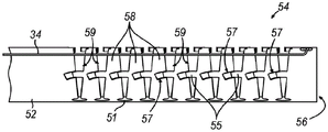
如图3A至图3B中最佳所见,柔性导轴部分(54)包括挠曲主体阵列(58),这些挠曲主体通过在刚性导轴部分(52)和开口远侧末端(56)之间延伸的弹性脊(51)彼此连接。弹性脊(51)朝向图3A所示的直的非关节运动位置偏置。根据本文的描述,弹性脊(51)足够灵活以允许挠曲主体(58)朝向和远离彼此移动,以便朝向和远离纵向轴线(LA)偏转开口远侧末端(56)。挠曲主体(58)包括互补互锁特征部(55,57),这些互补互锁特征部被构造成与相邻挠曲主体(58)互锁以防止挠曲主体(58)和弹性脊(51)在除预定关节运动路径之外的任何其他方向上弯曲、偏转、挠曲等。换句话说,互补互锁特征部(55,57)可帮助促进柔性导轴部分(54)的刚性同时在示例性使用期间处于期望的关节运动位置,同时还允许柔性导轴部分(54)在操作者利用关节运动驱动组件(30)时沿着预定路径朝向和远离纵向轴线(LA)挠曲(如图3A至图3B之间例示的)。As best seen in Figures 3A-3B, the flexible guide shaft portion (54) includes an array of flexure bodies (58) that pass between the rigid guide shaft portion (52) and the open distal tip (56) The elastic ridges (51) extending between them are connected to each other. The elastic ridges (51) are biased towards the straight non-articulating position shown in Figure 3A. According to the description herein, the elastic ridges (51) are flexible enough to allow the flexure bodies (58) to move toward and away from each other to deflect the open distal tip (56) toward and away from the longitudinal axis (LA). The flexure body (58) includes complementary interlocking features (55, 57) configured to interlock with the adjacent flexure body (58) to prevent the flexure body (58) and the resilient ridges ( 51) Bend, deflect, flex, etc. in any other direction than the predetermined articulation path. In other words, the complementary interlocking features (55, 57) may help promote rigidity of the flexible guide shaft portion (54) while being in the desired articulation position during exemplary use, while also allowing the flexible guide shaft portion (54) to be in the desired articulation position. The operator flexes toward and away from the longitudinal axis (LA) along a predetermined path as the operator articulates the drive assembly (30) (as illustrated between Figures 3A-3B).
如图3A中最佳所见,当柔性导轴部分(54)处于非关节运动构型(或各种关节运动构型)时,相邻挠曲主体(58)限定相应的间隙(59)以适应主体(58)的进一步挠曲。间隙(59)可以从柔性导轴部分(54)的外部部分延伸进入由柔性导轴部分(54)限定的内部管腔。随着挠曲主体(58)朝向和远离彼此移动以使开口远侧末端(56)进行关节运动,间隙(59)的大小改变。在一些情况下,如图3B中最佳所示,柔性导轴部分(54)可使开口远侧末端(56)进行关节运动至间隙(59)不再存在的位置。As best seen in Figure 3A, when the flexible guide shaft portion (54) is in a non-articulating configuration (or various articulating configurations), adjacent flexure bodies (58) define respective gaps (59) to Further deflection of the body (58) is accommodated. A gap (59) may extend from an outer portion of the flexible guide shaft portion (54) into an interior lumen defined by the flexible guide shaft portion (54). The size of the gap (59) changes as the flexure bodies (58) move toward and away from each other to articulate the open distal tip (56). In some cases, as best shown in Figure 3B, the flexible guide shaft portion (54) may articulate the open distal tip (56) to a position where the gap (59) no longer exists.
刚性导轴部分(52)与旋转驱动组件(40)的指轮(42)联接。仅举例来说,刚性导轴部分(52)和指轮(42)可以通过互补锥齿轮联接在一起。此类联接可根据2019年1月17日公布的名称为“Adjustable Instrument for Dilation of Anatomical Passageway”的美国专利公开第2019/0015645号的教导内容中的至少一些教导内容来提供,该公开的公开内容以引用方式并入本文。根据本文的教导内容,刚性导轴部分(52)和指轮(42)可以联接在一起的其他合适的方式对于本领域的技术人员而言将是显而易见的。Rigid guide shaft portion (52) is coupled to thumbwheel (42) of rotary drive assembly (40). For example only, the rigid guide shaft portion (52) and thumbwheel (42) may be coupled together by complementary bevel gears. Such linkages may be provided in accordance with at least some of the teachings of US Patent Publication No. 2019/0015645, entitled "Adjustable Instrument for Dilation of Anatomical Passageway," published on January 17, 2019, the disclosure of which Incorporated herein by reference. Other suitable ways in which rigid guide shaft portion (52) and thumbwheel (42) may be coupled together will be apparent to those skilled in the art in view of the teachings herein.
旋转驱动组件(40)的指轮(42)能够操作以围绕第一轴线(A1)相对于主体部分(14)旋转,如箭头(2)所示。指轮(42)围绕第一轴线(A1)的旋转被构造成驱动导向导管组件(50)相对于柄部组件(12)围绕导向导管组件(50)的纵向轴线(LA)的旋转,如箭头(6)所示。因此,操作者可以使导向导管组件(50)围绕纵向轴线(LA)旋转,以便选择性地相对于柄部组件(12)定位开口远侧末端(56)。根据本文的教导内容,可用于提供导向导管组件(50)的旋转的其他合适特征对于本领域的技术人员而言将是显而易见的。另选地,器械(10)可以被构造成使得导向导管组件(50)不可相对于柄部组件(12)旋转。The thumbwheel (42) of the rotary drive assembly (40) is operable to rotate relative to the body portion (14) about a first axis (A1), as indicated by arrow (2). Rotation of thumbwheel (42) about first axis (A1) is configured to drive rotation of guide catheter assembly (50) relative to handle assembly (12) about the longitudinal axis (LA) of guide catheter assembly (50), as indicated by arrows (6). Accordingly, the operator can rotate guide catheter assembly (50) about longitudinal axis (LA) to selectively position open distal tip (56) relative to handle assembly (12). Other suitable features that may be used to provide rotation of guide catheter assembly (50) will be apparent to those skilled in the art in view of the teachings herein. Alternatively, instrument (10) may be configured such that guide catheter assembly (50) is non-rotatable relative to handle assembly (12).
作为又一个仅例示性示例,器械(10)可以被构造成使得关节运动驱动组件(30)的旋钮(32)能够操作以驱动导向导管组件(50)围绕导向导管组件(50)的纵向轴线(LA)相对于柄部组件(12)的旋转,而不是指轮(42)能够操作以驱动导向导管组件(50)的旋转;并且也不是旋钮(32)能够操作以驱动柔性导轴部分(54)的关节运动,如下所述。As yet another merely illustrative example, the instrument (10) may be configured such that the knob (32) of the articulation drive assembly (30) is operable to drive the guide catheter assembly (50) about the longitudinal axis ( LA) relative to the rotation of the handle assembly (12), not the thumbwheel (42) is operable to drive the rotation of the guide catheter assembly (50); nor is the knob (32) operable to drive the flexible guide shaft portion (54) ) joint motion, as described below.
关节运动驱动组件(30)被构造成选择性地驱动柔性导轴部分(54)相对于由导向导管组件(50)限定的纵向轴线(LA)的关节运动。关节运动驱动组件(30)能够操作以使柔性导轴部分(54)挠曲,由此远离刚性导轴部分(52)的纵向轴线(LA)偏转开口远侧末端(56),如图3A至图3B之间例示的。关节运动驱动组件(30)包括围绕刚性导轴部分(52)同轴设置的旋钮(32)和推拉缆线(34)(参见图3A至图3B)。旋钮(32)能够围绕刚性导轴部分(52)的纵向轴线(LA)相对于刚性导轴部分(52)和主体部分(14)旋转,如箭头(4)所示。推拉缆线(34)可以沿着与弹性脊(51)相对的柔性导轴部分(54)的一部分延伸。推拉缆线(34)可以与弹性脊(51)充分隔离开以便响应于推拉缆线(34)的平移来挠曲弹性脊(51)。推拉缆线(34)可以位于由柔性导轴部分(54)限定的内部管腔的外部或范围内。Articulation drive assembly (30) is configured to selectively drive articulation of flexible guide shaft portion (54) relative to a longitudinal axis (LA) defined by guide catheter assembly (50). The articulation drive assembly (30) is operable to flex the flexible guide shaft portion (54), thereby deflecting the open distal tip (56) away from the longitudinal axis (LA) of the rigid guide shaft portion (52), as shown in Figures 3A- Illustrated between Figure 3B. The articulation drive assembly (30) includes a knob (32) and a push-pull cable (34) disposed coaxially around a rigid guide shaft portion (52) (see Figures 3A-3B). Knob (32) is rotatable relative to rigid guide shaft portion (52) and body portion (14) about a longitudinal axis (LA) of rigid guide shaft portion (52), as indicated by arrow (4). The push-pull cable (34) may extend along a portion of the flexible guide shaft portion (54) opposite the elastic spine (51). The push-pull cable (34) may be sufficiently isolated from the elastic ridge (51) to flex the elastic ridge (51) in response to translation of the push-pull cable (34). The push-pull cable (34) may be located outside or within the interior lumen defined by the flexible guide shaft portion (54).
旋钮(32)通过推拉缆线(34)与柔性导轴部分(54)的开口远侧末端(56)联接,使得旋钮(32)围绕刚性导轴部分(52)的旋转引起推拉缆线(34)的平移,从而使开口远侧末端(56)偏转,如图3A至图3B之间例示的。具体地,操作者可以在第一旋转方向上旋转旋钮(32)以朝近侧致动推拉缆线(34),由此弯曲柔性导轴部分(54)使得开口远侧末端(56)从纵向轴线(LA)偏转。The knob (32) is coupled to the open distal tip (56) of the flexible guide shaft portion (54) by a push-pull cable (34) such that rotation of the knob (32) about the rigid guide shaft portion (52) causes the push-pull cable (34) ), thereby deflecting the open distal tip (56), as illustrated between Figures 3A-3B. Specifically, the operator can rotate the knob (32) in a first rotational direction to actuate the push-pull cable (34) proximally, thereby bending the flexible guide shaft portion (54) so that the open distal tip (56) is longitudinally removed from the Axis (LA) deflection.
如果操作者希望拉直柔性导轴部分(54),则操作者可以在相反的第二旋转方向上旋转旋钮(32)以朝远侧致动推拉缆线(34),从而允许柔性导轴部分(54)由于弹性脊(51)的弹性性质而朝向非关节运动构型弯曲。根据本文的教导内容,关节运动驱动组件(30)可以被构造成远离纵向轴线(LA)偏转开口远侧末端(56)至各种角度以便进入各种解剖通道,这对于本领域的技术人员而言将是显而易见的。If the operator wishes to straighten the flexible guide shaft portion (54), the operator can rotate the knob (32) in the opposite second rotational direction to actuate the push-pull cable (34) distally, thereby allowing the flexible guide shaft portion (54) flexes towards the non-articulating configuration due to the elastic properties of the elastic ridges (51). In accordance with the teachings herein, articulation drive assembly (30) may be configured to deflect open distal tip (56) away from longitudinal axis (LA) to various angles for access to various anatomical passages, as would be apparent to those skilled in the art words will be obvious.
仅以另一个示例的方式,关节运动驱动组件(30)和柔性导轴部分(54)可根据以下美国专利公开的教导内容中的至少一些教导内容来构造和操作:2019年1月17日公布的名称为“Adjustable Instrument for Dilation of Anatomical Passageway”的美国专利公开第2019/0015645号,其公开内容以引用方式并入本文;和/或2018年11月1日公布的名称为“Deflectable Guide for Medical Instrument”的美国专利公开第2018/0311472号,其公开内容以引用方式并入本文。By way of another example only, the articulation drive assembly (30) and the flexible guide shaft portion (54) may be constructed and operated in accordance with at least some of the teachings of the following US Patent Publication: Published Jan. 17, 2019 U.S. Patent Publication No. 2019/0015645 entitled "Adjustable Instrument for Dilation of Anatomical Passageway", the disclosure of which is incorporated herein by reference; and/or entitled "Deflectable Guide for Medical" published on November 1, 2018 Instrument" US Patent Publication No. 2018/0311472, the disclosure of which is incorporated herein by reference.
作为另一个仅例示性示例,器械(10)可以被构造成使得指轮(42)能够操作以驱动柔性导轴部分(54)的关节运动,而不是旋钮(32)能够操作以驱动导向导管组件(50)围绕导向导管组件(50)的纵向轴线(LA)相对于柄部组件(12)的旋转;并且也不是指轮(42)能够操作以驱动导向导管组件(50)围绕导向导管组件(50)的纵向轴线(LA)相对于柄部组件(12)的旋转。As another merely illustrative example, instrument (10) may be configured such that thumbwheel (42) is operable to drive articulation of flexible guide shaft portion (54), rather than knob (32) operable to drive guide catheter assembly (50) Rotation about the longitudinal axis (LA) of the guide catheter assembly (50) relative to the handle assembly (12); and neither is the thumbwheel (42) operable to drive the guide catheter assembly (50) around the guide catheter assembly ( Rotation of the longitudinal axis (LA) of 50) relative to the handle assembly (12).
B.示例性导丝组件和扩张导管组件B. Exemplary Guide Wire Assembly and Dilation Catheter Assembly
如上所述,导丝组件(60)和扩张导管组件(70)均可滑动地联接到柄部组件(12)和导向导管组件(50),使得导丝组件(60)和扩张导管组件(70)可以相对于导向导管组件(50)以及相对于彼此独立地致动。如将在下文更详细地描述的,导丝组件(60)和扩张导管组件(70)可与柄部组件(12)和导向导管组件(50)结合使用,以便进入和扩张期望的解剖通道。As described above, both guidewire assembly (60) and dilation catheter assembly (70) are slidably coupled to handle assembly (12) and guide catheter assembly (50) such that guidewire assembly (60) and dilation catheter assembly (70) ) can be actuated independently with respect to the guide catheter assembly (50) and with respect to each other. As will be described in more detail below, guidewire assembly (60) and dilation catheter assembly (70) may be used in conjunction with handle assembly (12) and guide catheter assembly (50) to access and dilate a desired anatomical passage.
如图2中最佳所见,导丝组件(60)包括导丝(62)和导丝移动机构(66)。在一些情况下,导丝(62)可以包括延伸到远侧照明末端和/或位置传感器中的光纤。仅以举例的方式,导丝(62)可根据以下专利的教导内容中的至少一些教导内容来构造:2015年10月13日公布的名称为“Sinus Illumination Lightwire Device”的美国专利9,155,492;2017年9月12日公布的名称为“Medical Guidewire with Integral Light Transmission”的美国专利9,757,018;和/或2020年4月7日公布的名称为“Navigation Guidewire with InterlockedCoils”的美国专利10,610,308,该些专利的公开内容以引用方式并入本文。As best seen in Figure 2, the guidewire assembly (60) includes a guidewire (62) and a guidewire moving mechanism (66). In some cases, guidewire (62) may include optical fibers that extend into the distal illumination tip and/or position sensor. By way of example only, guidewire (62) may be constructed in accordance with at least some of the teachings of: US Patent 9,155,492, "Sinus Illumination Lightwire Device," issued Oct. 13, 2015; 2017 U.S. Patent 9,757,018, "Medical Guidewire with Integral Light Transmission," issued September 12; and/or U.S. Patent 10,610,308, "Navigation Guidewire with Interlocked Coils," issued April 7, 2020, the disclosures of those patents The contents are incorporated herein by reference.
如上所述,导丝移动机构(66)通过第一轨道(24)可滑动地联接到柄部组件(12),使得导丝移动机构(66)可沿第一轨道(24)平移并穿过扩张导管移动机构(80)的腔体(82)。根据本文的描述,导丝(62)可以选择性地联接到导丝移动机构(66),使得导丝移动机构(66)相对于柄部组件(12)的平移驱动导丝(62)的平移。导丝移动机构(66)包括平移托架(68)以及导丝锁定和旋转旋钮(67)。平移托架(68)通过第一轨道(24)可滑动地联接到柄部组件(12),而导丝锁定和旋转旋钮(67)可旋转地设置在平移托架(68)上。具体地,导丝锁定和旋转旋钮(67)可以围绕其纵向轴线相对于平移托架(68)旋转;而旋钮(67)也可以与托架(68)一起相对于柄部组件(12)平移。As noted above, the guidewire movement mechanism (66) is slidably coupled to the handle assembly (12) by the first track (24) such that the guidewire movement mechanism (66) can translate along the first track (24) and through The cavity (82) of the catheter moving mechanism (80) is dilated. In accordance with the description herein, guidewire (62) may be selectively coupled to guidewire movement mechanism (66) such that translation of guidewire movement mechanism (66) drives translation of guidewire (62) relative to translation of handle assembly (12). . The guide wire moving mechanism (66) includes a translation bracket (68) and a guide wire locking and rotation knob (67). A translation bracket (68) is slidably coupled to the handle assembly (12) by the first track (24), and a guidewire locking and rotation knob (67) is rotatably disposed on the translation bracket (68). Specifically, the guidewire locking and rotation knob (67) is rotatable about its longitudinal axis relative to the translating bracket (68); and the knob (67) can also be translated with the bracket (68) relative to the handle assembly (12) .
导丝锁定和旋转旋钮(67)可操作地联接到导丝(62),使得旋钮(67)围绕其自身的纵向轴线的旋转驱动导丝(62)围绕其自身的纵向轴线的旋转;并且还使得旋钮(67)相对于柄部组件(12)的平移驱动导丝(62)的平移。旋钮(67)固定到导丝(62)上,使得旋钮(67)和导丝(62)一体地旋转。因此,如果操作者相对于平移托架(68)在第一旋转方向上旋转旋钮(67),则导丝(62)的直接联接到旋钮(67)的部分围绕其对应的纵向轴线在第一旋转方向上旋转,而导丝(62)设置在导丝管腔(85)内的部分也围绕其对应的纵向轴线在第一旋转方向上旋转,并且导丝(62)的远侧端部(64)也围绕其对应的纵向轴线在第一旋转方向上旋转。旋钮(67)可以被构造成用于将导丝(62)牢固地锁定到导丝移动机构(66)并解锁,使得导丝(62)相对于扩张导管(72)的纵向放置可以重新定位,或使得新导丝(62)可用于更换先前使用的导丝(62)。a guidewire locking and rotation knob (67) is operably coupled to the guidewire (62) such that rotation of the knob (67) about its own longitudinal axis drives rotation of the guidewire (62) about its own longitudinal axis; and also Translation of the knob (67) relative to the handle assembly (12) is caused to drive translation of the guidewire (62). The knob (67) is fixed to the guide wire (62) so that the knob (67) and the guide wire (62) rotate integrally. Thus, if the operator rotates the knob (67) in the first rotational direction relative to the translation bracket (68), the portion of the guide wire (62) that is directly coupled to the knob (67) is in the first rotational direction about its corresponding longitudinal axis while the portion of the guide wire (62) disposed within the guide wire lumen (85) also rotates in the first rotational direction about its corresponding longitudinal axis, and the distal end of the guide wire (62) ( 64) also rotate in a first rotational direction about its corresponding longitudinal axis. Knob (67) may be configured for securely locking and unlocking guidewire (62) to guidewire moving mechanism (66) so that longitudinal placement of guidewire (62) relative to dilation catheter (72) can be repositioned, Or make a new guide wire (62) available to replace a previously used guide wire (62).
如图1至图2中最佳所见,导丝(62)从导丝移动机构(66)朝远侧延伸的部分延伸到刮削槽(74)和扩张导管(72)的导丝管腔(85)中。导丝(62)可滑动地设置在导丝管腔(85)内,使得导丝(62)可相对于扩张导管(72)、柄部组件(12)和导向导管组件(50)平移。因此,导丝(62)的远侧端部(64)可以朝远侧和近侧平移穿过扩张导管(72)的开口远侧端部(76)。在一些型式中,导丝(62)的远侧部分比导丝(62)的近侧端部更具柔性。在一些型式中,导丝(62)的远侧端部(64)可以被构造成照明,因为此类照明可提供通过患者的面部的经皮照明以使得操作者能够相对容易地可视地确认导丝(62)的远侧端部(64)的定位。根据本文的教导内容,向导丝(62)的远侧端部(64)提供照明的各种结构和方法对于本领域的技术人员而言将是显而易见的。As best seen in Figures 1-2, the guidewire (62) extends from the distally extending portion of the guidewire movement mechanism (66) to the scraping slot (74) and the guidewire lumen (72) of the dilation catheter (72). 85) in. Guidewire (62) is slidably disposed within guidewire lumen (85) such that guidewire (62) can translate relative to dilation catheter (72), handle assembly (12) and guide catheter assembly (50). Thus, the distal end (64) of the guide wire (62) can be translated distally and proximally through the open distal end (76) of the dilation catheter (72). In some versions, the distal portion of guidewire (62) is more flexible than the proximal end of guidewire (62). In some versions, the distal end (64) of the guide wire (62) may be configured to illuminate, as such illumination may provide percutaneous illumination through the patient's face to enable the operator to visually confirm with relative ease Positioning of the distal end (64) of the guide wire (62). Various structures and methods of providing illumination to the distal end (64) of the guide wire (62) will be apparent to those skilled in the art in view of the teachings herein.
根据本文的描述,刮削槽(74)沿扩张导管(72)延伸合适的距离,使得导丝(62)的在导丝移动机构(66)和导丝管腔(85)之间延伸的部分可以在导丝(62)的示例性平移期间平移,而不被扩张导管(72)防止。换句话说,刮削槽(74)的尺寸被设计为在根据本文的描述的示例性使用期间适应导丝组件(60)相对于扩张导管(72)的平移。导丝(62)具有使得导丝(62)的远侧端部(64)能够适当地定位在扩张导管(72)的开口远侧端部(76)的远侧,同时导丝(62)的近侧部分适当地联接到导丝移动机构(66)的长度。According to the description herein, the scraping slot (74) extends a suitable distance along the dilation catheter (72) such that the portion of the guidewire (62) extending between the guidewire movement mechanism (66) and the guidewire lumen (85) can be Translation during exemplary translation of guidewire (62) is not prevented by dilation catheter (72). In other words, scraping slot (74) is dimensioned to accommodate translation of guidewire assembly (60) relative to dilation catheter (72) during exemplary use in accordance with the description herein. The guide wire (62) has a distal end (64) of the guide wire (62) that can be properly positioned distal to the open distal end (76) of the dilation catheter (72), while the The proximal portion is suitably coupled to the length of the guide wire moving mechanism (66).
如图2中最佳所见,扩张导管组件(70)包括扩张导管(72)、可充胀球囊(78)和限定腔体(82)的扩张导管移动机构(80)。如上所述,扩张导管移动机构(80)通过第二轨道(26)可滑动地设置在柄部组件(12)上,而扩张导管(72)的一部分可滑动地设置在柄部组件(12)的限定第一轨道(24)的部分内。As best seen in Figure 2, dilation catheter assembly (70) includes a dilation catheter (72), an inflatable balloon (78), and a dilation catheter movement mechanism (80) defining a lumen (82). As described above, the dilation catheter moving mechanism (80) is slidably disposed on the handle assembly (12) via the second rail (26), and a portion of the dilation catheter (72) is slidably disposed on the handle assembly (12) within the portion that defines the first track (24).
扩张导管(72)与扩张导管移动机构(80)联接,使得扩张导管移动机构(80)的平移驱动扩张导管(72)相对于柄部组件(12)、扩张导管组件(70)和导丝组件(60)的平移。另外,扩张导管(72)的一部分可滑动地设置在导向导管组件(50)内。导丝(62)和扩张导管(72)均具有合适的长度,以使得导丝(62)的远侧端部(64)和扩张导管组件(70)的可充胀球囊(78)能够朝远侧平移超过导向导管组件(50)的开口远侧末端(56),而导丝(62)和扩张导管(72)的近侧部分分别适当地联接到导丝移动机构(66)和扩张导管移动机构(80)。扩张导管(72)的远侧部分和/或可充胀球囊(78)可以适当地为柔性,以便在滑动通过柔性导轴部分(54)时在挠曲位置弯曲。The dilation catheter (72) is coupled to the dilation catheter movement mechanism (80) such that translation of the dilation catheter movement mechanism (80) drives the dilation catheter (72) relative to the handle assembly (12), the dilation catheter assembly (70) and the guide wire assembly (60) translation. Additionally, a portion of dilation catheter (72) is slidably disposed within guide catheter assembly (50). Both the guide wire (62) and the dilation catheter (72) are of suitable lengths to allow the distal end (64) of the guide wire (62) and the inflatable balloon (78) of the dilation catheter assembly (70) to be directed toward the dilation catheter assembly (70). Distal translation beyond the open distal tip (56) of the guide catheter assembly (50) while the proximal portions of the guide wire (62) and dilation catheter (72) are appropriately coupled to the guide wire movement mechanism (66) and dilation catheter, respectively Movement mechanism (80). The distal portion of the dilation catheter (72) and/or the inflatable balloon (78) may be suitably flexible so as to bend in a flexed position when sliding through the flexible guide shaft portion (54).
可充胀球囊(78)位于扩张导管(72)的远侧部分处。扩张导管(72)限定导丝管腔(未示出)、充胀管腔(未示出)和冲洗管腔(未示出)。导丝管腔(未示出)朝近侧延伸以与刮削槽(74)连通,使得导丝(62)可以通过刮削槽(74)从导丝移动机构(66)进入导丝管腔(未示出)。另外,导丝管腔(未示出)一直延伸到扩张导管(72)的开口远侧端部(76),使得导丝(62)的远侧端部(64)可以朝远侧平移超过扩张导管(72)的开口远侧端部(76)。充胀管腔(未示出)可以与导丝管腔(未示出)和冲洗管腔(未示出)两者流体隔离。充胀管腔(未示出)在可充胀球囊(78)内朝远端终止。扩张导管(72)的近侧端部包括与充胀管腔(未示出)流体连通的第一端口(未示出)和与冲洗管腔(未示出)流体连通的第二端口(未示出)。An inflatable balloon (78) is located at the distal portion of the dilation catheter (72). Dilation catheter (72) defines a guidewire lumen (not shown), an inflation lumen (not shown) and an irrigation lumen (not shown). The guidewire lumen (not shown) extends proximally to communicate with the scraping slot (74) so that the guidewire (62) can pass through the scraping slot (74) from the guidewire moving mechanism (66) into the guidewire lumen (not shown). Shows). Additionally, a guidewire lumen (not shown) extends all the way to the open distal end (76) of the dilation catheter (72) so that the distal end (64) of the guidewire (62) can translate distally beyond the dilation Open distal end (76) of catheter (72). The inflation lumen (not shown) may be fluidly isolated from both the guidewire lumen (not shown) and the irrigation lumen (not shown). An inflation lumen (not shown) terminates distally within the inflatable balloon (78). The proximal end of dilation catheter (72) includes a first port (not shown) in fluid communication with an inflation lumen (not shown) and a second port (not shown) in fluid communication with an irrigation lumen (not shown). Shows).
第一端口(未示出)可以与被构造成将足够量的流体传送到可充胀球囊(78)并从可充胀球囊传送的充胀装置联接,使得可充胀球囊(78)可在放气状态(如图5C所示)与充胀状态(如图5D所示)之间转变。根据本文的教导内容,可使用任何合适的充胀装置,这对于本领域的技术人员而言将是显而易见的。A first port (not shown) may be coupled with an inflation device configured to deliver a sufficient amount of fluid to and from the inflatable balloon (78) such that the inflatable balloon (78) ) can transition between a deflated state (shown in Figure 5C) and an inflated state (shown in Figure 5D). Any suitable inflation device may be used, as will be apparent to those skilled in the art in light of the teachings herein.
冲洗管腔(未示出)可以沿着扩张导管(72)朝远侧与导丝管腔(未示出)会聚,使得冲洗管腔(未示出)和导丝管腔(未示出)在会聚点和其远侧处彼此流体连通。第二端口(未示出)可以与冲洗装置联接,该冲洗装置被构造成将冲洗流体传送通过冲洗管腔(未示出)并从扩张导管(72)的开口远侧端部(76)流出。扩张导管(72)的从可充胀球囊(78)朝远侧延伸的部分可具有用于排出冲洗流体的一个或多个圆周开口。The irrigation lumen (not shown) may converge distally along the dilation catheter (72) with the guidewire lumen (not shown) such that the irrigation lumen (not shown) and the guidewire lumen (not shown) In fluid communication with each other at the point of convergence and its distal side. A second port (not shown) may be coupled with an irrigation device configured to deliver irrigation fluid through an irrigation lumen (not shown) and out of the open distal end (76) of the dilation catheter (72) . The portion of dilation catheter (72) extending distally from inflatable balloon (78) may have one or more circumferential openings for draining irrigation fluid.
根据本文的教导内容,在当前示例中,扩张导管(72)和可充胀球囊(78)用作工作元件,可以使用限定导丝管腔的任何其他合适的导管,这对于本领域的技术人员而言将是显而易见的。In the current example, dilation catheter (72) and inflatable balloon (78) are used as working elements in accordance with the teachings herein, any other suitable catheter that defines a guidewire lumen may be used, which is not amenable to those skilled in the art personnel will be obvious.
C.使用器械扩张解剖通道的示例性操作C. Exemplary Procedure for Dilating Anatomical Channels Using Instruments
图4A至图5D示出了用于进入和扩张目标解剖通道(诸如窦口(O))的示例性程序。虽然柔性导轴部分(54)在图5A至图5D中以笔直构型示出,在实际使用中柔性导轴部分(54)可以挠曲或弯曲以实现弯曲角度,该弯曲角度有助于进入目标解剖通道(例如,上颌窦口、蝶窦口、额隐窝、咽鼓管等)。柔性导轴部分(54)可在导向导管组件(50)已经被插入患者体内之前和/或在导向导管组件(50)已经被插入患者体内之后挠曲或弯曲。首先,如图5A中最佳所示,导向导管组件(50)的开口远侧末端(56)可以首先定位在目标解剖通道(诸如该示例中的窦口(O))附近。可在由内窥镜提供的可视化下执行导向导管组件(50)的开口远侧末端(56)的定位。4A-5D illustrate exemplary procedures for accessing and dilating a target anatomical passage, such as an ostium (O). Although the flexible guide shaft portion ( 54 ) is shown in a straight configuration in FIGS. 5A-5D , in actual use the flexible guide shaft portion ( 54 ) can flex or bend to achieve a bending angle that facilitates access Target anatomical passages (eg, maxillary ostium, sphenoid ostium, frontal recess, Eustachian tube, etc.). The flexible guide shaft portion (54) may flex or bend before the guide catheter assembly (50) has been inserted into the patient and/or after the guide catheter assembly (50) has been inserted into the patient. First, as best shown in Figure 5A, the open distal tip (56) of the guide catheter assembly (50) may first be positioned near the target anatomical passage, such as the ostium (O) in this example. The positioning of the open distal tip (56) of the guide catheter assembly (50) can be performed under visualization provided by the endoscope.
在此阶段,导丝(62)的远侧端部(64)以及扩张导管组件(70)的可充胀球囊(78)和开口远侧端部(76)在该阶段可以定位在导向导管组件(50)的柔性导轴部分(54)内或其近侧。图6A示出了相对于柄部组件(12)位于对应的近侧位置的导丝移动机构(66)和扩张导管移动机构(80),其中此类近侧位置与定位在导向导管组件(50)的柔性导轴部件(54)内或近侧的远侧端部(64)和开口远侧端部(76)相关联。At this stage, the distal end (64) of the guide wire (62) as well as the inflatable balloon (78) and open distal end (76) of the dilation catheter assembly (70) can be positioned at the guide catheter at this stage within or proximal to the flexible guide shaft portion (54) of the assembly (50). Figure 6A shows the guidewire movement mechanism (66) and dilation catheter movement mechanism (80) in corresponding proximal positions relative to the handle assembly (12), wherein such proximal positions are the same as those positioned at the guide catheter assembly (50). A distal end (64) within or proximal of the flexible guide shaft member (54) of ) is associated with an open distal end (76).
在导向导管组件(50)已经定位之后,操作者可以将导丝移动机构(66)从图4A所示的近侧位置推进至图4B所示的远侧位置。导丝移动机构(66)的远侧移动朝远侧驱动导丝(62)通过导向导管组件(50)的开口远侧末端(56),使得导丝(62)的远侧端部(64)穿过窦口(O)(或一些其他目标解剖通道),如图5B所示。在导丝(62)的远侧端部(64)被构造成照明的实例中,操作者可以照明远侧端部(64),该照明可提供通过患者的面部的经皮照明以使得操作者能够相对容易地可视地确认导丝(62)的远侧端部(64)的定位。After guide catheter assembly (50) has been positioned, the operator may advance guidewire movement mechanism (66) from the proximal position shown in Figure 4A to the distal position shown in Figure 4B. Distal movement of the guidewire movement mechanism (66) drives the guidewire (62) distally through the open distal tip (56) of the guide catheter assembly (50) such that the distal end (64) of the guidewire (62) Pass through the sinus ostium (O) (or some other target anatomical passage) as shown in Figure 5B. In instances where the distal end (64) of the guide wire (62) is configured to illuminate, the operator may illuminate the distal end (64), which may provide percutaneous illumination through the patient's face to allow the operator to illuminate The positioning of the distal end (64) of the guide wire (62) can be visually confirmed relatively easily.
通过导向导管组件(50)的开口远侧末端(56)和如图5B所示合适地定位的导丝(62),操作者可以将扩张导管移动机构(80)从图4B所示的近侧位置推进到图4C中所示的远侧位置。扩张导管移动机构(80)的远侧移动沿着导丝(62)驱动可充胀球囊(78)并通过导向导管组件(50)的开口远侧末端(56),同时可充胀球囊(78)处于放气状态,使得可充胀球囊(78)通过窦口(O)(或一些其他目标解剖通道)定位,如图5C所示。With the open distal tip (56) of the guide catheter assembly (50) and the guide wire (62) appropriately positioned as shown in Figure 5B, the operator can move the dilation catheter movement mechanism (80) from the proximal end shown in Figure 4B The position is advanced to the distal position shown in Figure 4C. Distal movement of the dilation catheter movement mechanism (80) drives the inflatable balloon (78) along the guide wire (62) and through the open distal tip (56) of the guide catheter assembly (50) while the inflatable balloon is inflated (78) is in a deflated state such that the inflatable balloon (78) is positioned through the sinus ostium (O) (or some other target anatomical passage), as shown in Figure 5C.
在可充胀球囊(78)已经定位在口(O)内之后,可如图5D所示使可充胀球囊(78)充胀,从而使口(O)扩张。根据本文的教导内容,球囊(78)可利用任何合适的技术来充胀,这对于本领域的技术人员而言将是显而易见的。仅以举例的方式,可将可充胀球囊(78)充胀到约10个大气压到约12个大气压的压力。可充胀球囊(78)可保持在该体积下持续几秒以充分打开口(O)(或其他目标解剖通道)。根据本文的教导内容,可充胀球囊(78)然后可利用任何合适的技术恢复到放气状态,这对于本领域的技术人员而言将是显而易见的。可充胀球囊(78)可在不同口和/或其他目标解剖通道中重复地充胀和放气。After the inflatable balloon (78) has been positioned within the port (O), the inflatable balloon (78) may be inflated as shown in Figure 5D, thereby expanding the port (O). Balloon (78) may be inflated using any suitable technique, as will be apparent to those skilled in the art in light of the teachings herein. By way of example only, the inflatable balloon (78) may be inflated to a pressure of about 10 atmospheres to about 12 atmospheres. The inflatable balloon (78) can be held at this volume for several seconds to fully open the port (O) (or other target anatomical passage). The inflatable balloon (78) may then be returned to a deflated state using any suitable technique, as will be apparent to those skilled in the art in light of the teachings herein. The inflatable balloon (78) can be repeatedly inflated and deflated in different ports and/or other target anatomical passages.
此后,导丝移动机构(66)和扩张导管移动机构(80)可以移动回其相应的近侧位置,从而使导丝(62)和扩张导管(72)朝近侧平移回到导向导管组件(50)中。导向导管组件(50)然后可以从患者体内移除。Thereafter, the guidewire movement mechanism (66) and dilation catheter movement mechanism (80) can be moved back to their respective proximal positions, thereby translating the guidewire (62) and dilation catheter (72) proximally back to the guide catheter assembly ( 50) in. Guide catheter assembly (50) can then be removed from the patient.
应当理解,可以在程序的任何合适部分期间提供冲洗和/或抽吸。根据本文的教导内容,可以根据本文的描述或利用其他合适的方法和/或装置提供冲洗和/或抽吸,这对于本领域的技术人员而言将是显而易见的。扩张导管组件(70)、导丝组件(60)和导向导管组件(50)可以从患者体内移除。It will be appreciated that irrigation and/or suction may be provided during any suitable portion of the procedure. Irrigation and/or suction may be provided in light of the teachings herein, or using other suitable methods and/or devices, as will be apparent to those skilled in the art. Dilation catheter assembly (70), guide wire assembly (60) and guide catheter assembly (50) are removable from the patient.
II.具有部分套筒的示例性柔性导轴部分II. Exemplary Flexible Guide Shaft Section with Partial Sleeve
如上所述,流体管腔(15)通过由主体部分(14)限定的内部通道(未示出)与导向导管组件(50)的内部管腔流体连通,使得抽吸/冲洗源(17)(参见图1)可在示例性使用期间在导向导管组件(50)的开口远侧末端(56)处提供抽吸/冲洗。然而,如上所述,柔性导轴部分(54)的相邻挠曲主体(58)限定相应的间隙(59)以适应主体(58)的进一步挠曲。As described above, the fluid lumen (15) is in fluid communication with the interior lumen of the guide catheter assembly (50) through an interior passage (not shown) defined by the body portion (14) such that the suction/irrigation source (17) ( See Figure 1) Suction/irrigation may be provided at the open distal tip (56) of the guide catheter assembly (50) during exemplary use. However, as discussed above, the adjacent flexure bodies (58) of the flexible guide shaft portion (54) define corresponding gaps (59) to accommodate further deflection of the body (58).
间隙(59)可以提供内部管腔与柔性导轴部分(54)的外部之间的流体连通,使得旨在与开口远侧末端(56)连通的流体/抽吸可能过早地通过间隙(59)漏出而不是适当地到达开口远侧末端(56)。因此,根据本文的描述,在一些情况下,可能期望提供至少部分地覆盖间隙(59)的套筒以试图防止流体/抽吸通过间隙(59)漏出,从而允许预期的流体/抽吸适当地通过开口远侧末端(56)而不是间隙(59),同时还适应柔性导轴部分(54)的挠曲。The gap (59) may provide fluid communication between the inner lumen and the exterior of the flexible guide shaft portion (54) so that fluid/suction intended to communicate with the open distal tip (56) may prematurely pass through the gap (59) ) leaks out without properly reaching the open distal tip (56). Thus, in light of the descriptions herein, in some cases it may be desirable to provide a sleeve at least partially covering the gap (59) in an attempt to prevent fluid/suction from leaking through the gap (59), thereby allowing the intended fluid/suction to properly Through the open distal tip (56) instead of the gap (59), while also accommodating deflection of the flexible guide shaft portion (54).
另外,如上所述,扩张导管组件(70)的可充胀球囊(78)和开口远侧端部(76)可以定位在导向导管组件(50)的柔性导轴部分(54)内或其附近,使得可充胀球囊(78)可在柔性导轴部分(54)内平移。根据本文的描述,同样如上所述,当挠曲主体(58)朝向和远离彼此移动以使开口远侧末端(56)进行关节运动时,间隙(59)的大小改变,并且在一些情况下,间隙(59)实际上是闭合的。Additionally, as described above, the inflatable balloon (78) and open distal end (76) of the dilation catheter assembly (70) may be positioned within the flexible guide shaft portion (54) of the guide catheter assembly (50) or its adjacent so that the inflatable balloon (78) can translate within the flexible guide shaft portion (54). In accordance with the description herein, and also as described above, as the flexure bodies (58) move toward and away from each other to articulate the open distal tip (56), the size of the gap (59) changes, and in some cases, The gap (59) is practically closed.
在一些情况下,可充胀球囊(78)在可充胀球囊(78)在内部管腔内前进和/或回缩期间可能倾向于钩住或以其他方式不期望地接触柔性主体(58)的限定间隙(59)的部分。根据本文的描述,如果可充胀球囊(78)(或任何其他合适的装置)容纳在柔性导轴部分(54)内而柔性主体(58)朝向彼此移动以使开口远侧末端(56)进行关节运动,则柔性主体(58)的限定间隙(59)的部分可能不期望地捕获和/或夹紧可充胀球囊(78)(或任何其他合适的装置),这继而可能损坏可充胀球囊(78)(或任何其他合适的装置)。因此,在一些情况下,可能期望提供一种套筒,当开口远侧末端(56)进行关节运动时或当可充胀球囊(78)在由柔性导轴部分(54)限定的内部管腔内平移时,该套筒至少部分地保护可充胀球囊(78)(或任何其他合适的装置)免受挠曲主体(58)的夹紧、捕获或损坏。In some cases, the inflatable balloon (78) may tend to snag or otherwise undesirably contact the flexible body ( 58) that defines the gap (59). According to the description herein, if the inflatable balloon (78) (or any other suitable device) is received within the flexible guide shaft portion (54) and the flexible bodies (58) are moved toward each other to allow the open distal tip (56) Articulation, the portion of the flexible body (58) that defines the gap (59) may undesirably capture and/or pinch the inflatable balloon (78) (or any other suitable device), which in turn may damage the Inflate balloon (78) (or any other suitable device). Therefore, in some cases it may be desirable to provide a sleeve when articulating the open distal tip (56) or when the inflatable balloon (78) is in the inner tube defined by the flexible guide shaft portion (54). During intraluminal translation, the sleeve at least partially protects the inflatable balloon (78) (or any other suitable device) from pinching, entrapment or damage by the flexure body (58).
图6至图8示出了可代替上文所述的导向导管组件(50)容易地结合到器械(10)中的另选导向导管组件(150)。导向导管组件(150)可基本上类似于上述导向导管组件(50),其不同之处将于下文详述。类似于导向导管组件(50),导向导管组件(150)包括基本上类似于上述刚性导轴部分(52)和柔性导轴部分(54)的刚性导轴部分(152)和柔性导轴部分(154)。刚性导轴部分(152)可以与柄部组件(12)的旋转驱动组件(40)操作地联接,使得旋转驱动组件(40)可以围绕纵向轴线(LA)旋转导向导管组件(150)。另外,根据本文的描述,柔性导轴部分(154)可以操作地联接到柄部组件(12)的关节运动驱动组件(30),使得关节运动驱动组件(30)可挠曲柔性导轴部分(154)。Figures 6-8 illustrate an alternative guide catheter assembly (150) that can be easily incorporated into the instrument (10) in place of the guide catheter assembly (50) described above. Guide catheter assembly (150) may be substantially similar to guide catheter assembly (50) described above, with the differences described in detail below. Similar to guide catheter assembly (50), guide catheter assembly (150) includes rigid guide shaft portion (152) and flexible guide shaft portion (152) and flexible guide shaft portion ( 154). Rigid guide shaft portion ( 152 ) may be operatively coupled with rotational drive assembly ( 40 ) of handle assembly ( 12 ) such that rotational drive assembly ( 40 ) can rotate guide catheter assembly ( 150 ) about longitudinal axis (LA). Additionally, in accordance with the description herein, the flexible guide shaft portion (154) may be operatively coupled to the articulation drive assembly (30) of the handle assembly (12) such that the articulation drive assembly (30) can flex the flexible guide shaft portion ( 154).
柔性导轴部分(154)包括纵向延伸的弹性脊(151)和具有互补互锁特征部(155,157)的线性挠曲主体阵列(158),它们基本上类似于上述弹性脊(51)、挠曲主体(58)和互补互锁特征部(155,157),其不同之处将于下文详述。因此,挠曲主体(158)限定多个间隙(159),这些间隙基本上类似于上述间隙(59)。如图7中最佳所见,弹性脊(151)和挠曲主体(158)限定内部管腔(162),该内部管腔与刚性导轴部分(152)的内部管腔和开口远侧末端(156)连通。在当前示例中,柔性导轴部分(154)包括限定开口远侧末端(156)的末端主体(160)。末端主体(160)与最远侧柔性主体(158)联接。The flexible guide shaft portion (154) includes a longitudinally extending resilient ridge (151) and an array (158) of linear flexure bodies with complementary interlocking features (155, 157) substantially similar to the resilient ridges (51), flexures described above. Main body (58) and complementary interlocking features (155, 157), the differences of which will be described in detail below. Thus, the flexure body (158) defines a plurality of gaps (159) which are substantially similar to the gaps (59) described above. As best seen in Figure 7, the elastic spine (151) and the flexure body (158) define an inner lumen (162) that is connected to the inner lumen and open distal tip of the rigid guide shaft portion (152) (156) Connected. In the current example, flexible guide shaft portion (154) includes a tip body (160) defining an open distal tip (156). A tip body (160) is coupled with the distal-most flexible body (158).
最远侧挠曲主体(158)限定至少一个联接特征部(164),该联接特征部在组装时可与关节运动驱动组件(30)的推拉缆线(34)联接。如图9中最佳所示,推拉缆线(34)可以沿着挠曲主体(158)的内部部分延伸以便与联接特征部(164)联接。根据本文的教导内容,推拉缆线(34)可以利用任何其他合适的方式焊接、激光焊接或联接到联接特征部(164),这对于本领域的技术人员而言将是显而易见的。如图8中最佳所见,弹性脊(151)限定多个挠曲切口(153),挠曲主体(158)从这些挠曲切口延伸。挠曲切口(153)可促进主体(158)在开口远侧末端(156)的关节运动期间的挠曲。The distal-most flexure body (158) defines at least one coupling feature (164) that, when assembled, can be coupled with the push-pull cable (34) of the articulation drive assembly (30). As best shown in FIG. 9, the push-pull cable (34) may extend along the inner portion of the flexure body (158) for coupling with the coupling feature (164). Push-pull cable (34) may be welded, laser welded, or coupled to coupling feature (164) using any other suitable means, as will be apparent to those skilled in the art in light of the teachings herein. As best seen in Figure 8, the elastic ridges (151) define a plurality of flexure notches (153) from which the flexure bodies (158) extend. Flexure cutout (153) may facilitate flexure of body (158) during articulation of open distal tip (156).
如图7中最佳所见,柔性导轴部分(154)还包括外部套筒或衬里(170)和部分内部套筒或衬里(180)。如下文将更详细地描述的,外部套筒(170)围绕弹性脊(151)的外部和限定间隙(159)的线性挠曲主体阵列(158)设置,以防止流体通过间隙(159)逸出,从而促进抽吸/冲洗源(17)和开口远侧末端(156)之间的合适流体连通。另外,如将在下文更详细地描述的,部分内部套筒(180)设置在弹性脊(151)的内部和限定间隙(159)的挠曲主体阵列(158)内,以便保护可滑动地设置在由弹性脊(151)和柔性主体(158)限定的内部管腔(162)内的工作元件,以及促进抽吸/冲洗源(17)和开口远侧末端(156)之间的合适流体连通。As best seen in Figure 7, the flexible guide shaft portion (154) also includes an outer sleeve or liner (170) and a portion of an inner sleeve or liner (180). As will be described in more detail below, an outer sleeve (170) is provided around the exterior of the elastic ridges (151) and an array of linear flexure bodies (158) defining gaps (159) to prevent fluid from escaping through the gaps (159) , thereby facilitating proper fluid communication between the suction/irrigation source (17) and the open distal tip (156). Additionally, as will be described in greater detail below, a portion of the inner sleeve (180) is disposed within the interior of the resilient spine (151) and within the array of flexure bodies (158) defining gaps (159) so as to protect the slidably disposed Working element within inner lumen (162) defined by elastic spine (151) and flexible body (158), and facilitating proper fluid communication between suction/irrigation source (17) and open distal tip (156) .
外部套筒(170)从刚性导轴部分(152)的内部部分一直延伸到末端主体(160)。外部套筒(170)包括内表面(174)和外表面(176)。内表面(174)限定通道(172),该通道的尺寸被设计为容纳弹性脊(151)和挠曲主体(158)。在当前示例中,外部套筒(170)形成完整的环形形状,使得内表面(174)和外表面(176)在圆周上是连续的。然而,这仅是可选的,因为内表面(174)和外表面(176)可终止于纵向延伸边缘处,使得内表面(174)适当地覆盖间隙(159)和挠曲切口(153),这类似于下文描述的部分内部套筒(180)。The outer sleeve (170) extends from the inner portion of the rigid guide shaft portion (152) all the way to the tip body (160). The outer sleeve (170) includes an inner surface (174) and an outer surface (176). The inner surface (174) defines a channel (172) sized to accommodate the elastic ridge (151) and the flexure body (158). In the current example, outer sleeve (170) forms a complete annular shape such that inner surface (174) and outer surface (176) are circumferentially continuous. However, this is only optional, as the inner surface (174) and outer surface (176) may terminate at longitudinally extending edges such that the inner surface (174) appropriately covers the gap (159) and the flex cutout (153), This is similar to the partial inner sleeve (180) described below.
根据以上描述,外部套筒(170)由适当柔性的材料形成,使得外部套筒(170)可与挠曲主体(158)一起挠曲以便适应开口远侧末端(156)的关节运动。另外,外部套筒(170)的终止端部与相应的刚性导轴部分(152)和末端主体(160)联接,以在通道(172)内提供不透流体的密封。因此,外部套筒(170)充分覆盖间隙(159)和挠曲切口(153)以便防止空气/流体从间隙(159)和挠曲切口(153)中逸出/漏出。外部套筒(170)可符合挠曲主体(158)的轮廓同时还防止流体通过间隙(159)漏出,从而促进抽吸/冲洗源(17)和开口远侧末端(156)之间的合适流体连通。In accordance with the above description, outer sleeve (170) is formed of a suitably flexible material such that outer sleeve (170) can flex with flexure body (158) to accommodate articulation of open distal tip (156). Additionally, the terminating end of the outer sleeve (170) is coupled with the corresponding rigid guide shaft portion (152) and end body (160) to provide a fluid tight seal within the channel (172). Thus, the outer sleeve (170) adequately covers the gap (159) and flex cutout (153) so as to prevent air/fluid from escaping/leakage from the gap (159) and flex cutout (153). The outer sleeve (170) can conform to the contour of the flexure body (158) while also preventing fluid from escaping through the gap (159), thereby facilitating proper fluid flow between the suction/irrigation source (17) and the open distal tip (156) Connected.
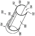
部分内部套筒(180)在远侧部分(182)与近侧部分(184)之间延伸。部分内部套筒(180)包括限定纵向延伸的推拉缆线凹部(186)的外表面(188)和内表面(190)。内表面(190)和外表面(188)在纵向延伸的套筒边缘(192)之间成角度地延伸,其一起限定纵向延伸的间隙(194)(如图11中最佳所见)。换句话说,内表面(190)和外表面(188)不像外部套筒(170)那样在整个360度角范围内以连续方式成角度地延伸;而是终止于纵向延伸的套筒边缘(192)中。又换句话说,如图10中最佳所见,部分内部套筒(180)具有月牙形形状或“C”形。根据本文的教导内容,表面(188,190)可以延伸任何合适的角距离,以限定任何适当尺寸的间隙(194),这对于本领域的技术人员而言将是显而易见的。在一些情况下,部分内部套筒(180)可以仅覆盖内表面挠曲主体(158)的一部分,使得间隙(159)部分暴露。A portion of the inner sleeve (180) extends between the distal portion (182) and the proximal portion (184). The partial inner sleeve (180) includes an outer surface (188) and an inner surface (190) defining a longitudinally extending push-pull cable recess (186). Inner surface (190) and outer surface (188) extend angularly between longitudinally extending sleeve edges (192), which together define a longitudinally extending gap (194) (best seen in Figure 11). In other words, the inner surface (190) and outer surface (188) do not angularly extend in a continuous manner throughout the full 360 degree angle of the outer sleeve (170); rather, they terminate in a longitudinally extending sleeve edge ( 192). In still other words, as best seen in Figure 10, the portion of the inner sleeve (180) has a crescent shape or "C" shape. Surfaces (188, 190) may extend any suitable angular distance to define gaps (194) of any suitable size, as will be apparent to those skilled in the art in light of the teachings herein. In some cases, a portion of the inner sleeve (180) may cover only a portion of the inner surface flexure body (158), leaving the gap (159) partially exposed.
部分内部套筒(180)容纳在末端主体(160)的内部以及内部管腔(162)内,使得外表面(188)与末端主体(160)的内表面以及挠曲主体(158)的内表面适当接触。根据本文的教导内容,外表面(188)可通过任何合适的手段(诸如胶合等)与末端主体(160)的内表面和/或挠曲主体(158)的内表面充分联接,这对于本领域的技术人员而言将是显而易见的。在一些情况下,部分内部套筒(180)不联接到末端主体(160)或挠曲主体(158)。A portion of the inner sleeve (180) is received inside the tip body (160) and within the inner lumen (162) such that the outer surface (188) is connected to the inner surface of the tip body (160) and the inner surface of the flexure body (158) appropriate contact. Outer surface (188) may be substantially coupled to the inner surface of tip body (160) and/or the inner surface of flexure body (158) by any suitable means, such as gluing, etc., in accordance with the teachings herein, as is known in the art will be obvious to the skilled person. In some cases, the portion of the inner sleeve (180) is not coupled to the tip body (160) or the flexure body (158).
如图9至图10中最佳所见,推拉缆线凹部(186)的尺寸被设计为容纳推拉缆线(34),使得推拉缆线(34)可以插置在部分内部套筒(180)的外表面(188)与挠曲主体(158)的内表面之间。根据本文的描述,如图12中最佳所见,部分内部套筒(180)的近侧部分(184)限定通孔(196)以容纳推拉缆线(34),从而朝向柄部组件(12)朝近侧延伸。在一些情况下,衬里材料可以插置在推拉缆线(34)和推拉缆线凹部(186)之间。在一些情况下,外表面(188)内的预成形凹部不存在,使得当推拉缆线(34)插置在内部套筒(180)与挠曲主体(158)的内表面之间时最初形成凹部。As best seen in Figures 9-10, the push-pull cable recess (186) is sized to accommodate the push-pull cable (34) so that the push-pull cable (34) can be inserted into part of the inner sleeve (180) between the outer surface (188) of the flexure body (158) and the inner surface of the flexure body (158). According to the description herein, as best seen in FIG. 12 , the proximal portion ( 184 ) of the partial inner sleeve ( 180 ) defines a through hole ( 196 ) to accommodate the push-pull cable ( 34 ) toward the handle assembly ( 12 ). ) extends proximally. In some cases, a liner material may be interposed between the push-pull cable (34) and the push-pull cable recess (186). In some cases, the pre-formed recesses in the outer surface (188) are absent such that the push-pull cable (34) is initially formed when the push-pull cable (34) is interposed between the inner sleeve (180) and the inner surface of the flexure body (158). recess.
推拉缆线(34)可以胶合到推拉缆线凹部(186)的相邻部分或衬里材料。然而,根据本文的教导内容,推拉缆线(34)可使用任何合适的方式与推拉缆线凹部(186)的相邻部分或衬里材料联接,这对于本领域的技术人员而言将是显而易见的。胶合或以其他方式将推拉缆线(34)与内部套筒(180)的外表面(188)联接可以防止内部套筒(180)由于柔性导轴部分(154)在关节运动位置(如图3B所示)和非关节运动位置(如图3A所示)之间转变而引起的翘曲或以其他方式变形。The push-pull cable (34) may be glued to an adjacent portion or lining material of the push-pull cable recess (186). However, push-pull cable (34) may be coupled to adjacent portions of push-pull cable recess (186) or lining material using any suitable means, as will be apparent to those skilled in the art in light of the teachings herein . Gluing or otherwise coupling the push-pull cable (34) to the outer surface (188) of the inner sleeve (180) can prevent the inner sleeve (180) from being in an articulated position due to the flexible guide shaft portion (154) (Fig. 3B). Warping or otherwise deforming due to transitions between the transitions between the non-articulating position (shown in Figure 3A).
如图9至图10中最佳所见,纵向延伸的套筒边缘(192)纵向设置在内部管腔(162)内,使得套筒边缘(192)与挠曲切口(153)相邻。另外,套筒边缘(192)与弹性脊(151)横向隔离开,使得纵向延伸的间隙(194)直接与弹性脊(151)相邻地延伸。As best seen in Figures 9-10, the longitudinally extending sleeve edge (192) is disposed longitudinally within the inner lumen (162) such that the sleeve edge (192) is adjacent the flex cutout (153). Additionally, the sleeve edge (192) is laterally spaced apart from the resilient ridge (151) such that the longitudinally extending gap (194) extends directly adjacent the resilient ridge (151).
部分内部套筒(180)的终止端部(包括套筒边缘(192))可以适当地与内部管腔(162)、刚性导轴部分(152)和末端主体(160)的相应部分联接,以便充分防止内部管腔(162)和间隙(159)和/或挠曲切口(153)之间的不期望量的流体连通。因此,部分内部套筒(180)可充分覆盖间隙(159)和挠曲切口(153)以便防止不期望量的空气/流体从间隙(159)和挠曲切口(153)中逸出/漏出。部分内部套筒(180)可符合挠曲主体(158)的轮廓同时还防止流体通过间隙(159)逸出,从而促进抽吸/冲洗源(17)和开口远侧末端(156)之间的合适流体连通。在一些情况下,部分内部套筒(180)可以防止足够量的空气/流体逸出/漏出,使得外部套筒(170)可以省略。然而,在其他情况下,部分内部套筒(180)和外部套筒(170)可以一起协作以便防止足够量的空气/流体逸出/漏出。然而,在其他情况下,部分内部套筒(180)可以不被构造成防止不期望量的空气/流体逸出,使得外部套筒(170)防止合适量的空气/流体逸出/漏出。The terminating end of the portion of the inner sleeve (180), including the sleeve edge (192), may be suitably coupled with the inner lumen (162), rigid guide shaft portion (152) and corresponding portions of the tip body (160) so as to An undesired amount of fluid communication between the inner lumen (162) and the gap (159) and/or flex cutout (153) is substantially prevented. Thus, a portion of the inner sleeve (180) can adequately cover the gap (159) and flex cutout (153) to prevent undesired amounts of air/fluid from escaping/leakage from the gap (159) and flex cutout (153). Part of the inner sleeve (180) can conform to the contours of the flexure body (158) while also preventing fluid from escaping through the gap (159), thereby facilitating communication between the suction/irrigation source (17) and the open distal tip (156). Suitable fluid communication. In some cases, a portion of the inner sleeve (180) may prevent a sufficient amount of air/fluid from escaping/leaking so that the outer sleeve (170) may be omitted. However, in other cases, portions of the inner sleeve (180) and outer sleeve (170) may cooperate together to prevent a sufficient amount of air/fluid from escaping/leaking. However, in other cases, the portion of the inner sleeve (180) may not be configured to prevent the escape of undesired amounts of air/fluid, such that the outer sleeve (170) prevents the escape/leak of a suitable amount of air/fluid.
根据以上描述,部分内部套筒(180)由适当柔性的材料形成,使得部分内部套筒(180)可与挠曲主体(158)一起挠曲以便适应开口远侧末端(156)的关节运动。如图10中最佳所示,纵向延伸的间隙(194)横向延伸合适的距离,使得当挠曲主体(158)朝向关节运动构型弯曲时,部分内部套筒(180)不会在导丝(62)和可充胀球囊(78)从柔性导轴部分(154)朝近侧移除时在内部管腔(162)内自身塌缩。如果部分内部套筒(180)在处于关节运动构型时在内部管腔(162)内自身塌缩,则开口远侧末端(56)和抽吸/冲洗源(17)之间的流体连通可能会被不期望地中断/阻挡。如果内部套筒(180)以连续方式成角度地延伸(就像外部套筒(170)一样),或者如果间隙(194)不够宽,则容纳在内部管腔(162)内的内部套筒(180)自身塌缩的可能性可能更大。因此,由于内部套筒(180)不以连续方式成角度地延伸,部分内部套筒(180)可以在处于关节运动构型时防止自身塌缩。According to the above description, the portion of the inner sleeve (180) is formed from a suitably flexible material such that the portion of the inner sleeve (180) can flex with the flexure body (158) to accommodate articulation of the open distal tip (156). As best shown in Figure 10, the longitudinally extending gap (194) extends laterally a suitable distance so that when the flexure body (158) is flexed toward the articulation configuration, a portion of the inner sleeve (180) does not slide over the guidewire (62) and inflatable balloon (78) collapse upon itself within inner lumen (162) upon proximal removal from flexible guide shaft portion (154). Fluid communication between the open distal tip (56) and the suction/irrigation source (17) may be possible if part of the inner sleeve (180) collapses itself within the inner lumen (162) when in the articulating configuration Can be interrupted/blocked unexpectedly. If the inner sleeve (180) extends angularly in a continuous fashion (as the outer sleeve (170) does), or if the gap (194) is not wide enough, the inner sleeve ( 180) may be more likely to collapse on its own. Thus, since the inner sleeve (180) does not angularly extend in a continuous manner, a portion of the inner sleeve (180) may prevent itself from collapsing when in the articulating configuration.
如图9中最佳所见,套筒(180)的内表面(190)位于内部管腔(162)内以便在可充胀球囊(78)的前进和/或回缩期间防止可充胀球囊(78)钩住或接触柔性主体(158)的限定间隙(159)的部分,以及在开口远侧末端(156)的关节运动期间保护可充胀球囊(78)不被挠曲主体(158)的限定间隙(159)的部分夹紧。因此,根据本文的描述,部分内部套筒(180)可保护可充胀球囊(78)免受不期望的损坏,同时还允许抽吸/冲洗源(17)在示例性使用期间以关节运动构型在导向导管组件(50)的开口远侧末端(56)处提供抽吸/冲洗。As best seen in Figure 9, the inner surface (190) of the sleeve (180) is located within the inner lumen (162) to prevent inflatable during advancement and/or retraction of the inflatable balloon (78). The balloon (78) hooks or contacts the portion of the flexible body (158) that defines the gap (159) and protects the inflatable balloon (78) from flexing the body during articulation of the open distal tip (156) The portion of (158) defining the gap (159) clamps. Thus, in accordance with the description herein, a portion of the inner sleeve (180) may protect the inflatable balloon (78) from undesired damage, while also allowing the suction/irrigation source (17) to articulate during exemplary use The configuration provides suction/irrigation at the open distal tip (56) of the guide catheter assembly (50).
III.示例性组合III. Exemplary Combinations
以下实施例涉及本文的教导内容可被组合或应用的各种非穷尽性方式。应当理解,以下实施例并非旨在限制可在本专利申请或本专利申请的后续提交文件中的任何时间提供的任何权利要求的覆盖范围。不旨在进行免责声明。提供以下实施例仅仅是出于例示性目的。预期本文的各种教导内容可按多种其他方式进行布置和应用。还设想到,一些变型可省略在以下实施例中所提及的某些特征。因此,下文提及的方面或特征中的任一者均不应被视为决定性的,除非另外例如由发明人或关注发明人的继承者在稍后日期明确指明如此。如果本专利申请或与本专利申请相关的后续提交文件中提出的任何权利要求包括下文提及的那些特征之外的附加特征,则这些附加特征不应被假定为因与专利性相关的任何原因而被添加。The following examples are directed to various non-exhaustive ways in which the teachings herein may be combined or applied. It should be understood that the following examples are not intended to limit the scope of coverage of any claims that may be presented at any time in this patent application or subsequent filings of this patent application. Not intended to make a disclaimer. The following examples are provided for illustrative purposes only. It is contemplated that the various teachings herein can be arranged and applied in a variety of other ways. It is also contemplated that some variations may omit certain features mentioned in the following embodiments. Accordingly, any of the aspects or features mentioned below should not be considered conclusive unless otherwise expressly indicated to do so at a later date, eg, by the inventor or a successor of the inventor concerned. If any claims presented in this patent application or in subsequent filings related to this patent application include additional features than those mentioned below, such additional features shall not be presumed for any reason related to patentability was added.
实施例1Example 1
一种导管系统,包括:(a)主体;(b)导向构件组件,所述导向构件组件从所述主体朝远侧延伸,其中所述导向构件组件包括:(i)近侧刚性部分,所述近侧刚性部分限定纵向轴线;(ii)远侧柔性部分;和(iii)开口远侧端部,其中所述导向构件组件限定管腔,其中所述管腔所述主体与所述开口远侧端部之间连通;(c)关节运动组件,所述关节运动组件操作地联接到所述远侧柔性部分,其中所述关节运动组件被构造成使所述远侧柔性部分和所述开口远侧端部相对于所述纵向轴线在笔直构型与关节运动构型之间挠曲;和(d)部分套筒,所述部分套筒设置在由所述远侧柔性部分限定的所述管腔的一部分内,其中所述部分套筒限定纵向延伸的间隙。A catheter system comprising: (a) a body; (b) a guide member assembly extending distally from the body, wherein the guide member assembly includes: (i) a proximal rigid portion, the The proximal rigid portion defines a longitudinal axis; (ii) a distal flexible portion; and (iii) an open distal end, wherein the guide member assembly defines a lumen, wherein the body of the lumen is distal to the opening communication between the side ends; (c) an articulation assembly operatively coupled to the distal flexible portion, wherein the articulation assembly is configured to connect the distal flexible portion and the opening a distal end flexes between a straight configuration and an articulating configuration relative to the longitudinal axis; and (d) a partial sleeve disposed within the portion defined by the distal flexible portion within a portion of the lumen, wherein the portion of the sleeve defines a longitudinally extending gap.
实施例2Example 2
根据实施例1所述的导管系统,其中所述部分套筒包括月牙形形状。The catheter system of embodiment 1, wherein the partial sleeve includes a crescent shape.
实施例3Example 3
根据实施例1至2中任一项或多项所述的导管系统,其中所述远侧柔性部分包括弹性脊。The catheter system of any one or more of Embodiments 1-2, wherein the distal flexible portion comprises an elastic ridge.
实施例4Example 4
根据实施例3所述的导管系统,其中所述纵向延伸的间隙与所述弹性脊直接相邻。The catheter system of embodiment 3, wherein the longitudinally extending gap is directly adjacent the elastic ridge.
实施例5Example 5
根据实施例1至4中任一项或多项所述的导管系统,其中所述远侧柔性部分包括柔性主体阵列,其中相邻的柔性主体限定可调节间隙,所述可调节间隙被构造成响应于所述远侧柔性部分在所述笔直构型与所述关节运动构型之间挠曲而改变尺寸。The catheter system of any one or more of embodiments 1-4, wherein the distal flexible portion comprises an array of flexible bodies, wherein adjacent flexible bodies define adjustable gaps configured to The size changes in response to the distal flexible portion flexing between the straight configuration and the articulating configuration.
实施例6Example 6
根据实施例5所述的导管系统,其中所述部分套筒覆盖由所述柔性主体限定的所述可调节间隙。The catheter system of
实施例7Example 7
根据实施例6所述的导管系统,还包括可滑动地设置在所述管腔内的工作元件。The catheter system of embodiment 6, further comprising a working element slidably disposed within the lumen.
实施例8Example 8
根据实施例7所述的导管系统,其中所述工作元件还包括可充胀球囊。The catheter system of embodiment 7, wherein the working element further comprises an inflatable balloon.
实施例9Example 9
根据实施例8所述的导管系统,其中所述内部套筒被构造和定位成将所述可充胀球囊与由所述柔性主体限定的所述可调节间隙隔离开。The catheter system of embodiment 8, wherein the inner sleeve is constructed and positioned to isolate the inflatable balloon from the adjustable gap defined by the flexible body.
实施例10Example 10
根据实施例1至9中任一项或多项所述的导管系统,还包括与所述导向构件组件的开口远侧末端流体连通的抽吸源或冲洗源。The catheter system of any one or more of Embodiments 1 to 9, further comprising a suction or irrigation source in fluid communication with the open distal tip of the guide member assembly.
实施例11Example 11
根据实施例10所述的导管系统,其中所述远侧柔性部分限定多个可调节间隙,其中所述部分套筒充分覆盖所述可调节间隙以促进所述开口远侧末端与所述抽吸源或所述冲洗源之间的流体连通。The catheter system of
实施例12Example 12
根据实施例1至11中任一项或多项所述的导管系统,其中所述关节运动组件包括推拉缆线。The catheter system of any one or more of embodiments 1-11, wherein the articulation assembly includes a push-pull cable.
实施例13Example 13
根据实施例12所述的导管系统,其中所述部分套筒限定容纳所述推拉缆线的纵向延伸的凹部。The catheter system of
实施例14Example 14
根据实施例13所述的导管系统,其中所述推拉缆线插置在所述纵向延伸的凹部与所述远侧柔性部分的内表面之间。The catheter system of embodiment 13, wherein the push-pull cable is interposed between the longitudinally extending recess and the inner surface of the distal flexible portion.
实施例15Example 15
根据实施例14所述的导管系统,还包括设置在所述推拉缆线与所述纵向延伸的凹部之间的衬里。The catheter system of
实施例16Example 16
根据实施例12至15中任一项或多项所述的导管系统,其中所述推拉缆线与所述部分套筒联接。The catheter system of any one or more of
实施例17Example 17
根据实施例1至16中任一项或多项所述的导管系统,还包括设置在所述远侧柔性部分的外部上的外部套筒。The catheter system of any one or more of Embodiments 1 to 16, further comprising an outer sleeve disposed on the exterior of the distal flexible portion.
实施例18Example 18
一种导管系统,包括:(a)主体;(b)导向构件组件,所述导向构件组件从所述主体朝远侧延伸,其中所述导向构件组件包括:(i)近侧刚性部分,所述近侧刚性部分限定纵向轴线;(ii)远侧柔性部分,所述远侧柔性部分包括纵向延伸的弹性脊和限定多个可调节间隙的多个挠曲主体;和(iii)开口远侧端部,其中所述导向构件组件限定管腔,其中所述管腔在所述主体与所述开口远侧端部之间连通;(c)关节运动组件,所述关节运动组件操作地联接到所述远侧柔性部分,其中所述关节运动组件被构造成使所述远侧柔性部分和所述开口远侧端部相对于所述纵向轴线在笔直构型与关节运动构型之间挠曲;和(d)部分套筒,所述部分套筒设置在由所述远侧柔性部分限定的所述管腔的一部分内,其中所述部分套筒限定纵向延伸的间隙,所述纵向延伸的间隙与所述纵向延伸的弹性脊相邻地延伸。A catheter system comprising: (a) a body; (b) a guide member assembly extending distally from the body, wherein the guide member assembly includes: (i) a proximal rigid portion, the the proximal rigid portion defines a longitudinal axis; (ii) a distal flexible portion comprising a longitudinally extending elastic ridge and a plurality of flexure bodies defining a plurality of adjustable gaps; and (iii) an open distal end an end, wherein the guide member assembly defines a lumen, wherein the lumen communicates between the body and the open distal end; (c) an articulation assembly operatively coupled to the distal flexible portion, wherein the articulation assembly is configured to flex the distal flexible portion and the open distal end relative to the longitudinal axis between a straight configuration and an articulation configuration and (d) a partial sleeve disposed within a portion of the lumen defined by the distal flexible portion, wherein the partial sleeve defines a longitudinally extending gap, the longitudinally extending A gap extends adjacent the longitudinally extending elastic ridge.
实施例19Example 19
根据实施例18所述的导管系统,其中所述部分套筒覆盖所述多个可调节间隙。The catheter system of embodiment 18, wherein the partial sleeve covers the plurality of adjustable gaps.
实施例20Example 20
一种导管系统,包括:(a)主体;(b)导向构件组件,所述导向构件组件从所述主体朝远侧延伸,其中所述导向构件组件包括:(i)近侧刚性部分,所述近侧刚性部分限定纵向轴线;(ii)远侧柔性部分,所述远侧柔性部分被构造成使所述远侧柔性部分和开口远侧端部相对于所述纵向轴线在笔直构型与关节运动构型之间挠曲,其中所述远侧柔性部分在所述笔直构型中限定多个间隙;和(iii)开口远侧端部,其中所述导向构件组件限定管腔,其中所述管腔在所述主体与所述开口远侧端部之间连通;(c)部分套筒,所述部分套筒设置在所述远侧柔性部分内,其中所述部分套筒限定纵向延伸的间隙,其中所述部分套筒覆盖所述笔直构型中的所述多个间隙。A catheter system comprising: (a) a body; (b) a guide member assembly extending distally from the body, wherein the guide member assembly includes: (i) a proximal rigid portion, the The proximal rigid portion defines a longitudinal axis; (ii) a distal flexible portion configured such that the distal flexible portion and the open distal end are in a straight configuration with respect to the longitudinal axis; flexing between articulation configurations, wherein the distal flexible portion defines a plurality of gaps in the straight configuration; and (iii) an open distal end, wherein the guide member assembly defines a lumen, wherein the the lumen communicates between the body and the open distal end; (c) a partial sleeve disposed within the distal flexible portion, wherein the partial sleeve defines a longitudinal extension of gaps, wherein the partial sleeve covers the plurality of gaps in the straight configuration.
IV.杂项IV. Miscellaneous
应当理解,本文所述的任何示例还可包括除上述那些之外或代替上述那些的各种其他特征。仅以举例的方式,本文所述的任何示例还可包括以引用方式并入本文的各种参考文献中任何一者中公开的各种特征中的一种或多种。It should be understood that any examples described herein may also include various other features in addition to or in place of those described above. By way of example only, any examples described herein may also include one or more of the various features disclosed in any of the various references incorporated herein by reference.
应当理解,本文所述的教导内容、表达、实施方案、示例等中的任何一者或多者可与本文所述的其他教导内容、表达、实施方案、示例等中的任何一者或多者进行组合。因此,上述教导内容、表达、实施方案、示例等不应被视为彼此孤立。根据本文的教导内容,本文的教导内容可进行组合的各种合适方式对于本领域的普通技术人员而言将显而易见。此类修改和变型旨在包括在权利要求书的范围内。It is to be understood that any one or more of the teachings, expressions, embodiments, examples, etc. described herein may be combined with any one or more of other teachings, expressions, embodiments, examples, etc. described herein Make combinations. Accordingly, the above teachings, expressions, embodiments, examples, etc. should not be considered in isolation from each other. Various suitable ways in which the teachings herein may be combined will be apparent to those of ordinary skill in the art in view of the teachings herein. Such modifications and variations are intended to be included within the scope of the claims.
应当理解,据称以引用方式并入本文的任何专利、专利公布或其他公开材料,无论是全文或部分,仅在所并入的材料与本公开中所述的现有定义、陈述或者其他公开材料不冲突的范围内并入本文。因此,并且在必要的程度下,本文明确列出的公开内容代替以引用方式并入本文的任何冲突材料。据称以引用方式并入本文但与本文列出的现有定义、陈述或其他公开材料相冲突的任何材料或其部分,将仅在所并入的材料与现有的公开材料之间不产生冲突的程度下并入。It should be understood that any patent, patent publication or other published material, whether in whole or in part, said to be incorporated herein by reference is only intended to be consistent with existing definitions, representations or other disclosures set forth in this disclosure by the incorporated material. Materials are incorporated herein to the extent that they do not conflict. Accordingly, and to the extent necessary, the disclosure expressly set forth herein supersedes any conflicting material incorporated herein by reference. Any material, or portion thereof, purportedly incorporated herein by reference, but which conflicts with existing definitions, statements, or other disclosed material set forth herein, will not arise only between the incorporated material and the existing disclosed material merged to the extent of conflict.
本文所公开的装置的型式可设计为使用一次后丢弃,也可设计为供多次使用。在任一种情况下或两种情况下,可对这些型式进行修复以在至少一次使用之后重复使用。修复可包括以下步骤的任意组合:拆卸装置,然后清洁或替换特定零件以及随后进行重新组装。具体地,可拆卸所述装置的型式,并且可选择性地以任何组合形式来更换或拆除所述装置的任意数量的特定部件或零件。在清洁和/或更换特定零件时,所述装置的型式可在修复设施中进行重新组装以供随后使用,或者在即将进行外科手术前由外科团队进行重新组装。本领域的技术人员将会了解,装置的修复可利用多种技术进行拆卸、清洁/更换、以及重新组装。此类技术的使用以及所得的修复装置均在本申请的范围内。The devices disclosed herein can be designed to be disposed of after a single use, or they can be designed to be used multiple times. In either or both cases, these versions can be reconditioned for reuse after at least one use. Repair can include any combination of the following steps: disassembly of the device, followed by cleaning or replacement of specific parts and subsequent reassembly. In particular, the type of device may be disassembled, and any number of particular components or parts of the device may be selectively replaced or removed in any combination. The version of the device can be reassembled in a repair facility for subsequent use when certain parts are cleaned and/or replaced, or by a surgical team just before surgery. Those skilled in the art will appreciate that the repair of the device can utilize a variety of techniques for disassembly, cleaning/replacement, and reassembly. The use of such techniques and the resulting prosthetic devices are within the scope of this application.
仅以举例的方式,本文所述的型式可在外科手术之前进行处理。首先,可以获取新的或用过的器械,并且根据需要进行清洁。然后,可对器械进行消毒。在一种消毒技术中,将所述器械放置在密闭且密封的容器(诸如,塑料或TYVEK袋)中。然后可将容器和器械置于可穿透所述容器的辐射场,诸如γ辐射、x射线或高能电子。辐射可杀死器械上和容器中的细菌。经消毒的器械随后可被储存在无菌容器中。密封的容器可使器械保持无菌,直到在外科设施中打开所述容器。还可使用本领域已知的任何其他技术对装置进行消毒,所述技术包括但不限于β辐射或γ辐射、环氧乙烷或蒸汽。By way of example only, the versions described herein may be processed prior to surgery. First, new or used instruments can be obtained and cleaned as needed. The instruments can then be sterilized. In one sterilization technique, the instrument is placed in a closed and sealed container, such as a plastic or TYVEK bag. The container and device can then be exposed to a radiation field, such as gamma radiation, x-rays, or high-energy electrons, that can penetrate the container. Radiation kills bacteria on instruments and in containers. The sterilized instruments can then be stored in sterile containers. A sealed container keeps the instrument sterile until the container is opened in a surgical facility. The device may also be sterilized using any other technique known in the art, including but not limited to beta or gamma radiation, ethylene oxide, or steam.
在已经示出并描述了本发明的各种型式的情况下,通过本领域的普通技术人员在不脱离本发明范围的前提下进行适当修改来实现对本文所述方法和系统的进一步改进。已经提及了若干此类可能的修改,并且其他修改对于本领域的技术人员而言将显而易见。例如,上文所讨论的示例、型式、几何形状、材料、尺寸、比率、步骤等等均是示例性的而非必需的。因此,本发明的范围应根据以下权利要求书来考虑,并且应理解为不限于说明书和附图中示出和描述的结构和操作的细节。Having shown and described various versions of the invention, further improvements to the methods and systems described herein can be realized by those of ordinary skill in the art with appropriate modifications without departing from the scope of the invention. Several such possible modifications have been mentioned, and others will be apparent to those skilled in the art. For example, the examples, styles, geometries, materials, dimensions, ratios, steps, etc. discussed above are exemplary and not required. Accordingly, the scope of the invention should be considered in terms of the following claims and should not be understood to be limited to the details of construction and operation shown and described in the specification and drawings.
Claims (20)
Applications Claiming Priority (5)
| Application Number | Priority Date | Filing Date | Title |
|---|---|---|---|
| US201962934005P | 2019-11-12 | 2019-11-12 | |
| US62/934005 | 2019-11-12 | ||
| US17/067872 | 2020-10-12 | ||
| US17/067,872 US11944769B2 (en) | 2019-11-12 | 2020-10-12 | Steerable guide with partial sleeve |
| PCT/IB2020/060618 WO2021094945A1 (en) | 2019-11-12 | 2020-11-11 | Steerable guide with partial sleeve |
Publications (2)
| Publication Number | Publication Date |
|---|---|
| CN114980794A true CN114980794A (en) | 2022-08-30 |
| CN114980794B CN114980794B (en) | 2025-03-07 |
Family
ID=75846186
Family Applications (1)
| Application Number | Title | Priority Date | Filing Date |
|---|---|---|---|
| CN202080092735.5A Active CN114980794B (en) | 2019-11-12 | 2020-11-11 | Steerable guide device with partial sleeve |
Country Status (5)
| Country | Link |
|---|---|
| US (2) | US11944769B2 (en) |
| EP (1) | EP4057884B1 (en) |
| JP (1) | JP7539982B2 (en) |
| CN (1) | CN114980794B (en) |
| WO (1) | WO2021094945A1 (en) |
Cited By (1)
| Publication number | Priority date | Publication date | Assignee | Title |
|---|---|---|---|---|
| CN119345571A (en) * | 2024-10-18 | 2025-01-24 | 深圳市恒实医疗科技有限公司 | A catheter rotating structure and a blade balloon |
Families Citing this family (2)
| Publication number | Priority date | Publication date | Assignee | Title |
|---|---|---|---|---|
| USD1039141S1 (en) * | 2020-04-27 | 2024-08-13 | Acclarent, Inc. | Flex section in shaft for ENT instrument |
| CN113599662B (en) * | 2021-07-09 | 2023-03-21 | 张明泽 | Drainage tube convenient to lay under peritoneoscope |
Citations (5)
| Publication number | Priority date | Publication date | Assignee | Title |
|---|---|---|---|---|
| US20050020974A1 (en) * | 2000-08-23 | 2005-01-27 | Norborn Medical, Inc. | Steerable distal support system |
| JP2006051346A (en) * | 2004-07-15 | 2006-02-23 | Tatsuo Kumazaki | Drug perfusion method for para-aortic lymph node tumor, sheath for catheter insertion, introducer for catheter insertion, and perfusion device |
| US20080300462A1 (en) * | 2007-05-31 | 2008-12-04 | Boston Scientific Scimed, Inc. | Active controlled bending in medical devices |
| US20180185018A1 (en) * | 2016-12-30 | 2018-07-05 | Boston Scientific Scimed, Inc. | System for a minimally-invasive treatment within a body lumen |
| CN110198654A (en) * | 2017-01-20 | 2019-09-03 | 波士顿科学国际有限公司 | System for minimal invasive operation |
Family Cites Families (17)
| Publication number | Priority date | Publication date | Assignee | Title |
|---|---|---|---|---|
| US4711406A (en) * | 1986-06-02 | 1987-12-08 | Barstow Kenneth T | Coreholder |
| WO1993013704A1 (en) * | 1992-01-09 | 1993-07-22 | Endomedix Corporation | Bi-directional miniscope |
| AU8764998A (en) | 1997-09-04 | 1999-03-22 | Alcon Laboratories, Inc. | Flexible tube with circular grooves of varying width and depth |
| US7840261B2 (en) | 2002-06-05 | 2010-11-23 | Biocardia, Inc. | Catheter systems and methods for placing bi-ventricular pacing leads |
| US8083671B2 (en) * | 2004-09-30 | 2011-12-27 | Boston Scientific Scimed, Inc. | Fluid delivery system for use with an endoscope |
| US20070225750A1 (en) * | 2006-03-10 | 2007-09-27 | Brooke Ren | Embolic protection systems |
| WO2008039800A2 (en) | 2006-09-25 | 2008-04-03 | Valentx, Inc. | Toposcopic access and delivery devices |
| US9986896B2 (en) * | 2008-03-05 | 2018-06-05 | The Board Of Regents Of The University Of Texas System | Disposable sheath designs for the stimulating endoscope and needle endoscopes having distal electrodes for nerve block under direct vision and methods for making and using same |
| EP2398543A1 (en) * | 2009-02-20 | 2011-12-28 | Boston Scientific Scimed, Inc. | Asymmetric dual directional steerable catheter sheath |
| US9155492B2 (en) | 2010-09-24 | 2015-10-13 | Acclarent, Inc. | Sinus illumination lightwire device |
| US11033716B2 (en) * | 2015-01-12 | 2021-06-15 | Intuitive Surgical Operations, Inc. | Devices, systems, and methods for anchoring actuation wires to a steerable instrument |
| US9757018B2 (en) | 2015-03-31 | 2017-09-12 | Acclarent, Inc. | Medical guidewire with integral light transmission |
| JP6882995B2 (en) | 2015-07-17 | 2021-06-02 | コーニンクレッカ フィリップス エヌ ヴェKoninklijke Philips N.V. | Intravascular devices, systems and methods using adhesively attached molded ribbons |
| US10610308B2 (en) | 2017-02-01 | 2020-04-07 | Acclarent, Inc. | Navigation guidewire with interlocked coils |
| US11376401B2 (en) | 2017-04-26 | 2022-07-05 | Acclarent, Inc. | Deflectable guide for medical instrument |
| US11027105B2 (en) | 2017-07-13 | 2021-06-08 | Biosense Webster (Israel) Ltd. | Adjustable instrument for dilation of anatomical passageway |
| US20190091438A1 (en) | 2017-09-26 | 2019-03-28 | Cardiovascular Systems, Inc. | Catheter with side ports and methods of use |
-
2020
- 2020-10-12 US US17/067,872 patent/US11944769B2/en active Active
- 2020-11-11 CN CN202080092735.5A patent/CN114980794B/en active Active
- 2020-11-11 WO PCT/IB2020/060618 patent/WO2021094945A1/en active IP Right Grant
- 2020-11-11 JP JP2022527138A patent/JP7539982B2/en active Active
- 2020-11-11 EP EP20808522.5A patent/EP4057884B1/en active Active
-
2024
- 2024-02-26 US US18/586,857 patent/US20240198065A1/en not_active Abandoned
Patent Citations (5)
| Publication number | Priority date | Publication date | Assignee | Title |
|---|---|---|---|---|
| US20050020974A1 (en) * | 2000-08-23 | 2005-01-27 | Norborn Medical, Inc. | Steerable distal support system |
| JP2006051346A (en) * | 2004-07-15 | 2006-02-23 | Tatsuo Kumazaki | Drug perfusion method for para-aortic lymph node tumor, sheath for catheter insertion, introducer for catheter insertion, and perfusion device |
| US20080300462A1 (en) * | 2007-05-31 | 2008-12-04 | Boston Scientific Scimed, Inc. | Active controlled bending in medical devices |
| US20180185018A1 (en) * | 2016-12-30 | 2018-07-05 | Boston Scientific Scimed, Inc. | System for a minimally-invasive treatment within a body lumen |
| CN110198654A (en) * | 2017-01-20 | 2019-09-03 | 波士顿科学国际有限公司 | System for minimal invasive operation |
Cited By (1)
| Publication number | Priority date | Publication date | Assignee | Title |
|---|---|---|---|---|
| CN119345571A (en) * | 2024-10-18 | 2025-01-24 | 深圳市恒实医疗科技有限公司 | A catheter rotating structure and a blade balloon |
Also Published As
| Publication number | Publication date |
|---|---|
| EP4057884A1 (en) | 2022-09-21 |
| CN114980794B (en) | 2025-03-07 |
| US20210138212A1 (en) | 2021-05-13 |
| JP2023501532A (en) | 2023-01-18 |
| US11944769B2 (en) | 2024-04-02 |
| EP4057884C0 (en) | 2023-08-02 |
| US20240198065A1 (en) | 2024-06-20 |
| JP7539982B2 (en) | 2024-08-26 |
| EP4057884B1 (en) | 2023-08-02 |
| WO2021094945A1 (en) | 2021-05-20 |
Similar Documents
| Publication | Publication Date | Title |
|---|---|---|
| US12357791B2 (en) | Deflectable guide for medical instrument | |
| CN109862934B (en) | Dilation system | |
| JP7242629B2 (en) | Adjustable instrument for dilating an anatomical passageway | |
| CN115666701A (en) | Shaft deflection control assembly for ENT guide instruments | |
| US20240198065A1 (en) | Steerable guide with partial sleeve | |
| US20160310714A1 (en) | Balloon dilation system with malleable internal guide | |
| CN108778161A (en) | Dilating catheter component with quick variation component | |
| CN110248589A (en) | Navigation seal wire with interlocking coil | |
| CN115697221A (en) | ENT guide with advanceable instrument and advanceable endoscope shaft | |
| US12138410B2 (en) | Sinuplasty instrument with deflectable guide rail | |
| CN110833454A (en) | Endoscope with anatomical lift assembly | |
| CN107666852B (en) | Illuminated guidewire with optical sensing | |
| US10987497B2 (en) | Balloon catheter with tactile feedback features and reinforced lumen | |
| CN113164182B (en) | Devices with integrated imaging and irrigation features | |
| CN113164187B (en) | Bidirectional articulating surgical razor | |
| JP7262969B2 (en) | Suction device with bipolar RF cuff |
Legal Events
| Date | Code | Title | Description |
|---|---|---|---|
| PB01 | Publication | ||
| PB01 | Publication | ||
| SE01 | Entry into force of request for substantive examination | ||
| SE01 | Entry into force of request for substantive examination | ||
| GR01 | Patent grant | ||
| GR01 | Patent grant |