CN114454024B - Wafer Processing Equipment - Google Patents
Wafer Processing Equipment Download PDFInfo
- Publication number
- CN114454024B CN114454024B CN202110232675.9A CN202110232675A CN114454024B CN 114454024 B CN114454024 B CN 114454024B CN 202110232675 A CN202110232675 A CN 202110232675A CN 114454024 B CN114454024 B CN 114454024B
- Authority
- CN
- China
- Prior art keywords
- wafer
- module
- grinding
- grinding wheel
- detection module
- Prior art date
- Legal status (The legal status is an assumption and is not a legal conclusion. Google has not performed a legal analysis and makes no representation as to the accuracy of the status listed.)
- Active
Links
- 238000012545 processing Methods 0.000 title claims abstract description 54
- 238000000227 grinding Methods 0.000 claims abstract description 176
- 238000001514 detection method Methods 0.000 claims abstract description 103
- 238000001179 sorption measurement Methods 0.000 claims abstract description 37
- 238000000034 method Methods 0.000 claims abstract description 27
- 230000008569 process Effects 0.000 claims abstract description 26
- 230000033001 locomotion Effects 0.000 claims abstract description 17
- 238000006073 displacement reaction Methods 0.000 claims abstract description 5
- 238000005520 cutting process Methods 0.000 claims description 21
- XLYOFNOQVPJJNP-UHFFFAOYSA-N water Substances O XLYOFNOQVPJJNP-UHFFFAOYSA-N 0.000 claims description 21
- 239000000523 sample Substances 0.000 claims description 18
- 238000009826 distribution Methods 0.000 claims description 14
- 239000013307 optical fiber Substances 0.000 claims description 10
- 238000004140 cleaning Methods 0.000 claims description 9
- 239000007921 spray Substances 0.000 claims description 7
- 230000000007 visual effect Effects 0.000 claims description 6
- 239000012809 cooling fluid Substances 0.000 claims description 5
- 239000002173 cutting fluid Substances 0.000 claims description 5
- 239000012530 fluid Substances 0.000 claims description 4
- 238000012360 testing method Methods 0.000 claims description 3
- 230000009286 beneficial effect Effects 0.000 claims description 2
- 230000010485 coping Effects 0.000 claims 7
- 229910001651 emery Inorganic materials 0.000 claims 5
- 238000005299 abrasion Methods 0.000 claims 1
- 238000011179 visual inspection Methods 0.000 abstract description 5
- 238000002955 isolation Methods 0.000 abstract description 2
- 235000012431 wafers Nutrition 0.000 description 131
- 238000010586 diagram Methods 0.000 description 13
- 238000007688 edging Methods 0.000 description 10
- 238000012546 transfer Methods 0.000 description 10
- 239000007788 liquid Substances 0.000 description 4
- 239000002184 metal Substances 0.000 description 4
- 239000000919 ceramic Substances 0.000 description 3
- 239000000835 fiber Substances 0.000 description 3
- 238000007689 inspection Methods 0.000 description 3
- 230000007246 mechanism Effects 0.000 description 3
- XUIMIQQOPSSXEZ-UHFFFAOYSA-N Silicon Chemical compound [Si] XUIMIQQOPSSXEZ-UHFFFAOYSA-N 0.000 description 2
- 230000009471 action Effects 0.000 description 2
- 230000001154 acute effect Effects 0.000 description 2
- 238000004458 analytical method Methods 0.000 description 2
- 238000001816 cooling Methods 0.000 description 2
- 230000007812 deficiency Effects 0.000 description 2
- 238000003754 machining Methods 0.000 description 2
- 238000012986 modification Methods 0.000 description 2
- 230000004048 modification Effects 0.000 description 2
- 239000006061 abrasive grain Substances 0.000 description 1
- 230000005540 biological transmission Effects 0.000 description 1
- 238000006243 chemical reaction Methods 0.000 description 1
- 239000013078 crystal Substances 0.000 description 1
- 238000013461 design Methods 0.000 description 1
- 229910003460 diamond Inorganic materials 0.000 description 1
- 239000010432 diamond Substances 0.000 description 1
- 230000000694 effects Effects 0.000 description 1
- 238000005323 electroforming Methods 0.000 description 1
- 238000005265 energy consumption Methods 0.000 description 1
- 238000005516 engineering process Methods 0.000 description 1
- 239000004744 fabric Substances 0.000 description 1
- 238000013467 fragmentation Methods 0.000 description 1
- 238000006062 fragmentation reaction Methods 0.000 description 1
- 230000002401 inhibitory effect Effects 0.000 description 1
- 230000010354 integration Effects 0.000 description 1
- 230000003993 interaction Effects 0.000 description 1
- 230000014759 maintenance of location Effects 0.000 description 1
- 238000004519 manufacturing process Methods 0.000 description 1
- 230000009347 mechanical transmission Effects 0.000 description 1
- 238000012544 monitoring process Methods 0.000 description 1
- 230000003287 optical effect Effects 0.000 description 1
- 238000005457 optimization Methods 0.000 description 1
- 230000001681 protective effect Effects 0.000 description 1
- 230000002829 reductive effect Effects 0.000 description 1
- 239000011347 resin Substances 0.000 description 1
- 229920005989 resin Polymers 0.000 description 1
- 230000002441 reversible effect Effects 0.000 description 1
- 230000000630 rising effect Effects 0.000 description 1
- 238000007789 sealing Methods 0.000 description 1
- 229910052710 silicon Inorganic materials 0.000 description 1
- 239000010703 silicon Substances 0.000 description 1
- 239000011863 silicon-based powder Substances 0.000 description 1
Images


Classifications
-
- B—PERFORMING OPERATIONS; TRANSPORTING
- B24—GRINDING; POLISHING
- B24B—MACHINES, DEVICES, OR PROCESSES FOR GRINDING OR POLISHING; DRESSING OR CONDITIONING OF ABRADING SURFACES; FEEDING OF GRINDING, POLISHING, OR LAPPING AGENTS
- B24B9/00—Machines or devices designed for grinding edges or bevels on work or for removing burrs; Accessories therefor
- B24B9/02—Machines or devices designed for grinding edges or bevels on work or for removing burrs; Accessories therefor characterised by a special design with respect to properties of materials specific to articles to be ground
- B24B9/06—Machines or devices designed for grinding edges or bevels on work or for removing burrs; Accessories therefor characterised by a special design with respect to properties of materials specific to articles to be ground of non-metallic inorganic material, e.g. stone, ceramics, porcelain
- B24B9/065—Machines or devices designed for grinding edges or bevels on work or for removing burrs; Accessories therefor characterised by a special design with respect to properties of materials specific to articles to be ground of non-metallic inorganic material, e.g. stone, ceramics, porcelain of thin, brittle parts, e.g. semiconductors, wafers
-
- B—PERFORMING OPERATIONS; TRANSPORTING
- B24—GRINDING; POLISHING
- B24B—MACHINES, DEVICES, OR PROCESSES FOR GRINDING OR POLISHING; DRESSING OR CONDITIONING OF ABRADING SURFACES; FEEDING OF GRINDING, POLISHING, OR LAPPING AGENTS
- B24B41/00—Component parts such as frames, beds, carriages, headstocks
- B24B41/06—Work supports, e.g. adjustable steadies
- B24B41/061—Work supports, e.g. adjustable steadies axially supporting turning workpieces, e.g. magnetically, pneumatically
-
- B—PERFORMING OPERATIONS; TRANSPORTING
- B24—GRINDING; POLISHING
- B24B—MACHINES, DEVICES, OR PROCESSES FOR GRINDING OR POLISHING; DRESSING OR CONDITIONING OF ABRADING SURFACES; FEEDING OF GRINDING, POLISHING, OR LAPPING AGENTS
- B24B49/00—Measuring or gauging equipment for controlling the feed movement of the grinding tool or work; Arrangements of indicating or measuring equipment, e.g. for indicating the start of the grinding operation
- B24B49/02—Measuring or gauging equipment for controlling the feed movement of the grinding tool or work; Arrangements of indicating or measuring equipment, e.g. for indicating the start of the grinding operation according to the instantaneous size and required size of the workpiece acted upon, the measuring or gauging being continuous or intermittent
- B24B49/04—Measuring or gauging equipment for controlling the feed movement of the grinding tool or work; Arrangements of indicating or measuring equipment, e.g. for indicating the start of the grinding operation according to the instantaneous size and required size of the workpiece acted upon, the measuring or gauging being continuous or intermittent involving measurement of the workpiece at the place of grinding during grinding operation
-
- B—PERFORMING OPERATIONS; TRANSPORTING
- B24—GRINDING; POLISHING
- B24B—MACHINES, DEVICES, OR PROCESSES FOR GRINDING OR POLISHING; DRESSING OR CONDITIONING OF ABRADING SURFACES; FEEDING OF GRINDING, POLISHING, OR LAPPING AGENTS
- B24B49/00—Measuring or gauging equipment for controlling the feed movement of the grinding tool or work; Arrangements of indicating or measuring equipment, e.g. for indicating the start of the grinding operation
- B24B49/12—Measuring or gauging equipment for controlling the feed movement of the grinding tool or work; Arrangements of indicating or measuring equipment, e.g. for indicating the start of the grinding operation involving optical means
-
- B—PERFORMING OPERATIONS; TRANSPORTING
- B24—GRINDING; POLISHING
- B24B—MACHINES, DEVICES, OR PROCESSES FOR GRINDING OR POLISHING; DRESSING OR CONDITIONING OF ABRADING SURFACES; FEEDING OF GRINDING, POLISHING, OR LAPPING AGENTS
- B24B51/00—Arrangements for automatic control of a series of individual steps in grinding a workpiece
-
- B—PERFORMING OPERATIONS; TRANSPORTING
- B24—GRINDING; POLISHING
- B24B—MACHINES, DEVICES, OR PROCESSES FOR GRINDING OR POLISHING; DRESSING OR CONDITIONING OF ABRADING SURFACES; FEEDING OF GRINDING, POLISHING, OR LAPPING AGENTS
- B24B53/00—Devices or means for dressing or conditioning abrasive surfaces
- B24B53/12—Dressing tools; Holders therefor
- B24B53/14—Dressing tools equipped with rotary rollers or cutters; Holders therefor
-
- Y—GENERAL TAGGING OF NEW TECHNOLOGICAL DEVELOPMENTS; GENERAL TAGGING OF CROSS-SECTIONAL TECHNOLOGIES SPANNING OVER SEVERAL SECTIONS OF THE IPC; TECHNICAL SUBJECTS COVERED BY FORMER USPC CROSS-REFERENCE ART COLLECTIONS [XRACs] AND DIGESTS
- Y02—TECHNOLOGIES OR APPLICATIONS FOR MITIGATION OR ADAPTATION AGAINST CLIMATE CHANGE
- Y02P—CLIMATE CHANGE MITIGATION TECHNOLOGIES IN THE PRODUCTION OR PROCESSING OF GOODS
- Y02P70/00—Climate change mitigation technologies in the production process for final industrial or consumer products
- Y02P70/10—Greenhouse gas [GHG] capture, material saving, heat recovery or other energy efficient measures, e.g. motor control, characterised by manufacturing processes, e.g. for rolling metal or metal working
Landscapes
- Engineering & Computer Science (AREA)
- Mechanical Engineering (AREA)
- Chemical & Material Sciences (AREA)
- Ceramic Engineering (AREA)
- Inorganic Chemistry (AREA)
- Constituent Portions Of Griding Lathes, Driving, Sensing And Control (AREA)
- Mechanical Treatment Of Semiconductor (AREA)
Abstract
本发明公开一种晶圆加工设备,属于晶圆加工技术领域,包括磨削单元、直线运动单元、砂轮修磨单元和检测单元;本发明的XYZ三个方向的直线轴模块,具有高定位精度及位置分辨能力、联动能力和隔振能力;实现转台模块、磨削主轴模块和砂轮检测模块的精准位置控制;转台模块利用旋转接头可实现吸附平台的不限角度的多圈旋转,为改进和尝试多种磨削工艺提供条件,同时提高磨削精度和品质,减少崩碎现象的发生,明显提高成品率。视觉检测系统检测磨边过程,利用四点定位实现晶圆定心提高晶圆定位精度,磨削过程各运动轴伺服信号智能反馈、磨削力监测,在线检测模块利用3D位移传感器检测晶圆的磨削深度和宽度,实时误差补偿,确保质量可控。

The invention discloses a wafer processing equipment, which belongs to the technical field of wafer processing, and includes a grinding unit, a linear motion unit, a grinding wheel grinding unit and a detection unit; the linear axis module in the three directions of XYZ of the invention has high positioning accuracy and position resolution capability, linkage capability and vibration isolation capability; realize precise position control of the turntable module, grinding spindle module and grinding wheel detection module; the turntable module can realize multi-circle rotation of the adsorption platform with unlimited angles by using the rotary joint, which is for the improvement and Try a variety of grinding processes to provide conditions, improve grinding accuracy and quality, reduce the occurrence of chipping, and significantly increase the yield. The visual inspection system detects the edge grinding process, and uses four-point positioning to realize wafer centering to improve wafer positioning accuracy. During the grinding process, the servo signals of each movement axis are intelligently fed back and the grinding force is monitored. The online detection module uses a 3D displacement sensor to detect the wafer Grinding depth and width, real-time error compensation to ensure controllable quality.
Description
技术领域technical field
本发明属于晶圆加工技术领域,具体涉及一种晶圆加工设备。The invention belongs to the technical field of wafer processing, and in particular relates to wafer processing equipment.
背景技术Background technique
面向极大规模集成电路高密度制造需求,急需攻克超越摩尔定律的三维叠堆集成技术,这对晶圆减薄工艺的精度提出了更加严格的要求。由于减薄前晶圆边缘部分的截面一般为圆弧形状,对晶圆进行超精密减薄后,圆弧形状的边缘部分会形成尖锐的锐角,导致晶圆边缘的机械强度明显地降低,在磨削减薄过程中不可避免地发生崩边现象,进而可能会引起硅片断裂。因此,能否有效抑制晶圆外部区域的边缘碎裂是晶圆超薄工艺中的关键问题之一。相关研究表明,在晶圆减薄前对晶圆边缘进行磨边,可以有效抑制崩边,其原理是在减薄前先对晶圆边缘部分进行磨边开槽,防止晶圆边缘在磨削减薄后形成尖锐的锐角,进而抑制崩边的发生。Facing the high-density manufacturing requirements of extremely large-scale integrated circuits, there is an urgent need to overcome the three-dimensional stacking integration technology that exceeds Moore's Law, which puts forward stricter requirements on the precision of the wafer thinning process. Since the cross-section of the edge of the wafer before thinning is generally arc-shaped, after ultra-precise thinning of the wafer, the arc-shaped edge will form a sharp acute angle, resulting in a significant decrease in the mechanical strength of the wafer edge. Edge chipping inevitably occurs during the grinding and thinning process, which may cause silicon wafer fracture. Therefore, whether the edge chipping of the outer region of the wafer can be effectively suppressed is one of the key issues in the ultra-thin wafer process. Relevant studies have shown that edging the edge of the wafer before wafer thinning can effectively suppress edge chipping. After thinning, a sharp acute angle is formed, thereby suppressing the occurrence of edge chipping.
晶圆加工设备是用于晶圆磨边加工的专用设备,其主要功能是利用精密砂轮对晶圆进行研磨整形加工,从而有效抑制晶圆减薄工艺中的边缘碎裂,进而提高晶圆减薄工艺的加工精度和产量。现有的磨边加工设备一般存在着结构臃肿、各传动轴联动能力差、晶圆磨边精度稳定性差等缺点。由于传动轴中没有配置光栅构成的全闭环控制,直线运动精度可靠性不足;吸附晶圆的转台采用DD马达与吸附平台直接相连,带动整个吸附平台旋转,但是与吸附平台连接的管路无法大角度旋转,使得吸附平台的旋转范围受到限制,使得磨削工艺固定,较难实现磨削工艺的改进;在砂轮检测时,采用宽光路传感器进行砂轮检测,在检测过程中,砂轮高度下降值是固定的,而砂轮经过与晶圆的作用后,直径会减小,这会导致遮光量的变化,致使砂轮检测出现误差。上述晶圆加工设备的不足会导致晶圆磨边精度可靠性较差,也会加剧晶圆磨边过程中边缘崩碎现象。因此,为了改善现有晶圆加工设备的不足,提高晶圆磨边质量,研发高性能的晶圆磨边加工设备十分重要。Wafer processing equipment is a special equipment for wafer edge grinding. Its main function is to use precision grinding wheels to grind and shape wafers, thereby effectively inhibiting edge fragmentation in the wafer thinning process, thereby improving wafer thinning. Machining accuracy and throughput for thin processes. Existing edging processing equipment generally has shortcomings such as bloated structure, poor linkage ability of each transmission shaft, and poor stability of wafer edging accuracy. Since the drive shaft is not equipped with a full-closed-loop control composed of gratings, the reliability of linear motion accuracy is insufficient; the turntable for absorbing wafers is directly connected to the adsorption platform using a DD motor to drive the entire adsorption platform to rotate, but the pipeline connected to the adsorption platform cannot be large. Angle rotation makes the rotation range of the adsorption platform limited, making the grinding process fixed, and it is difficult to improve the grinding process; when the grinding wheel is detected, a wide optical path sensor is used for the detection of the grinding wheel. During the detection process, the height drop value of the grinding wheel is Fixed, and the diameter of the grinding wheel will decrease after the interaction with the wafer, which will lead to changes in the amount of shading, resulting in errors in the detection of the grinding wheel. Insufficiency of the above-mentioned wafer processing equipment will lead to poor reliability of wafer edging accuracy, and will also aggravate edge chipping during the wafer edging process. Therefore, in order to improve the deficiencies of existing wafer processing equipment and improve the quality of wafer edging, it is very important to develop high-performance wafer edging processing equipment.
发明内容Contents of the invention
发明目的:针对现有技术存在的不足,本发明的目的是提供一种加工精度高,减少晶圆磨削过程中的崩边现象的晶圆加工设备。Purpose of the invention: Aiming at the deficiencies in the prior art, the purpose of the invention is to provide a wafer processing equipment with high machining accuracy and reduced chipping during the wafer grinding process.
技术方案:为了实现上述发明目的,本发明采用的技术方案如下:Technical solution: In order to realize the above-mentioned purpose of the invention, the technical solution adopted in the present invention is as follows:
一种晶圆加工设备,包括磨削单元、直线运动单元、砂轮修磨单元和检测单元;A wafer processing equipment, including a grinding unit, a linear motion unit, a grinding wheel grinding unit and a detection unit;
所述磨削单元包括磨削主轴模块和转台模块,所述转台模块实现晶圆的固定和旋转,所述磨削主轴模块实现晶圆的磨削以及磨削过程中切削液、冷却液和清洗液的供给;The grinding unit includes a grinding spindle module and a turntable module, the turntable module realizes the fixing and rotation of the wafer, and the grinding spindle module realizes the grinding of the wafer and the cutting fluid, cooling fluid and cleaning during the grinding process liquid supply;
所述直线运动单元包括X直线轴模块、Y直线轴模块和Z直线轴模块,所述Y直线轴模块和Z直线轴模块联动实现磨削主轴模块位置的精准控制;所述 X直线轴模块实现转台模块的位置精准控制;The linear motion unit includes an X linear axis module, a Y linear axis module, and a Z linear axis module. The Y linear axis module and the Z linear axis module are linked to realize precise control of the position of the grinding spindle module; the X linear axis module realizes Precise control of the position of the turntable module;
所述检测单元包括晶圆检测模块、砂轮检测模块、试切检测模块和在线检测模块,所述晶圆检测模块实现晶圆定位和厚度检测;所述砂轮检测模块实现砂轮位置、直径和边缘破损情况检测;试切检测模块实现试切晶圆上不同位置产生的沟槽的宽度和深度的检测、对比,以及边缘波动分析,所述在线检测模块实现晶圆加工精度检测。The detection unit includes a wafer detection module, a grinding wheel detection module, a trial cutting detection module and an online detection module. The wafer detection module realizes wafer positioning and thickness detection; the grinding wheel detection module realizes grinding wheel position, diameter and edge damage Situation detection; the trial cutting detection module realizes the detection, comparison, and edge fluctuation analysis of the width and depth of grooves generated at different positions on the trial cutting wafer, and the online detection module realizes wafer processing accuracy detection.
进一步的,所述转台模块和砂轮检测模块通过滑台板滑动设置在X直线轴模块上,所述Z直线轴模块滑动设置在Y直线轴模块上,所述磨削主轴模块设置在Z直线轴模块下部;X直线轴模块、Y直线轴模块和Z直线轴模块均包括第一驱动电机、滑轨和直线光栅尺,利用直线光栅尺与第一驱动电机实现直线运动精度的全闭环控制。Further, the turntable module and the grinding wheel detection module are slidably arranged on the X linear axis module through the slide plate, the Z linear axis module is slidably arranged on the Y linear axis module, and the grinding spindle module is arranged on the Z linear axis module. The lower part of the module; the X linear axis module, the Y linear axis module and the Z linear axis module all include the first drive motor, slide rail and linear grating scale, and use the linear grating scale and the first drive motor to realize full closed-loop control of linear motion accuracy.
进一步的,所述磨削主轴模块包括砂轮、砂轮夹具、主轴电机和喷水组件,所述砂轮通过砂轮夹具与主轴电机连接,所述喷水组件设置在主轴电机前端,实现载台、晶圆、样片、修磨台、砂轮清洁与冷却。Further, the grinding spindle module includes a grinding wheel, a grinding wheel fixture, a spindle motor and a water spray assembly, the grinding wheel is connected to the spindle motor through the grinding wheel fixture, and the water spray assembly is arranged at the front end of the spindle motor to realize the , Samples, grinding table, grinding wheel cleaning and cooling.
进一步的,所述砂轮修磨单元设置在磨削主轴模块下方,所述砂轮修磨单元包括修磨片、端盘、中空旋转马达和配套的真空吸附装置,所述端盘端部开有均布的第三凹槽,利用负压将修磨片吸附在端盘上,通过旋转马达带动端盘旋转,实现砂轮的修磨。Further, the grinding wheel dressing unit is arranged under the grinding spindle module, and the grinding wheel grinding unit includes a grinding sheet, an end plate, a hollow rotating motor and a matching vacuum adsorption device, and the end of the end plate is provided with a uniform The third groove of the cloth uses negative pressure to adsorb the grinding sheet on the end plate, and drives the end plate to rotate through the rotating motor to realize the grinding of the grinding wheel.
进一步的,所述转台模块包括底座、顶升盘、转接盘和第二驱动电机,在所述底座上设置有顶升盘和真空吸附槽,所述底座通过转接盘与第二驱动电机连接,所述转接盘连接有旋转接头,第一气路和第二气路通过旋转接头与顶升盘和真空吸附槽连接,通过第一气路驱动顶升盘上升,使晶圆与吸附平台脱离,通过第二气路控制真空吸附槽吸附晶圆,通过第三气路将底座吸附在转接盘上。Further, the turntable module includes a base, a jacking plate, an adapter plate and a second drive motor, a jacking plate and a vacuum suction groove are arranged on the base, and the base is connected to the second drive motor through the adapter plate The transfer plate is connected with a rotary joint, and the first gas path and the second gas path are connected to the lifting plate and the vacuum adsorption tank through the rotary joint, and the lifting plate is driven to rise through the first gas path, so that the wafer and the adsorption The platform is detached, the vacuum suction tank is controlled to absorb the wafer through the second air path, and the base is adsorbed on the transfer plate through the third air path.
进一步的,所述顶升盘固定设置在底座上,在所述顶升盘与底座之间形成顶升布气区,所述第一气路与顶升布气区连接;在所述顶升布气区上方顶升盘上设置有若干出气孔。进一步的,所述真空吸附槽位于顶升盘外周的底座上,所述第二气路与真空吸附槽连通;所述第二气路包括第二真空导柱和设置在底座上的若干气道,所述第二真空导柱一端与旋转接头连接,另一端与气道连接,所述气道与真空吸附槽连通。Further, the lifting plate is fixedly arranged on the base, and a lifting air distribution area is formed between the lifting plate and the base, and the first air path is connected to the lifting air distribution area; A number of air outlets are arranged on the lifting plate above the air distribution area. Further, the vacuum adsorption tank is located on the base of the outer periphery of the lifting plate, and the second air path communicates with the vacuum adsorption groove; the second air path includes a second vacuum guide column and several air channels arranged on the base , one end of the second vacuum guide post is connected to the rotary joint, and the other end is connected to the air channel, and the air channel communicates with the vacuum adsorption tank.
进一步的,所述晶圆检测模块利用工业相机在晶圆圆周上任取四个点,确定晶圆与转台圆心之间的位置误差,实现晶圆定位检测;所述晶圆检测模块利用气动测量仪在晶圆上量取16-32个点的厚度,实现晶圆厚度检测。Further, the wafer detection module uses an industrial camera to randomly select four points on the circumference of the wafer to determine the position error between the wafer and the center of the turntable to realize wafer positioning detection; the wafer detection module uses a pneumatic measuring instrument Measure the thickness of 16-32 points on the wafer to realize wafer thickness detection.
进一步的,所述砂轮检测模块利用光纤探头实现砂轮位置检测,其中采用水平设置的光纤探头实现高度检测,采用垂直设置的光纤探头实现砂轮水平位置检测,并通过砂轮高度计算砂轮直径;所述砂轮检测模块利用砂轮破损检测传感器检测砂轮表面磨损情况。Further, the grinding wheel detection module uses an optical fiber probe to detect the position of the grinding wheel, wherein a horizontal optical fiber probe is used to detect the height, a vertical optical fiber probe is used to detect the horizontal position of the grinding wheel, and the diameter of the grinding wheel is calculated through the height of the grinding wheel; the grinding wheel The detection module uses the grinding wheel damage detection sensor to detect the wear condition of the grinding wheel surface.
进一步的,所述在线检测模块利用3D位移传感器检测晶圆的磨削深度和宽度。Further, the online detection module uses a 3D displacement sensor to detect the grinding depth and width of the wafer.
有益效果:与现有技术相比,本发明具有以下优点:Beneficial effect: compared with the prior art, the present invention has the following advantages:
(1)本发明的晶圆加工设备利用XYZ三个方向的直线轴模块,各直线轴模块具有高定位精度及位置分辨能力、联动能力和隔振能力;实现转台模块、磨削主轴模块和砂轮检测模块的精准位置控制;(1) The wafer processing equipment of the present invention utilizes linear axis modules in three directions of XYZ, and each linear axis module has high positioning accuracy and position resolution capability, linkage capability and vibration isolation capability; realizes turntable module, grinding spindle module and grinding wheel Precise position control of the detection module;
(2)本发明转台模块的多个气路的连接采用旋转接头实现,旋转接头的固定部上的微型接头通过管路与外部供气和抽真空设备相邻,解决了管路跟随平台旋转、旋转角度和范围小的问题,旋转结构的旋转部与旋转的机构顶升盘、底座和转接盘连接,实现气路的稳定连接,不易出现漏气情况。(2) The connection of multiple gas circuits of the turntable module of the present invention is realized by a rotary joint, and the miniature joint on the fixed part of the rotary joint is adjacent to the external air supply and vacuum equipment through the pipeline, which solves the problem that the pipeline follows the platform rotation, For the problem of small rotation angle and range, the rotating part of the rotating structure is connected with the rotating mechanism lifting plate, base and transfer plate to realize the stable connection of the gas circuit and prevent air leakage.
旋转接头可实现吸附平台的不限角度的多圈旋转,为改进和尝试多种磨削工艺提供条件,同时提高磨削精度和品质,减少崩边现象的发生,明显提高成品率。The rotary joint can realize multi-circle rotation of the adsorption platform with unlimited angles, providing conditions for improving and trying various grinding processes, while improving grinding accuracy and quality, reducing the occurrence of edge chipping, and significantly increasing the yield.
(3)砂轮检测模块实现利用水平和竖直的点光源对砂轮进行位置和直径检测,减少遮光量,提高检测精度;(3) The grinding wheel detection module realizes the detection of the position and diameter of the grinding wheel by using horizontal and vertical point light sources, reducing the shading amount and improving the detection accuracy;
(4)本发明的视觉检测系统检测磨边过程,利用四点定位实现晶圆定心提高晶圆定位精度,磨削过程各运动轴伺服信号智能反馈、磨削力监测,在线检测模块利用3D位移传感器检测晶圆的磨削深度和宽度,实时误差补偿,确保质量可控。(4) The visual inspection system of the present invention detects the edge grinding process, uses four-point positioning to realize wafer centering and improves wafer positioning accuracy, intelligent feedback of servo signals of each motion axis in the grinding process, and monitoring of grinding force. The online detection module uses 3D The displacement sensor detects the grinding depth and width of the wafer, and real-time error compensation ensures controllable quality.
附图说明Description of drawings
图1是晶圆加工设备结构示意图一;Figure 1 is a schematic diagram of the structure of wafer processing equipment;
图2是晶圆加工设备结构示意图二;Figure 2 is a schematic diagram of the structure of wafer processing equipment II;
图3是晶圆加工设备无集水罩结构示意图;Figure 3 is a schematic diagram of the structure of the wafer processing equipment without a water collecting cover;
图4是晶圆加工设备X直线轴模块结构示意图;Fig. 4 is a schematic diagram of the structure of the X linear axis module of the wafer processing equipment;
图5是晶圆加工设备Y直线轴模块结构示意图;5 is a schematic diagram of the structure of the Y linear axis module of the wafer processing equipment;
图6是晶圆加工设备Z直线轴模块结构示意图;6 is a schematic diagram of the structure of the Z linear axis module of the wafer processing equipment;
图7是晶圆加工设备的砂轮检测模块结构示意图;Fig. 7 is a schematic diagram of the structure of the grinding wheel detection module of the wafer processing equipment;
图8是晶圆加工设备的主轴模块结构示意图;8 is a schematic diagram of the structure of the spindle module of the wafer processing equipment;
图9是晶圆加工设备的砂轮修磨单元结构示意图;FIG. 9 is a schematic diagram of the structure of the grinding wheel grinding unit of the wafer processing equipment;
图10是晶圆加工设备的视觉检测模块结构示意图;FIG. 10 is a schematic structural diagram of a visual detection module of a wafer processing equipment;
图11是晶圆加工设备的转台模块结构示意图一;FIG. 11 is a structural schematic diagram of a turntable module of a wafer processing equipment;
图12是晶圆加工设备的转台模块结构示意图二;FIG. 12 is a structural schematic diagram of the turntable module II of the wafer processing equipment;
图13是晶圆加工设备的转台模块俯视图;13 is a top view of the turntable module of the wafer processing equipment;
图14是晶圆加工设备的转台模块剖视图;Fig. 14 is a cross-sectional view of the turntable module of the wafer processing equipment;
图15是晶圆加工设备的转台模块的底座沿气道水平面的剖视图;15 is a cross-sectional view of the base of the turntable module of the wafer processing equipment along the horizontal plane of the gas channel;
图16是晶圆加工设备的转台模块的底座和旋转接头组合结构示意图;16 is a schematic diagram of the combination structure of the base and the rotary joint of the turntable module of the wafer processing equipment;
图17是晶圆加工设备的转台模块的转接盘的立体图;Fig. 17 is a perspective view of the transfer plate of the turntable module of the wafer processing equipment;
图18是晶圆加工设备的转台模块的转接盘的俯视图;Fig. 18 is a top view of the transfer plate of the turntable module of the wafer processing equipment;
图19是图18的A-A向剖视图;Fig. 19 is a sectional view along A-A direction of Fig. 18;
图20是图13的B-B向剖视图;Fig. 20 is a B-B cross-sectional view of Fig. 13;
图21是晶圆加工设备的转台模块的连接件的立体图。21 is a perspective view of a connector of a turntable module of a wafer processing equipment.
具体实施方式Detailed ways
下面结合具体实施例,进一步阐明本发明,实施例在以本发明技术方案为前提下进行实施,应理解这些实施例仅用于说明本发明而不用于限制本发明的范围。Below in conjunction with specific examples, further illustrate the present invention, the examples are implemented under the premise of the technical solutions of the present invention, it should be understood that these examples are only used to illustrate the present invention and are not intended to limit the scope of the present invention.
如图1-21所示,一种晶圆加工设备,包括磨削单元、直线运动单元、砂轮修磨单元2、检测单元和龙门骨架1,所有单元均设置在龙门骨架1上。磨削单元包括磨削主轴模块4和转台模块5,转台模块5实现晶圆的固定和旋转,磨削主轴模块4实现晶圆的磨削以及磨削过程中切削液、冷却液和清洗液的供给。As shown in Fig. 1-21, a wafer processing equipment includes a grinding unit, a linear motion unit, a grinding
直线运动单元包括X直线轴模块6、Y直线轴模块7和Z直线轴模块8。Y直线轴模块7和Z直线轴模块8联动实现磨削主轴模块4位置的精准控制;X直线轴模块 6实现转台模块5的位置精准控制。各直线轴模块通过运动控制实现晶圆加工和不同工位之间的转换。各直线轴模块都由第一驱动电机9、滑轨10和直线光栅尺11 等部件组成,第一驱动电机采用直线电机或者伺服电机,本实施例中采用伺服电机,伺服电机连接有丝杠12,通过伺服电机和丝杠驱动需要运动的部件在滑轨10 上运动,利用直线光栅尺11与第一驱动电机9构成直线运动精度的全闭环控制,确保直线轴具有较高的位置分辨能力、运动稳定性与精度保持能力。The linear motion unit includes an X linear axis module 6 , a Y
X直线轴模块6固定在龙门骨架1的底座上,X直线轴模块6上安装有转台模块5和砂轮检测模块13,转台模块5和砂轮检测模块13通过滑台板14滑动设置在X 直线轴模块6上,滑台板14由第一驱动电机9驱动,使转台模块5和砂轮检测模块 13同步在X直线轴模块6的滑轨10上运动,实现转台模块5和砂轮检测模块13从装载位到磨削位的往复运动,当需要装载晶圆时,转台模块5运动到装载位(位于龙门骨架1上),利用夹爪将晶圆从预定位平台上运送到位于装载位的转台模块5 上,然后转台模块5在伺服电机的驱动下运动至磨削位(位于龙门骨架1前侧),进行晶圆磨削工序。The X linear axis module 6 is fixed on the base of the gantry frame 1, and the X linear axis module 6 is equipped with a turntable module 5 and a grinding
Y直线轴模块7固定在龙门骨架1的横梁前侧,Y直线轴模块7设置有两组第一驱动电机和滑轨,用于驱动2组Z直线轴模块8随Y直线轴模块7横向移动,同时自身可Z轴方向运动,Z直线轴模块8设置有2个,设置在Y直线轴模块7两端,分别由不同的第一驱动电机9驱动,实现各自的独立运动。在每个Z直线轴模块8的下端均设置有一个磨削主轴模块4,Y直线轴模块7和Z直线轴模块8联动实现磨削主轴模块4位置的精准控制。The Y
磨削主轴模块4包括砂轮401、砂轮夹具402、主轴电机403和喷水组件404,砂轮401通过砂轮夹具402与主轴电机403连接,主轴电机403通过空气支架固定在Z直线轴模块8上,主轴电机403出力轴带锥度,砂轮夹具402采用和主轴旋转反向螺纹锁紧,可实现砂轮401快速更换,对砂轮401的夹具进行动平衡优化设计,以确保高速磨削工况下装夹砂轮401的准确性和稳定性。主轴电机 403采用空气无刷电机,以保证高精度及低能耗的驱动砂轮401参与晶圆加工。砂轮401以人造金刚石为磨粒,结合剂种类与普通砂轮相同,可选择树脂结合剂、金属结合剂、电铸结合剂等,以满足各种加工需求。The grinding spindle module 4 includes a
喷水组件404设置在主轴电机403前端,通过喷水支架固定在主轴电机403 前端,通过不同的管路和喷头实现磨削过程中切削液、冷却液和清洗液的供给;实现载台、晶圆、样片、修磨台和砂轮清洁,并可对砂轮401与晶圆接触位置进行水冷降温和清洗。The
本发明的晶圆加工设备配合额外的预定位单元使用,预定位单元(图中未示出)实现晶圆的预定位,由预定位支架和晶圆有无检测模块组成。预定位支架主要由三个圆柱构成,三个圆柱内接圆大于晶圆尺寸,设定5°圆锥坡度以便放置,并利用可调节螺柱进行高度调节。晶圆有无检测模块采用扩散型光电传感器,以准确识别晶圆在位情况。The wafer processing equipment of the present invention is used together with an additional pre-positioning unit. The pre-positioning unit (not shown in the figure) realizes the pre-positioning of the wafer, and is composed of a pre-positioning support and a wafer presence/absence detection module. The pre-positioning bracket is mainly composed of three cylinders. The inscribed circle of the three cylinders is larger than the size of the wafer. The slope of the cone is set at 5° for placement, and the height is adjusted by using adjustable studs. The wafer presence/absence detection module adopts diffused photoelectric sensors to accurately identify the presence of wafers.
夹爪单元(图中未示出,可进行单独配置)由搬运夹爪及其配套移动模块组成,位于龙门骨架1横梁背面,夹爪单元实现将预定位单元上的晶圆搬运至装载位的转台模块5上,实现晶圆高精度定心和快速转运。The gripper unit (not shown in the figure, which can be configured separately) is composed of the handling gripper and its supporting mobile module. It is located on the back of the beam of the gantry frame 1. The gripper unit realizes the transfer of the wafer on the pre-positioning unit to the loading position. On the turntable module 5, high-precision centering and fast transfer of wafers are realized.
砂轮修磨单元2设置在磨削主轴模块4下方,砂轮修磨单元2包括修磨片、端盘202、中空旋转马达203和配套的真空吸附装置,端盘202端部开有均布的第三凹槽204,利用负压将修磨片201吸附在端盘202上,通过旋转马达203带动端盘202旋转,实现砂轮401的修磨。The grinding
检测单元包括晶圆检测模块、砂轮检测模块13、试切检测模块和在线检测模块,晶圆检测模块实现晶圆定位和厚度检测;砂轮检测模块13实现砂轮位置、直径和边缘破损情况检测;试切检测模块实现试切晶圆上不同位置产生的沟槽的宽度和深度的检测、对比,以及晶圆边缘波动分析,在线检测模块实现晶圆加工精度检测。The detection unit includes a wafer detection module, a grinding
晶圆检测模块和试切检测模块共同组成视觉检测模块15,晶圆检测模块包括气动测量仪(可以集成设置在视觉检测模块内)、定位工业相机152、以及设置在定位工业相机152镜头下方的定位光源153,定位光源153为环形光源,利用定位工业相机152在晶圆圆周上任取四个点,确定晶圆与转台圆心之间的位置误差,实现晶圆定位检测;晶圆检测模块利用气动测量仪在晶圆上量取16-32个点的厚度,实现晶圆厚度检测。试切检测模块包括试切工业相机154、以及设置在试切工业相机154镜头下方的试切光源155,视觉检测模块15还设置有点光源156。在工业相机的镜头和试切光源的下放设置有气管157,气管157供应正压的气体,使镜头和光源下方形成正压区,防止晶圆磨削过程中产生的水汽使镜头模糊,提高拍摄清晰度。整个视觉检测模块15设置在金属罩内,金属罩保护视觉检测模块15不被外界破坏和干扰。The wafer inspection module and the trial-cut inspection module jointly form the
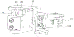
砂轮检测模块13包括设置在样片载台131两侧的旋转气缸132、设置在旋转气缸132上的电磁开关133、与旋转气缸132连接的挡板135,设置在旋转气缸132外侧的光纤探头134、以及邻近挡板135设置的清洁水管136,样片载台 131用于承载样片,电磁开关133控制旋转气缸132的开闭,旋转气缸132旋转带动挡板135旋转,需要利用光纤探头134进行砂轮检测时,挡板135旋转至垂直方向,露出光纤探头134,不需要使用光纤探头134时,挡板135将光纤探头 134遮挡以起到保护作用。清洁水管136可清洁砂轮磨削晶圆时附着在砂轮表面的硅粉,提高砂轮检测精度;光纤探头134设置有2个,本实施例中采用反射型光纤探头,1个水平设置提供水平方向的点光源,另一个垂直设置提供垂直方向的点光源;砂轮的位置包括高度和水平位置,水平点光源检测砂轮高度,测试过程中每次砂轮下降值高度不固定,砂轮高度由砂轮最低点确定,因此可以准确测试出砂轮的高度,补偿误差不高于2um,通过高度可计算砂轮的直径;垂直方向的点光源检测砂轮侧面的位置,从而确定砂轮在水平方向的位置;砂轮检测模块还可利用砂轮破损检测传感器137检测砂轮表面磨损情况,砂轮破损传感器137 设置在主轴电机403前端并靠近砂轮401的位置。The grinding
在线检测模块用于检测晶圆加工精度,确保晶圆加工质量可控。在线检测模块采用3D位移传感器检测晶圆的磨削深度和宽度。The online detection module is used to detect the wafer processing accuracy to ensure that the wafer processing quality is controllable. The online detection module uses a 3D displacement sensor to detect the grinding depth and width of the wafer.
转台模块5包括从上到下依次设置的顶升盘501、底座502、转接盘503和第二驱动电机504,顶升盘501和底座502通过连接件505连接。转接盘503与第二驱动电机504固定连接,第二驱动电机504驱动转接盘503旋转,带动底座 502和顶升盘501旋转,从而实现吸附在底座502上的晶圆旋转。在底座502上设置有顶升盘501和真空吸附槽506,转接盘503连接有旋转接头507,第一气路和第二气路通过旋转接头507分别与顶升盘501和真空吸附槽506连接,通过第一气路提供正压气源驱动顶升盘501上升使晶圆与吸附平台脱离,通过第二气路提供负压气源控制真空吸附槽506呈真空状态吸附晶圆,通过第三气路提供负压气源将底座502吸附在转接盘503上。The turntable module 5 includes a jacking
顶升盘501是晶圆卸料时的顶升机构,本发明的顶升盘501固定设置在底座 502上表面中央,两者通过至少3个连接件505相互连接,连接件505包括直线轴承551、连接导柱552、限位块553和弹簧554,连接导柱552套接在直线轴承551内并贯穿直线轴承551和限位块553,限位块设置在直线轴承551下端,连接导柱552上端与顶升盘501固定连接,连接导柱552底端设置限位凸台555,弹簧设置在限位块553与限位凸台555之间,直线轴承551固定在底座502内,连接件505下部向下伸入至设置在转接盘503上的圆柱槽56内。初始状态下,顶升盘501在弹簧554作用下与底座502贴合在一起,当第一气路通气时,产生正向的压力,顶升盘501在气压作用下克服弹簧力,整体上升。The lifting
在顶升盘501与底座502之间形成顶升布气区508,第一气路与顶升布气区 508连接。顶升布气区508由设置在顶升盘501底面的凸缘509与底座502围合而成,在底座502上设置有第一凹槽510,凸缘509嵌入第一凹槽510中,凸缘 509的高度小于第一凹槽510的深度,且大于顶升盘501升起的最高高度,凸缘 509与第一凹槽510之间设置有缝隙,可通过少量来自第一气路的正向压力的气体,防止水汽进入吸附平台内部。A jacking
在顶升布气区508上方顶升盘501上设置有若干出气孔512,出气孔512与顶升布气区508连接,在顶升盘501上表面出气孔512的外周设置有间隔分布的多根支撑条513,支撑条513之间留有间隙514。晶圆加工完成后,第二气路停止真空吸附,进行破真空,此时,第一气路导通提供正向的气源,正向气源将顶升盘501顶起一定高度;顶升盘501上升的同时极少部分气体从出气孔512流出,辅助晶圆破真空,同时该气流使顶升盘501与晶圆之间的残留水从间隙514流出,减少因水的表面张力带来的晶圆与顶升盘501不易分离的问题,进一步辅助晶圆破真空;另外,支撑条513的设置使晶圆与顶升盘501之间的接触面积小,该设置也有利于晶圆破真空。A number of air outlet holes 512 are arranged on the jacking
第一气路包括第一真空导柱511、以及设置在旋转接头507内的第一通道(图中未示出,为现有的旋转接头的通道),第一真空导柱511与旋转接头507内的第一通道连接,旋转接头507第一通道的两端分别为设置在固定部571上的第一微型接头572和设置在旋转部573上的第二微型接头574,第一微型接头572和第二微型接头574在旋转接头507内部连通,第一微型接头572通过管路与外部的供气设备连接,第二微型接头574与第一真空导柱511连接。第一微型接头 572、第一通道、第二微型接头574、第一真空导柱511依次联通形成第一气路,为顶升布气区508供气,提供给顶升盘501正向压力的气体,将顶升盘501向上顶起。The first gas path includes a first
为了使晶圆固定在吸附平台上,底座502整体采用陶瓷制成,在底座502 上顶升盘501的外周设置真空吸附槽506,或者底座502采用金属制成,在顶升盘501外周的底座502上设置陶瓷吸附盘23,真空吸附槽506开设在陶瓷吸附盘23上,第二气路与真空吸附槽506连接,通过第二气路使真空吸附槽506与晶圆之间形成负压状态,吸附晶圆。In order to fix the wafer on the adsorption platform, the
第二气路包括第二真空导柱515、设置在底座502上的若干气道516、以及设置在旋转接头507内的第二通道(图中未示出,为现有旋转接头的通道),第二真空导柱515一端通过接头与旋转接头507的第二通道连接,另一端与气道 516连接,气道516与真空吸附槽506连通。气道516径向均匀布设在底座502 内部并在底座502的中心相互连通,本发明的气道516设置为6条。The second air path includes a second
第二真空导柱515与旋转接头507内的第二通道连接,旋转接头507第二通道的两端分别为设置在固定部571上的第三微型接头575和设置在旋转部573 上的第四微型接头576,第三微型接头575和第四微型接头576在旋转接头507 内部连通,第三微型接头575通过管路与外部的抽真空设备连接,第四微型接头 576与第二真空导柱515连接。第三微型接头575、第二通道、第四微型接头576、第二真空导柱515依次联通形成第二气路,第二气路依次与气道516、真空吸附槽506连通,将真空吸附槽506与晶圆之前的空间抽真空,吸附晶圆。The second
在底座502上,位于真空吸附槽506与顶升盘501之间的位置设置有排水槽517,排水槽517连接有若干排水孔518。排水孔518贯穿底座502,一端连接排水槽517,另一端倾斜向下连通至底座502外部,进行排水。排水孔518设置有多个,均匀分布在底座502的圆周向上。On the
第三气路提供负压气源,用于转接盘503吸附底座502,在转接盘503上表面设置有若干相互连通的环形的第二凹槽521,底座502下表面紧贴第二凹槽 521,第二凹槽521通过开设在转接盘503上的竖向通孔522、第五微型接头577 与设置在旋转部573上的第六微型接头578连接,在固定部571上设置有第七微型接头579,第六微型接头578与第七微型接头579通过旋转接头507内部的第三通道连接。第七微型接头579、第三通道、第六微型接头578、第五微型接头 577、竖向通孔522形成第三气路,通过第三气路向第二凹槽521提供负压气源。在转接盘和底座之间还设置有若干定位销,防止底座502位置偏移。The third air circuit provides a negative pressure gas source for the
第二驱动电机504为直驱电机(DD马达),转接盘503与直驱电机固定连接,同时转接盘503与旋转接头507的旋转部573连接。第二驱动电机504驱动转接盘503旋转,带动底座502和顶升盘501旋转,从而实现吸附在底座502 和顶升盘501上的晶圆旋转。本发明采用DD马达为转台提供动力,DD马达直接连接到转接盘上,实现对转接盘的直接驱动,消除了由机械传动带来的反向间隙、柔度以及与之相关的其它问题,静音,精确度高,使用寿命长。The
转接盘503外周设置有挡水圈519,挡水圈519通过密封垫520与底座502 连接,挡水圈519与滑台防水罩16的挡水圈嵌套使用,起到密封作用,防止晶圆磨削过程中的水流进入吸附平台内部。
晶圆放置在底座上,DD马达带动底座502和顶升盘501旋转,第二气路向真空吸附槽506提供负压,利用吸力将晶圆固定。当完成晶圆加工后,第二气路停止提供负压,开始破真空,第一气路提供正向的气体压力至顶升布气区508,将顶升盘501顶起,形成一种类似于单作用气缸的机构形式,使晶圆与底座502 分离,同时极小部分气体从出气孔512进一步帮助破真空,本发明利用气体将顶升盘顶起一定的高度,以方便搬运完成加工的晶圆。The wafer is placed on the base, the DD motor drives the
转台模块5外周设置有滑台防水罩16,滑台防水罩16外周设置有集水槽17,集水槽17外侧设置有检测集水槽17内水位的液位传感器18,集水槽17收集磨削过程中产生的切削液、冷却液和清洗液,并根据液位传感器18检测的液位信息,将液体排出。The outer periphery of the turntable module 5 is provided with a sliding table
本发明的工作过程:晶圆到达预定位单元后,进行预定位,然后利用夹爪单元转移至转台;利用视觉检测模块进行定位检测,三轴联动将砂轮和晶圆移至磨削位置进行晶圆磨边;完成磨边工序后,转台模块回至装载位。在晶圆磨边工艺过程中,完成设定次数磨削工序后,需进行砂轮修整,利用砂轮检测模块和试切检测模块,进行砂轮检测和试切检测,检测砂轮实际直径和晶圆试切情况,确保砂轮精度。The working process of the present invention: After the wafer arrives at the pre-positioning unit, it is pre-positioned, and then transferred to the turntable by the gripper unit; the positioning detection is performed by the visual detection module, and the three-axis linkage moves the grinding wheel and the wafer to the grinding position for wafer grinding. Round edging; after finishing the edging process, the turntable module returns to the loading position. During the wafer edging process, after the set number of grinding processes are completed, the grinding wheel needs to be trimmed. Use the grinding wheel detection module and the trial cutting detection module to perform grinding wheel detection and trial cutting detection, and detect the actual diameter of the grinding wheel and the trial cutting of the wafer. situation, to ensure the accuracy of the grinding wheel.
以上仅是本发明的优选实施方式,应当指出,对于本技术领域的普通技术人员来说,在不脱离本发明原理的前提下,还可以做出若干改进和润饰,这些改进和润饰也应视为本发明的保护范围。The above are only preferred embodiments of the present invention, and it should be pointed out that for those of ordinary skill in the art, some improvements and modifications can also be made without departing from the principle of the present invention, and these improvements and modifications should also be considered Be the protection scope of the present invention.
Claims (8)
Priority Applications (1)
| Application Number | Priority Date | Filing Date | Title |
|---|---|---|---|
| CN202110232675.9A CN114454024B (en) | 2021-03-02 | 2021-03-02 | Wafer Processing Equipment |
Applications Claiming Priority (1)
| Application Number | Priority Date | Filing Date | Title |
|---|---|---|---|
| CN202110232675.9A CN114454024B (en) | 2021-03-02 | 2021-03-02 | Wafer Processing Equipment |
Publications (2)
| Publication Number | Publication Date |
|---|---|
| CN114454024A CN114454024A (en) | 2022-05-10 |
| CN114454024B true CN114454024B (en) | 2023-04-25 |
Family
ID=81405149
Family Applications (1)
| Application Number | Title | Priority Date | Filing Date |
|---|---|---|---|
| CN202110232675.9A Active CN114454024B (en) | 2021-03-02 | 2021-03-02 | Wafer Processing Equipment |
Country Status (1)
| Country | Link |
|---|---|
| CN (1) | CN114454024B (en) |
Families Citing this family (4)
| Publication number | Priority date | Publication date | Assignee | Title |
|---|---|---|---|---|
| CN116008596B (en) * | 2022-12-02 | 2023-11-28 | 苏州锐杰微科技集团有限公司 | FT detection device for circuit board and chip packaging technology |
| CN117001188A (en) * | 2023-07-26 | 2023-11-07 | 北京中科镭特电子有限公司 | Wafer laser dicing method, dicing system, process equipment and readable storage medium |
| CN117207027B (en) * | 2023-10-27 | 2024-08-20 | 浙江振兴阿祥集团有限公司 | Grooving machine for processing solar silicon wafer storage rack body |
| CN118841344B (en) * | 2024-06-24 | 2025-06-10 | 北京芯力技术创新中心有限公司 | Wafer trimming machine and wafer trimming method |
Citations (7)
| Publication number | Priority date | Publication date | Assignee | Title |
|---|---|---|---|---|
| TW200905788A (en) * | 2007-06-12 | 2009-02-01 | Nikon Corp | Substrate detecting apparatus, substrate aligning apparatus, substrate bonding apparatus having substrate detecting apparatus and substrate aligning apparatus, wafer outer shape detecting apparatus, wafer aligning apparatus, and wafer bonding apparat |
| CN108527010A (en) * | 2017-03-06 | 2018-09-14 | 株式会社荏原制作所 | Grinding method, grinding device, base plate processing system and recording medium |
| CN110405603A (en) * | 2019-08-19 | 2019-11-05 | 安吉圆磨机械科技有限公司 | A dedicated shaping machine for silicon carbide crystals |
| CN110421486A (en) * | 2019-07-23 | 2019-11-08 | 郑州磨料磨具磨削研究所有限公司 | A kind of trimming device and method that channel grinding abrasive disk profile detects automatically and regulates and controls |
| CN110744386A (en) * | 2019-09-17 | 2020-02-04 | 西北电子装备技术研究所(中国电子科技集团公司第二研究所) | Profile grinding chamfering machine for special-shaped wafer |
| JP2020028927A (en) * | 2018-08-21 | 2020-02-27 | 株式会社荏原製作所 | Polishing device and polishing method |
| CN110970322A (en) * | 2018-09-30 | 2020-04-07 | 上海微电子装备(集团)股份有限公司 | A chip mounting device and a chip mounting method |
Family Cites Families (1)
| Publication number | Priority date | Publication date | Assignee | Title |
|---|---|---|---|---|
| JP6792363B2 (en) * | 2016-07-22 | 2020-11-25 | 株式会社ディスコ | Grinding device |
-
2021
- 2021-03-02 CN CN202110232675.9A patent/CN114454024B/en active Active
Patent Citations (7)
| Publication number | Priority date | Publication date | Assignee | Title |
|---|---|---|---|---|
| TW200905788A (en) * | 2007-06-12 | 2009-02-01 | Nikon Corp | Substrate detecting apparatus, substrate aligning apparatus, substrate bonding apparatus having substrate detecting apparatus and substrate aligning apparatus, wafer outer shape detecting apparatus, wafer aligning apparatus, and wafer bonding apparat |
| CN108527010A (en) * | 2017-03-06 | 2018-09-14 | 株式会社荏原制作所 | Grinding method, grinding device, base plate processing system and recording medium |
| JP2020028927A (en) * | 2018-08-21 | 2020-02-27 | 株式会社荏原製作所 | Polishing device and polishing method |
| CN110970322A (en) * | 2018-09-30 | 2020-04-07 | 上海微电子装备(集团)股份有限公司 | A chip mounting device and a chip mounting method |
| CN110421486A (en) * | 2019-07-23 | 2019-11-08 | 郑州磨料磨具磨削研究所有限公司 | A kind of trimming device and method that channel grinding abrasive disk profile detects automatically and regulates and controls |
| CN110405603A (en) * | 2019-08-19 | 2019-11-05 | 安吉圆磨机械科技有限公司 | A dedicated shaping machine for silicon carbide crystals |
| CN110744386A (en) * | 2019-09-17 | 2020-02-04 | 西北电子装备技术研究所(中国电子科技集团公司第二研究所) | Profile grinding chamfering machine for special-shaped wafer |
Also Published As
| Publication number | Publication date |
|---|---|
| CN114454024A (en) | 2022-05-10 |
Similar Documents
| Publication | Publication Date | Title |
|---|---|---|
| CN114454024B (en) | Wafer Processing Equipment | |
| CN102554760B (en) | A multifunctional substrate grinding and polishing device and grinding and polishing method thereof | |
| CN106475878B (en) | A kind of full-automatic silicon single crystal rod barreling integrated equipment | |
| CN109014959B (en) | A pump casing production line | |
| CN112775625B (en) | On-site processing technology and processing device of a large flange | |
| CN115338717A (en) | Wafer thinning equipment | |
| CN102371434A (en) | Laser processing method and laser processing apparatus | |
| CN208358526U (en) | Planetary polishing device and lower module base | |
| CN102161168A (en) | Small-caliber aspherical composite precise processing machine tool | |
| CN219626614U (en) | Bearing mechanism | |
| CN106166712A (en) | On-line grinding and detection integral system | |
| CN110039424A (en) | A kind of industrialization workpiece producing unit | |
| CN115752259A (en) | Measuring equipment for planet carrier of ultrahigh-precision RV reducer | |
| CN116372760A (en) | High-precision numerical control grinding machine and working method thereof | |
| WO2024178862A1 (en) | Carrier disc positioning device of multi-column high-precision polisher | |
| CN208788258U (en) | Burnishing device and polished die group | |
| CN217007403U (en) | Mask and wafer detection clamp | |
| CN115488067A (en) | Biax high efficiency detects semiconductor wafer cutter | |
| CN115139205A (en) | Finishing impression polishing all-in-one | |
| CN116190301B (en) | Wafer defect detection device and wafer loading system | |
| CN220761920U (en) | Nuclear power valve intelligent polishing detection system | |
| CN118106873A (en) | A high-rigidity five-axis linkage ultra-precision grinding machine tool | |
| CN220200410U (en) | Turntable sinking type station | |
| CN201233433Y (en) | Full automatic testing and discriminating gear for wafer of each specification | |
| CN101261307A (en) | Full-automatic each specification wafer test and discriminating device |
Legal Events
| Date | Code | Title | Description |
|---|---|---|---|
| PB01 | Publication | ||
| PB01 | Publication | ||
| SE01 | Entry into force of request for substantive examination | ||
| SE01 | Entry into force of request for substantive examination | ||
| GR01 | Patent grant | ||
| GR01 | Patent grant |