CN113531081A - Hydraulic coupler based on magnetorheological fluid - Google Patents
Hydraulic coupler based on magnetorheological fluid Download PDFInfo
- Publication number
- CN113531081A CN113531081A CN202110728857.5A CN202110728857A CN113531081A CN 113531081 A CN113531081 A CN 113531081A CN 202110728857 A CN202110728857 A CN 202110728857A CN 113531081 A CN113531081 A CN 113531081A
- Authority
- CN
- China
- Prior art keywords
- transmission
- hydraulic coupler
- main shaft
- magnetorheological fluid
- telescopic baffle
- Prior art date
- Legal status (The legal status is an assumption and is not a legal conclusion. Google has not performed a legal analysis and makes no representation as to the accuracy of the status listed.)
- Granted
Links
- 239000012530 fluid Substances 0.000 title claims abstract description 30
- 230000005540 biological transmission Effects 0.000 claims abstract description 77
- 238000007789 sealing Methods 0.000 claims abstract description 24
- 125000006850 spacer group Chemical group 0.000 claims abstract description 11
- 230000008878 coupling Effects 0.000 claims description 9
- 238000010168 coupling process Methods 0.000 claims description 9
- 238000005859 coupling reaction Methods 0.000 claims description 9
- 239000007788 liquid Substances 0.000 abstract description 13
- 230000009471 action Effects 0.000 description 7
- 238000000034 method Methods 0.000 description 7
- 230000008569 process Effects 0.000 description 4
- 238000010008 shearing Methods 0.000 description 2
- 230000004075 alteration Effects 0.000 description 1
- 230000009286 beneficial effect Effects 0.000 description 1
- 230000000694 effects Effects 0.000 description 1
- 230000004048 modification Effects 0.000 description 1
- 238000012986 modification Methods 0.000 description 1
- 230000001105 regulatory effect Effects 0.000 description 1
- 238000006467 substitution reaction Methods 0.000 description 1
Images


Classifications
-
- F—MECHANICAL ENGINEERING; LIGHTING; HEATING; WEAPONS; BLASTING
- F16—ENGINEERING ELEMENTS AND UNITS; GENERAL MEASURES FOR PRODUCING AND MAINTAINING EFFECTIVE FUNCTIONING OF MACHINES OR INSTALLATIONS; THERMAL INSULATION IN GENERAL
- F16H—GEARING
- F16H41/00—Rotary fluid gearing of the hydrokinetic type
- F16H41/24—Details
-
- F—MECHANICAL ENGINEERING; LIGHTING; HEATING; WEAPONS; BLASTING
- F16—ENGINEERING ELEMENTS AND UNITS; GENERAL MEASURES FOR PRODUCING AND MAINTAINING EFFECTIVE FUNCTIONING OF MACHINES OR INSTALLATIONS; THERMAL INSULATION IN GENERAL
- F16H—GEARING
- F16H41/00—Rotary fluid gearing of the hydrokinetic type
- F16H41/32—Selection of working fluids
Landscapes
- Engineering & Computer Science (AREA)
- General Engineering & Computer Science (AREA)
- Mechanical Engineering (AREA)
- Dynamo-Electric Clutches, Dynamo-Electric Brakes (AREA)
Abstract
The invention relates to the technical field of hydraulic coupler transmission equipment, and discloses a hydraulic coupler based on magnetorheological fluid, which comprises a transmission main shaft, wherein a sealing spacer bush is fixedly sleeved in the middle of the outer surface of the transmission main shaft, a movable snap ring is movably sleeved on the outer surface of the sealing spacer bush, a transmission block is fixedly sleeved on one side of the outer surface of the transmission main shaft, and a telescopic baffle is movably connected inside the transmission block. The hydraulic coupler based on the magnetorheological fluid has the advantages that the movable clamping ring and the telescopic baffle are arranged on the transmission main shaft, so that when the hydraulic coupler transmits different torques, the extending length of the telescopic baffle is adjusted by the movable clamping ring, the telescopic baffle and a flowing liquid transmission medium form an included angle of 90 degrees, the kinetic energy loss of the liquid transmission medium in the transmission process is effectively reduced, the hydraulic coupler is not easy to slip when transmitting larger torque or smaller torque, and the stability and the reliability are high.
Description
Technical Field
The invention relates to the technical field of hydraulic coupler transmission equipment, in particular to a hydraulic coupler based on magnetorheological fluid.
Background
The hydraulic coupler is a device which uses liquid as working medium to implement power transmission between prime mover and working machine, and is mainly formed from shell body, pump wheel, turbine and scoop tube, etc., and the lifting of scoop tube can be used for regulating oil filling quantity of working cavity of hydraulic coupler, and can further regulate output torque of turbine, and can regulate rotating speed of output shaft of prime mover under the condition of that its rotating speed is not changed.
The prior hydraulic coupler utilizes the scoop tube to control the oil filling amount of the liquid medium so as to control the transmission torque of the hydraulic coupler, most of the power of the hydraulic coupler is consumed by the rotating shear of the turbine blades due to the influence of the shear force of the turbine blades, and the adjustable range of the torque of the hydraulic coupler is greatly limited, so that the hydraulic coupler is easy to slip when transmitting larger torque or smaller torque, and has poor stability and reliability.
Therefore, a hydraulic coupling is needed to solve the above-mentioned drawbacks of the conventional hydraulic coupling.
Disclosure of Invention
Technical problem to be solved
The invention provides a hydraulic coupler based on magnetorheological fluid, which has the advantages of adjusting the deflection angle of a turbine blade according to the transmitted torque, changing the viscosity of a liquid medium, reducing the power consumption of the turbine blade on the liquid medium during rotation, effectively improving the size range, stability and reliability of the hydraulic coupler on torque transmission, solving the problems that the prior hydraulic coupler utilizes a scoop tube to control the oil filling amount of the liquid medium so as to control the transmitted torque of the hydraulic coupler, most of the power of the hydraulic coupler is consumed by the rotating shearing of the turbine blade due to the influence of the shearing force of the turbine blade, and further the adjustable range of the torque of the hydraulic coupler is greatly limited, and the hydraulic coupler is easy to slip when transmitting larger torque or smaller torque, poor stability and reliability.
(II) technical scheme
The invention provides the following technical scheme: a hydraulic coupler based on magnetorheological fluid comprises a transmission main shaft, wherein a sealing spacer bush is fixedly sleeved in the middle of the outer surface of the transmission main shaft, the outer surface of the sealing spacer sleeve is movably sleeved with a movable snap ring, one side of the outer surface of the transmission main shaft is fixedly sleeved with a transmission block, one end of the sealing spacer bush is contacted with one side of the transmission block, the interior of the transmission block is movably connected with a telescopic baffle, one side of the telescopic baffle is in meshing transmission with the inside of the movable snap ring, one side of the outer surface of the movable snap ring is movably sleeved with the sealing baffle, one side of the outer surface of the transmission main shaft is movably sleeved with the driven connecting plate, and an electromagnetic coil is fixedly installed on the outer surface of the driven connecting plate, the outer surface of the sealing baffle plate is contacted with the inner wall of the electromagnetic coil, and a driven connecting shaft is fixedly installed on one side of the driven connecting plate through a transmission support.
Preferably, the chamber formed by the sealing baffle, the driven connecting plate and the electromagnetic coil is filled with full-volume magnetorheological fluid.
Preferably, the outer part of the telescopic baffle is a plate-shaped structure with column-shaped protrusions at the front side and the rear side, and the top end of the telescopic baffle is an arc-shaped curved surface structure with the same radian of the outer surface of the transmission block.
Preferably, the distance between the driven connecting plate and the sealing baffle is equal to the thickness of the transmission block, and the outer surface of the movable snap ring is provided with an inner hexagonal structure groove hole in an annular array.
(III) advantageous effects
The invention has the following beneficial effects:
1. the hydraulic coupler based on the magnetorheological fluid has the advantages that the movable clamping ring and the telescopic baffle are arranged on the transmission main shaft, so that when the hydraulic coupler transmits different torques, the extending length of the telescopic baffle is adjusted by the movable clamping ring, the telescopic baffle and a flowing liquid transmission medium form an included angle of 90 degrees, the kinetic energy loss of the liquid transmission medium in the transmission process is effectively reduced, the hydraulic coupler is not easy to slip when transmitting larger torque or smaller torque, and the stability and the reliability are high.
2. The magnetorheological fluid-based hydraulic coupler is provided with the sealing baffle, the driven connecting plate and the magnetorheological fluid in the inner cavity of the electromagnetic coil, and different magnetic fields are applied to the magnetorheological fluid through the electromagnetic coil, so that the viscosity of the magnetorheological fluid is changed, the transmission of the hydraulic coupler to torque is further improved, the phenomenon that the hydraulic coupler is not easy to slip in the torque transmission process is ensured, and the stability and the reliability of the hydraulic coupler in the operation process are further improved.
Drawings
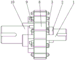
FIG. 1 is a schematic structural view of the present invention;
FIG. 2 is a front view of the structure of the present invention;
FIG. 3 is a schematic view of the drive spindle of the present invention and the structure thereon;
fig. 4 is a schematic view of the driven connecting shaft and the structure thereon.
In the figure: 1. a transmission main shaft; 2. sealing the spacer bush; 3. a movable snap ring; 4. a transmission block; 5. a telescopic baffle; 6. sealing the baffle; 7. a driven connecting plate; 8. an electromagnetic coil; 9. a transmission bracket; 10. the driven is connected with the shaft.
Detailed Description
The technical solutions in the embodiments of the present invention will be clearly and completely described below with reference to the drawings in the embodiments of the present invention, and it is obvious that the described embodiments are only a part of the embodiments of the present invention, and not all of the embodiments. All other embodiments, which can be derived by a person skilled in the art from the embodiments given herein without making any creative effort, shall fall within the protection scope of the present invention.
Referring to fig. 1-4, a fluid coupling based on magnetorheological fluid comprises a transmission main shaft 1, a seal spacer 2 fixedly sleeved in the middle of the outer surface of the transmission main shaft 1, a movable snap ring 3 movably sleeved on the outer surface of the seal spacer 2, a transmission block 4 fixedly sleeved on one side of the outer surface of the transmission main shaft 1, one end of the sealing spacer bush 2 is contacted with one side of the transmission block 4, the interior of the transmission block 4 is movably connected with a telescopic baffle 5, one side of the telescopic baffle 5 is engaged with the inside of the movable snap ring 3 for transmission, one side of the outer surface of the movable snap ring 3 is movably sleeved with a sealing baffle 6, one side of the outer surface of the transmission main shaft 1 is movably sleeved with a driven connecting plate 7, and the outer surface of the driven connecting plate 7 is fixedly provided with an electromagnetic coil 8, the outer surface of the sealing baffle 6 is contacted with the inner wall of the electromagnetic coil 8, and one side of the driven connecting plate 7 is fixedly provided with a driven connecting shaft 10 through a transmission bracket 9.
The arrangement of the mounting structure on the transmission main shaft 1 and the mounting structure on the driven connecting shaft 10 forms a group of flexibly connected transmission components between the transmission main shaft 1 and the driven connecting shaft 10, thereby realizing the transmission of power.
The arrangement of the movable snap ring 3 and the telescopic baffle 5 on the transmission main shaft 1 is convenient for adjusting the extending length of the telescopic baffle 5 by utilizing the movable snap ring 3 when the hydraulic coupler transmits different torques, and the telescopic baffle 5 and a flowing liquid transmission medium form an included angle of 90 degrees, so that the kinetic energy loss of the liquid transmission medium in the transmission process is effectively reduced, the phenomenon of slippage of the hydraulic coupler is avoided when the hydraulic coupler transmits larger torque or smaller torque, and the stability and the reliability are high.
In the technical scheme, a chamber formed by the sealing baffle 6, the driven connecting plate 7 and the electromagnetic coil 8 is filled with full-volume magnetorheological fluid.
The magnetorheological fluid is arranged in the inner cavities of the sealing baffle 6, the driven connecting plate 7 and the electromagnetic coil 8, different magnetic fields are applied to the magnetorheological fluid through the electromagnetic coil 8, the viscosity of the magnetorheological fluid is changed, the torque transmission of the hydraulic coupler is further improved, the phenomenon that the hydraulic coupler is not easy to slip in the torque transmission process is ensured, and the stability and the reliability of the hydraulic coupler in the operation process are further improved.
In this technical scheme, the outside of telescopic baffle 5 is established to the bellied platelike structure of both sides post type around, and its top is established to the same arc curved surface structure of the surface radian of transmission block 4.
The arrangement of the external structure of the telescopic baffle 5 can effectively reduce the impact force generated by the liquid transmission medium when the telescopic baffle rotates at a high speed while not influencing the contact effective contact area of the telescopic baffle and the liquid medium, thereby effectively reducing the vibration influence and noise pollution generated by the hydraulic coupling when the hydraulic coupling transmits power.
In the technical scheme, the distance between the driven connecting plate 7 and the sealing baffle 6 is equal to the thickness of the transmission block 4, and the outer surface of the movable snap ring 3 is provided with an inner hexagonal structure groove hole in an annular array.
Wherein, the arrangement of the inner hexagonal slotted hole on the movable snap ring 3 is convenient for adjusting the extension length of the telescopic baffle 5 by rotating the movable snap ring 3.
The use method and the working principle of the embodiment are as follows:
firstly, a transmission main shaft 1 is in transmission connection with a prime motor, a driven connecting shaft 10 is in transmission connection with a driven shaft and a transmission shaft, then a hexagon wrench is utilized to rotate a movable snap ring 3 according to the magnitude of required transmission torque, under the action of meshing transmission of gears, a telescopic baffle 5 is driven to contract inwards or expand outwards at a proper position, then an electromagnetic coil 8 and an electric feedback connection system and a circuit system of a control system are switched on, then the prime motor is started to drive a transmission block 4 and the telescopic baffle 5 on the prime motor to rotate along with the transmission action of the transmission main shaft 1, the magnitude of current led to the electromagnetic coil 8 is adjusted under the action of the control system, so that magnetic fields with different magnitudes are applied to the hydraulic coupler, the rheological fluid in an inner cavity of the hydraulic coupler is adjusted, and then the driven connecting plate 7 and the electromagnetic coil 8 on the driven connecting plate are driven under the action of the telescopic baffle 5, The driven connecting shaft 10 rotates at different speeds, when the transmission torque of the hydraulic coupler needs to be changed, the adjustment of the transmission torque of the hydraulic coupler can be completed only by changing the current led to the electromagnetic coil 8, and meanwhile, the extending length of the telescopic baffle 5 is matched with the viscosity of the magnetorheological fluid, so that the hydraulic coupler is not easy to slip when transmitting large torque or small torque, and the stability and the reliability are high.
It is noted that, herein, relational terms such as first and second, and the like may be used solely to distinguish one entity or action from another entity or action without necessarily requiring or implying any actual such relationship or order between such entities or actions. Also, the terms "comprises," "comprising," or any other variation thereof, are intended to cover a non-exclusive inclusion, such that a process, method, article, or apparatus that comprises a list of elements does not include only those elements but may include other elements not expressly listed or inherent to such process, method, article, or apparatus.
Although embodiments of the present invention have been shown and described, it will be appreciated by those skilled in the art that changes, modifications, substitutions and alterations can be made in these embodiments without departing from the principles and spirit of the invention, the scope of which is defined in the appended claims and their equivalents.
Claims (4)
1. A fluid coupling based on magnetorheological fluid comprises a transmission main shaft (1), and is characterized in that: the middle part of the outer surface of the transmission main shaft (1) is fixedly sleeved with a sealing spacer bush (2), a movable snap ring (3) is movably sleeved on the outer surface of the sealing spacer sleeve (2), a transmission block (4) is fixedly sleeved on one side of the outer surface of the transmission main shaft (1), a telescopic baffle (5) is movably connected inside the transmission block (4), one side of the telescopic baffle (5) is engaged with the inner part of the movable snap ring (3) for transmission, one side of the outer surface of the movable snap ring (3) is movably sleeved with a sealing baffle (6), one side of the outer surface of the transmission main shaft (1) is movably sleeved with a driven connecting plate (7), and the outer surface of the driven connecting plate (7) is fixedly provided with an electromagnetic coil (8), the outer surface of the sealing baffle plate (6) is contacted with the inner wall of the electromagnetic coil (8), one side of the driven connecting plate (7) is fixedly provided with a driven connecting shaft (10) through a transmission bracket (9).
2. A fluid coupling based on magnetorheological fluid according to claim 1, wherein: and a chamber consisting of the sealing baffle (6), the driven connecting plate (7) and the electromagnetic coil (8) is filled with magnetorheological fluid with full volume.
3. A fluid coupling based on magnetorheological fluid according to claim 2, wherein: the outside of the telescopic baffle (5) is set to be a plate-shaped structure with column-shaped protrusions at the front side and the rear side, and the top end of the telescopic baffle is set to be an arc-shaped curved surface structure with the same radian of the outer surface of the transmission block (4).
4. A fluid coupling based on magnetorheological fluid according to claim 1, wherein: the distance between the driven connecting plate (7) and the sealing baffle (6) is equal to the thickness of the transmission block (4), and the outer surface of the movable snap ring (3) is provided with inner hexagonal structure slotted holes in an annular array.
Priority Applications (1)
| Application Number | Priority Date | Filing Date | Title |
|---|---|---|---|
| CN202110728857.5A CN113531081B (en) | 2021-06-29 | 2021-06-29 | Hydraulic coupler based on magnetorheological fluid |
Applications Claiming Priority (1)
| Application Number | Priority Date | Filing Date | Title |
|---|---|---|---|
| CN202110728857.5A CN113531081B (en) | 2021-06-29 | 2021-06-29 | Hydraulic coupler based on magnetorheological fluid |
Publications (2)
| Publication Number | Publication Date |
|---|---|
| CN113531081A true CN113531081A (en) | 2021-10-22 |
| CN113531081B CN113531081B (en) | 2022-12-23 |
Family
ID=78126209
Family Applications (1)
| Application Number | Title | Priority Date | Filing Date |
|---|---|---|---|
| CN202110728857.5A Active CN113531081B (en) | 2021-06-29 | 2021-06-29 | Hydraulic coupler based on magnetorheological fluid |
Country Status (1)
| Country | Link |
|---|---|
| CN (1) | CN113531081B (en) |
Citations (21)
| Publication number | Priority date | Publication date | Assignee | Title |
|---|---|---|---|---|
| EP0909901A1 (en) * | 1997-10-17 | 1999-04-21 | Eaton Corporation | Magneto rheological fluid coupling |
| WO2003054417A2 (en) * | 2001-11-08 | 2003-07-03 | Satcon Technology Corporation | Continuously variable transmissions using magnetorheological fluid or oil shear and methods of and systems for using the same in a vehicle, in-wheel application |
| CN101029664A (en) * | 2007-04-02 | 2007-09-05 | 中国矿业大学 | Magnetic rheological hydraulic flexible starter |
| ATE377162T1 (en) * | 2002-10-31 | 2007-11-15 | Magna Drivetrain Ag & Co Kg | MAGNETORHEOLOGICAL COUPLING |
| CA2574453A1 (en) * | 2007-01-15 | 2008-07-15 | David Kadlec | Magneto-rheological camera motion, support, and positioning device |
| CN101718314A (en) * | 2010-02-08 | 2010-06-02 | 中国矿业大学 | Spherical magnetorheological fluid clutch |
| CN101915277A (en) * | 2010-07-21 | 2010-12-15 | 河海大学 | A single-plate three-disc magneto-rheological clutch |
| DE102009034055A1 (en) * | 2009-07-21 | 2011-01-27 | Fraunhofer-Gesellschaft zur Förderung der angewandten Forschung e.V. | Torque-limited coupling element and method for torque-limited coupling |
| CN102562979A (en) * | 2012-01-19 | 2012-07-11 | 中国矿业大学 | Magnetorheological fluid transmission device with variable power |
| US20130175132A1 (en) * | 2010-09-15 | 2013-07-11 | Inventus Engineering Gmbh | Magnetorheological transmission device |
| CN103963556A (en) * | 2014-04-30 | 2014-08-06 | 占舒婷 | Deformable wheel |
| CN104019153A (en) * | 2014-06-11 | 2014-09-03 | 浙江师范大学 | Communication magnetorheological fluid clutch |
| US20140265316A1 (en) * | 2013-03-15 | 2014-09-18 | Kevin Mullin | Locking catch and latch for quick connect hydraulic coupler |
| CN108506367A (en) * | 2018-04-11 | 2018-09-07 | 陈学琴 | Flexible controllable clutch |
| WO2019052072A1 (en) * | 2017-09-14 | 2019-03-21 | 合肥工业大学 | Brake using magnetorheological transmission and brake-by-wire |
| CN109538649A (en) * | 2018-12-05 | 2019-03-29 | 吉林大学 | A kind of axially movable squash type multi-layer cylinder clutch based on magnetic rheological liquid |
| US20190390721A1 (en) * | 2018-06-21 | 2019-12-26 | National Tsing Hua University | Magnetorheological fluid clutch and operation method thereof |
| CN110792745A (en) * | 2019-12-02 | 2020-02-14 | 江苏科技大学 | Hydraulic torque converter |
| CN111765180A (en) * | 2020-06-04 | 2020-10-13 | 黄剑 | A transmission coupling mechanism based on magnetorheological fluid |
| CN111911565A (en) * | 2020-06-08 | 2020-11-10 | 许飚 | Spindle braking mechanism based on magnetorheological fluid |
| CN112855882A (en) * | 2021-01-19 | 2021-05-28 | 孙瑜辰 | Stepless speed change mechanism based on electrorheological fluid |
-
2021
- 2021-06-29 CN CN202110728857.5A patent/CN113531081B/en active Active
Patent Citations (22)
| Publication number | Priority date | Publication date | Assignee | Title |
|---|---|---|---|---|
| EP0909901A1 (en) * | 1997-10-17 | 1999-04-21 | Eaton Corporation | Magneto rheological fluid coupling |
| CN1226645A (en) * | 1997-10-17 | 1999-08-25 | 易通公司 | Improved magneto-rheological fluid coupling |
| WO2003054417A2 (en) * | 2001-11-08 | 2003-07-03 | Satcon Technology Corporation | Continuously variable transmissions using magnetorheological fluid or oil shear and methods of and systems for using the same in a vehicle, in-wheel application |
| ATE377162T1 (en) * | 2002-10-31 | 2007-11-15 | Magna Drivetrain Ag & Co Kg | MAGNETORHEOLOGICAL COUPLING |
| CA2574453A1 (en) * | 2007-01-15 | 2008-07-15 | David Kadlec | Magneto-rheological camera motion, support, and positioning device |
| CN101029664A (en) * | 2007-04-02 | 2007-09-05 | 中国矿业大学 | Magnetic rheological hydraulic flexible starter |
| DE102009034055A1 (en) * | 2009-07-21 | 2011-01-27 | Fraunhofer-Gesellschaft zur Förderung der angewandten Forschung e.V. | Torque-limited coupling element and method for torque-limited coupling |
| CN101718314A (en) * | 2010-02-08 | 2010-06-02 | 中国矿业大学 | Spherical magnetorheological fluid clutch |
| CN101915277A (en) * | 2010-07-21 | 2010-12-15 | 河海大学 | A single-plate three-disc magneto-rheological clutch |
| US20130175132A1 (en) * | 2010-09-15 | 2013-07-11 | Inventus Engineering Gmbh | Magnetorheological transmission device |
| CN102562979A (en) * | 2012-01-19 | 2012-07-11 | 中国矿业大学 | Magnetorheological fluid transmission device with variable power |
| US20140265316A1 (en) * | 2013-03-15 | 2014-09-18 | Kevin Mullin | Locking catch and latch for quick connect hydraulic coupler |
| CN103963556A (en) * | 2014-04-30 | 2014-08-06 | 占舒婷 | Deformable wheel |
| CN104019153A (en) * | 2014-06-11 | 2014-09-03 | 浙江师范大学 | Communication magnetorheological fluid clutch |
| WO2019052072A1 (en) * | 2017-09-14 | 2019-03-21 | 合肥工业大学 | Brake using magnetorheological transmission and brake-by-wire |
| CN108506367A (en) * | 2018-04-11 | 2018-09-07 | 陈学琴 | Flexible controllable clutch |
| US20190390721A1 (en) * | 2018-06-21 | 2019-12-26 | National Tsing Hua University | Magnetorheological fluid clutch and operation method thereof |
| CN109538649A (en) * | 2018-12-05 | 2019-03-29 | 吉林大学 | A kind of axially movable squash type multi-layer cylinder clutch based on magnetic rheological liquid |
| CN110792745A (en) * | 2019-12-02 | 2020-02-14 | 江苏科技大学 | Hydraulic torque converter |
| CN111765180A (en) * | 2020-06-04 | 2020-10-13 | 黄剑 | A transmission coupling mechanism based on magnetorheological fluid |
| CN111911565A (en) * | 2020-06-08 | 2020-11-10 | 许飚 | Spindle braking mechanism based on magnetorheological fluid |
| CN112855882A (en) * | 2021-01-19 | 2021-05-28 | 孙瑜辰 | Stepless speed change mechanism based on electrorheological fluid |
Non-Patent Citations (5)
| Title |
|---|
| 张春光等: "磁流变液软启动装置的设计", 《机械传动》 * |
| 徐熙: "CO46型液力偶合器调速机构的改进设想", 《华东电力》 * |
| 鲁光涛等: "基于宾汉模型的磁流变液联轴器工作转矩预测", 《磁性材料及器件》 * |
| 麻建坐等: "圆筒式磁流变离合器传动特性分析", 《重庆工学院学报(自然科学版)》 * |
| 黄家海: "液粘调速离合器流体剪切传动机理研究", 《中国博士学位论文全文数据库电子期刊工程科技Ⅱ辑》 * |
Also Published As
| Publication number | Publication date |
|---|---|
| CN113531081B (en) | 2022-12-23 |
Similar Documents
| Publication | Publication Date | Title |
|---|---|---|
| CN101694149B (en) | Deep well drilling speed reducer and working method thereof | |
| CN202510584U (en) | Cylindrical magnetorheological fluid coupling | |
| CN101927948B (en) | Driving device and driving mechanism of guide plate of moving double-box electric lifting appliance of container | |
| CN101392822B (en) | Hydraulic synchronization transmission | |
| CN101701611B (en) | Breakdown torque coupler | |
| CN103206507A (en) | Motive power and fluid power driving device based on motor and torque converter integration unit | |
| CN110259565A (en) | A kind of silicon oil filled fan clutch assembly structure | |
| CN113531081A (en) | Hydraulic coupler based on magnetorheological fluid | |
| CN114934963A (en) | Hollow cylinder type magnetorheological fluid transmission device | |
| CN208619552U (en) | A new type of magnetorheological clutch with annular gap | |
| CN210315541U (en) | Eccentric moment adjusting device of vibration hammer gear box | |
| CN202014191U (en) | Permanent magnet coupling | |
| CN101789730B (en) | A kind of motor soft start device based on magnetorheological grease | |
| CN109812557B (en) | Spoon pipe device for hydraulic coupler | |
| CN208203847U (en) | flexible speed change clutch soft start transmission device | |
| CN201546614U (en) | Deep well drilling speed reducer | |
| CN112855882B (en) | Stepless speed change mechanism based on electrorheological fluid | |
| CN110005772B (en) | Permanent magnet type magnetorheological fluid transmission device | |
| CN115654054A (en) | A magneto-rheological fluid damper with heat dissipation function | |
| CN203654285U (en) | Vibratory hammer pile machine eccentric device | |
| CN208804140U (en) | Electric loader motor and transmission input shaft power drive mechanism | |
| CN202381643U (en) | Overload protection device of mixer | |
| CN105478921A (en) | Power deburring mechanism for hydraulic motor | |
| CN220950928U (en) | Gantry crane lifting permanent magnet gear driving system | |
| CN108223615A (en) | flexible speed change clutch soft start transmission device |
Legal Events
| Date | Code | Title | Description |
|---|---|---|---|
| PB01 | Publication | ||
| PB01 | Publication | ||
| SE01 | Entry into force of request for substantive examination | ||
| SE01 | Entry into force of request for substantive examination | ||
| TA01 | Transfer of patent application right |
Effective date of registration: 20221206 Address after: 320 Zhening East Road, Lishui Economic Development Zone, Nanjing, Jiangsu 210,000 Applicant after: VMTT INDUSTRY CO.,LTD. Address before: 150000 northeast Fangzi yitun, Chang'an village, Longquan Town, Bayan, Harbin City, Heilongjiang Province Applicant before: Fan Jinlai |
|
| TA01 | Transfer of patent application right | ||
| GR01 | Patent grant | ||
| GR01 | Patent grant |