CN112526458B - Broadband NLFM (non-line-of-sight) emission beam forming method based on parameter fraction time delay extraction - Google Patents
Broadband NLFM (non-line-of-sight) emission beam forming method based on parameter fraction time delay extraction Download PDFInfo
- Publication number
- CN112526458B CN112526458B CN202011355255.1A CN202011355255A CN112526458B CN 112526458 B CN112526458 B CN 112526458B CN 202011355255 A CN202011355255 A CN 202011355255A CN 112526458 B CN112526458 B CN 112526458B
- Authority
- CN
- China
- Prior art keywords
- phase
- time delay
- delay
- array element
- signal
- Prior art date
- Legal status (The legal status is an assumption and is not a legal conclusion. Google has not performed a legal analysis and makes no representation as to the accuracy of the status listed.)
- Active
Links
- 238000000034 method Methods 0.000 title claims abstract description 43
- 238000000605 extraction Methods 0.000 title claims abstract description 7
- 238000012545 processing Methods 0.000 claims abstract description 24
- 238000005070 sampling Methods 0.000 claims description 22
- 230000005540 biological transmission Effects 0.000 claims description 12
- 238000001228 spectrum Methods 0.000 claims description 12
- 230000010363 phase shift Effects 0.000 claims description 11
- 230000008569 process Effects 0.000 claims description 9
- 230000003111 delayed effect Effects 0.000 claims description 7
- 230000001934 delay Effects 0.000 claims description 4
- 239000002131 composite material Substances 0.000 claims description 3
- 230000010354 integration Effects 0.000 claims description 3
- 230000035485 pulse pressure Effects 0.000 abstract description 5
- 238000004088 simulation Methods 0.000 description 13
- 230000006835 compression Effects 0.000 description 8
- 238000007906 compression Methods 0.000 description 8
- 238000010586 diagram Methods 0.000 description 8
- 230000006872 improvement Effects 0.000 description 3
- 238000012360 testing method Methods 0.000 description 3
- 230000009286 beneficial effect Effects 0.000 description 2
- 238000004364 calculation method Methods 0.000 description 2
- 238000013461 design Methods 0.000 description 2
- 230000000694 effects Effects 0.000 description 2
- 230000007274 generation of a signal involved in cell-cell signaling Effects 0.000 description 2
- 238000009825 accumulation Methods 0.000 description 1
- 238000004458 analytical method Methods 0.000 description 1
- 238000013459 approach Methods 0.000 description 1
- 238000004422 calculation algorithm Methods 0.000 description 1
- 238000009795 derivation Methods 0.000 description 1
- 238000003672 processing method Methods 0.000 description 1
- 230000009467 reduction Effects 0.000 description 1
- 238000011160 research Methods 0.000 description 1
- 230000008054 signal transmission Effects 0.000 description 1
- 238000012795 verification Methods 0.000 description 1
Images


Classifications
-
- G—PHYSICS
- G01—MEASURING; TESTING
- G01S—RADIO DIRECTION-FINDING; RADIO NAVIGATION; DETERMINING DISTANCE OR VELOCITY BY USE OF RADIO WAVES; LOCATING OR PRESENCE-DETECTING BY USE OF THE REFLECTION OR RERADIATION OF RADIO WAVES; ANALOGOUS ARRANGEMENTS USING OTHER WAVES
- G01S7/00—Details of systems according to groups G01S13/00, G01S15/00, G01S17/00
- G01S7/02—Details of systems according to groups G01S13/00, G01S15/00, G01S17/00 of systems according to group G01S13/00
- G01S7/28—Details of pulse systems
- G01S7/282—Transmitters
-
- Y—GENERAL TAGGING OF NEW TECHNOLOGICAL DEVELOPMENTS; GENERAL TAGGING OF CROSS-SECTIONAL TECHNOLOGIES SPANNING OVER SEVERAL SECTIONS OF THE IPC; TECHNICAL SUBJECTS COVERED BY FORMER USPC CROSS-REFERENCE ART COLLECTIONS [XRACs] AND DIGESTS
- Y02—TECHNOLOGIES OR APPLICATIONS FOR MITIGATION OR ADAPTATION AGAINST CLIMATE CHANGE
- Y02D—CLIMATE CHANGE MITIGATION TECHNOLOGIES IN INFORMATION AND COMMUNICATION TECHNOLOGIES [ICT], I.E. INFORMATION AND COMMUNICATION TECHNOLOGIES AIMING AT THE REDUCTION OF THEIR OWN ENERGY USE
- Y02D30/00—Reducing energy consumption in communication networks
- Y02D30/70—Reducing energy consumption in communication networks in wireless communication networks
Landscapes
- Engineering & Computer Science (AREA)
- Computer Networks & Wireless Communication (AREA)
- Physics & Mathematics (AREA)
- General Physics & Mathematics (AREA)
- Radar, Positioning & Navigation (AREA)
- Remote Sensing (AREA)
- Radar Systems Or Details Thereof (AREA)
Abstract
Description
技术领域technical field
本发明属于阵列信号处理技术领域,具体涉及一种基于提取参数分数时延的宽带NLFM发射波束形成方法。The invention belongs to the technical field of array signal processing, and in particular relates to a broadband NLFM transmit beamforming method based on fractional time delay extraction parameters.
背景技术Background technique
目前常用的宽带雷达信号是LFM信号。在脉冲压缩体制雷达中,LFM信号脉冲压缩结果副瓣较高。为了降低副瓣,通常采用窗函数加权,这会引起信噪比的损失和主瓣展宽等问题。而NLFM信号脉冲压缩后距离旁瓣较低,无需进行加权,避免了失配引起的信噪比损失。使用NLFM信号的宽带雷达系统,同时具备宽带信号和NLFM信号的优点:低截获性和低脉冲压缩旁瓣。在宽带阵列信号中,TTD的波形产生是发射波束形成的基本要求。TTD线可将时延划分为整数时延和分数时延,为了实现宽带波形的分数时延,可以采用两种数字方法。一种是时域法,数字可变分数延迟(VFD)滤波器(如Farrow结构滤波器)和其他使用牛顿或样条插值的滤波器得到了广泛的研究。另一种方法是基于傅里叶变换时移特性的频域法,该方法首先将原始参考波形通过离散傅里叶变换(DFT)转移到频域,然后对每个频域分量进行线性相移,最后利用逆DFT(IDFT)将频域分量转移回时域序列。然而在时域法中,VFD滤波器需要上百个抽头,要求滤波器具有宽频宽、振幅平坦度高、延时精度高等特点。对于频域法,为了满足时延精度,对于大的时间带宽积波形,DFT点的数量不应小于采样点的数量,采样点的数量可以超过一万。虽然这两种方法都可以有效地实现任意时延,但是实现的硬件和软件都非常复杂,将消耗大量的资源。The commonly used broadband radar signal is LFM signal at present. In pulse compression system radar, LFM signal pulse compression results in higher sidelobes. In order to reduce the side lobe, window function weighting is usually used, which will cause the loss of signal-to-noise ratio and the broadening of the main lobe. However, the NLFM signal has lower range sidelobe after pulse compression, and no weighting is needed, which avoids the loss of signal-to-noise ratio caused by mismatch. Wideband radar systems using NLFM signals have the advantages of both wideband and NLFM signals: low intercept and low pulse compression sidelobes. In wideband array signals, TTD waveform generation is a basic requirement for transmit beamforming. The TTD line can divide the time delay into integer time delay and fractional time delay. In order to realize the fractional time delay of broadband waveform, two digital methods can be used. One is the time-domain approach, where digital variable fractional delay (VFD) filters (such as Farrow structure filters) and others using Newton or spline interpolation have been extensively studied. Another method is the frequency-domain method based on the time-shift characteristics of the Fourier transform, which first transfers the original reference waveform to the frequency domain through the discrete Fourier transform (DFT), and then performs a linear phase shift on each frequency-domain component , and finally the frequency domain components are transferred back to the time domain sequence using inverse DFT (IDFT). However, in the time-domain method, the VFD filter needs hundreds of taps, and the filter is required to have the characteristics of wide bandwidth, high amplitude flatness, and high delay accuracy. For the frequency domain method, in order to meet the delay accuracy, for large time-bandwidth product waveforms, the number of DFT points should not be less than the number of sampling points, and the number of sampling points can exceed 10,000. Although these two methods can effectively achieve arbitrary delay, the hardware and software for implementation are very complex and will consume a lot of resources.
TTD线可将时延划分为整数时延和分数时延,而分数时延本质上即是改变信号相位与包络移动。文献提出了一种通过改变信号参数在DDS中补偿信号相位的方法,通过分析信号时域表达式,利用直接数字合成器(DDS)的控制参数来实现相位补偿。但是该方法需要得到信号的时域相位表达式。而常用的NLFM信号通过窗函数设计,其时域相位表达式需通过对群延迟函数求逆再积分得到,它是隐性的。NLFM信号产生的传统方法是使用窗函数,通过相位驻定原理设计波形。目前对NLFM信号的研究通常是在窄带背景下对信号的产生方法尤其是拟合方法进行改良,使用多项式拟合出NLFM信号的时域表达式或者使用傅里叶级数展开得到信号相位表达式。但采用傅里叶级数拟合后表达式中将出现三角函数,若使用数字信号处理结构产生分数时延信号将消耗大量珍贵的乘法器资源,而采用多项式拟合则可尽量使用相位累加器,资源消耗较少。The TTD line can divide the delay into integer delay and fractional delay, and the fractional delay is essentially changing the signal phase and envelope movement. The literature proposes a method of compensating the signal phase in DDS by changing the signal parameters. By analyzing the signal time domain expression, the phase compensation is realized by using the control parameters of the direct digital synthesizer (DDS). But this method needs to obtain the time domain phase expression of the signal. The commonly used NLFM signal is designed through the window function, and its phase expression in the time domain needs to be obtained by inverting and integrating the group delay function, which is implicit. The traditional method of NLFM signal generation is to use the window function and design the waveform through the phase-stationary principle. The current research on NLFM signals is usually to improve the signal generation method, especially the fitting method, in the narrowband background, using polynomials to fit the time domain expression of the NLFM signal or using Fourier series expansion to obtain the signal phase expression . However, trigonometric functions will appear in the expression after Fourier series fitting. If a digital signal processing structure is used to generate a fractional time-delay signal, a large amount of precious multiplier resources will be consumed, while polynomial fitting can use the phase accumulator as much as possible. , less resource consumption.
发明内容Contents of the invention
本发明所要解决的技术问题是:在宽带波束形成中系统复杂度高,资源消耗很大,本发明旨在用消耗资源较少的方式进行宽带波束形成。The technical problem to be solved by the present invention is: the system complexity is high in broadband beam forming, and the resource consumption is large. The present invention aims to perform broadband beam forming in a way that consumes less resources.
本发明为解决上述技术问题采用以下技术方案:本发明使用最小二乘法对该隐性式进行拟合逼近,得到了近似的S型NLFM信号时域相位的指数多项式表达式,进而采用提取参数的方法直接产生数字分数时延波形。理论推导结果指出,使用该方法能够使各阵元发射的分数时延波形形式一致,仅需改变多项式参数便能直接产生所有阵元的分数时延波形。基于提取参数分数时延的宽带NLFM发射波束形成方法,包括以下步骤:The present invention adopts the following technical solutions for solving the above-mentioned technical problems: the present invention uses the least squares method to carry out fitting and approximation to the implicit formula, obtains the exponential polynomial expression of the approximate S-type NLFM signal time-domain phase, and then adopts the method of extracting parameters The method directly generates digital fractional delay waveforms. Theoretical derivation results show that using this method can make the fractional delay waveforms emitted by each array element consistent, and the fractional delay waveforms of all array elements can be directly generated only by changing the polynomial parameters. A broadband NLFM transmit beamforming method based on extracting parameter fractional time delays, comprising the following steps:
步骤1、选用汉明窗作为信号功率谱产生非线性调频信号波形,根据相位驻定原理得到信号的群延时函数和频谱,信号的相位函数
步骤2、在基于TTD的通用均匀线阵发射波束形成结构,M个相同的全向天线阵元辐射延迟波中进行发射波束时延划分,划分为整数时延和分数时延;
步骤3、对参考阵元波形s0(t)延后相应整数倍的采样周期,再根据m阵元的分数时延Fm产生分数时延波形,实现不同阵元的信号时延;
步骤3-1、通过信号的相位多项式函数得出参考阵元信号的相位;Step 3-1, obtain the phase of the reference array element signal through the phase polynomial function of the signal;
步骤3-2、根据参考阵元波形得出第m+1个阵元的延迟波形,0<m<M-1;Step 3-2. Obtain the delay waveform of the m+1th array element according to the waveform of the reference array element, 0<m<M-1;
步骤3-3、计算出包络时延和相移;Step 3-3, calculating the envelope delay and phase shift;
步骤3-4、根据包络时延和相移得到第m+1个阵元的分数时延波形;Step 3-4, obtaining the fractional delay waveform of the m+1th array element according to the envelope delay and phase shift;
步骤4、计算出基于相位累加器与CORDIC RM模块的通用数字信号处理结构的输入参数;根据输入参数生成宽带NLFM信号分数时延波形,再进行整数时延,形成完整的宽带NLFM发射波束。Step 4. Calculate the input parameters of the general digital signal processing structure based on the phase accumulator and the CORDIC RM module; generate the fractional delay waveform of the broadband NLFM signal according to the input parameters, and then carry out integer delay to form a complete broadband NLFM transmission beam.
进一步的,所述步骤1中汉明窗的信号幅度谱|S(f)|满足:Further, the signal amplitude spectrum |S(f)| of the Hamming window in the

其中f为信号频率,B为调频带宽;信号的群延时函数T(f)和频谱f(t)为:Where f is the signal frequency, B is the FM bandwidth; the group delay function T(f) and frequency spectrum f(t) of the signal are:

f(t)=T-1(f)f(t)=T -1 (f)
其中K1为常系数;信号的相位函数


0≤t≤T0≤t≤T
其中T为调制波形的脉冲宽度,a(t)为包络。Among them, T is the pulse width of the modulation waveform, and a(t) is the envelope.
进一步的,所述步骤2进行均匀线阵模型下的发射波束时延划分,具体过程为:Further, in the
设第一个阵元为参考阵元,m阵元相比参考阵元的传播路径差导致了时间差τtm:Let the first array element be the reference array element, and the propagation path difference between the m array element and the reference array element results in a time difference τ tm :

其中θt为波达角,c为光速,d为阵元间距,M为阵元个数;Where θ t is the angle of arrival, c is the speed of light, d is the distance between array elements, and M is the number of array elements;
在远场中,M个阵元时延后的发射信号sm(t-τtm)的瞬时线性组合为合成信号x(t):In the far field, the instantaneous linear combination of the transmitted signals s m (t-τ tm ) delayed by M array elements is the composite signal x(t):

其中sm(t)为第m+1个阵元延时前的发射信号,0<m<M-1;δ(t-τtm)为sm(t-τtm)函数的冲激函数;δδ(t-τm-τtm)为δ(t-τm)和δ(t-τtm)的卷积函数,τm为信号在发射时第m+1个阵元相对于参考阵元的真实时延;Where s m (t) is the transmitted signal before the delay of the m+1th array element, 0<m<M-1; δ(t-τ tm ) is the impulse function of the s m (t-τ tm ) function ; δδ(t-τ m -τ tm ) is the convolution function of δ(t-τ m ) and δ(t-τ tm ), and τ m is the relative value of the m+1th array element to the reference array when the signal is transmitting The real delay of the element;
根据采样周期Ts,真实时延τm划分为整数时延Tm和分数时延Fm为:According to the sampling period T s , the real time delay τ m is divided into integer time delay T m and fractional time delay F m as follows:

其中Intm是整数时延的个数,Round(·)表示四舍五入到最近的整数。Wherein Int m is the number of integer delays, and Round(·) means rounding to the nearest integer.
进一步的,所述步骤3中,提取参数的数字分数时延波形的产生,具体过程为:Further, in the
参考阵元的波形s0(t)为:The waveform s 0 (t) of the reference array element is:

其中a0(t)为参考阵元信号的包络,


其中Pi,0根据f(t)离散值数值积分并拟合曲线得到,i=0,1,2,...,n-1,n,下标i代表参数对应指数i;则第m+1个阵元的延迟波形sm(t)为:Among them, P i, 0 is obtained according to f(t) discrete value numerical integration and curve fitting, i=0, 1, 2, ..., n-1, n, subscript i represents the parameter corresponding to index i; then the mth The delay waveform s m (t) of +1 array element is:

其中a0(t-Fm)为包络时延,

其中第m+1个阵元发射分数时延波形的相位参数Pi,m为:Among them, the phase parameter P i,m of the fractional delay waveform emitted by the m+1th array element is:

其中

其中A为恒包络。where A is the constant envelope.
进一步的,所述步骤4,计算出基于相位累加器与CORDIC RM模块的通用数字信号处理结构的输入参数,具体过程为:Further, the step 4 calculates the input parameters of the general digital signal processing structure based on the phase accumulator and the CORDIC RM module, and the specific process is:
采用G相数字信号处理结构,此时数字采样时钟为:The G-phase digital signal processing structure is adopted, and the digital sampling clock at this time is:

其中TCLK为时钟脉冲,G为数字信号处理结构的相数;时钟Ts下的采样序列编号为nt:Where T CLK is the clock pulse, G is the phase number of the digital signal processing structure; the sampling sequence number under the clock T s is n t :
nt=G·it+gn t =G i t +g
it=0,1,2,...,NG-1,NG=it/G,g=0,1,2,...,G-1i t = 0, 1, 2, ..., N G -1, N G = it /G, g = 0, 1, 2, ..., G- 1
其中it为多相结构中单相的采样序列,NG为单相采样序列的长度,g为每一相编号;Where it is the single-phase sampling sequence in the polyphase structure, N G is the length of the single-phase sampling sequence, and g is the number of each phase;
则对于参考阵元,第g+1相累加器结构输出相位表达式为:Then for the reference array element, the output phase expression of the g+1th phase accumulator structure is:


其中Ri,0,g为该式每项系数,i=1,2,3,...,n-1,n,下标i代表经过的累加器个数,0代表当前对应0阵元,为参考阵元,g代表多相结构中的第g+1项;Among them, R i, 0, g are the coefficients of each item of the formula, i=1, 2, 3, ..., n-1, n, the subscript i represents the number of accumulators passed, and 0 represents the current corresponding 0 array element , is the reference array element, and g represents the g+1th item in the multiphase structure;
第m+1个阵元离散相位函数表达式为:The expression of the discrete phase function of the m+1th array element is:

式中系数为Ri,m,g,i=1,2,3,...,n-1,n,下标i代表经过的累加器个数,m代表当前阵元的编号;多相数字信号处理结构中,第g+1相输入参数为:In the formula, the coefficients are R i, m, g , i=1, 2, 3, ..., n-1, n, the subscript i represents the number of accumulators passed, and m represents the number of the current array element; multi-phase In the digital signal processing structure, the input parameters of the g+1th phase are:

其中RWm,g、FWi,m,g、PWm,g都为数字信号处理结构的输入参数。Among them, RW m, g , FW i, m, g , and PW m, g are input parameters of the digital signal processing structure.
有益效果:与现有技术相比,本发明的技术方案具有以下有益的技术效果:Beneficial effects: Compared with the prior art, the technical solution of the present invention has the following beneficial technical effects:
本发明所述的基于提取参数分数时延的宽带NLFM发射波束形成方法,设计原理可靠,结构简单,相比宽带LFM信号的波形产生,该方法仅需增加相位累加器便可形成宽带NLFM发射波形,避免了对乘法器资源的消耗的同时,发射信号的性能得到了改善。The broadband NLFM transmission beamforming method based on the extraction parameter fractional time delay described in the present invention has a reliable design principle and a simple structure. Compared with the waveform generation of the broadband LFM signal, the method only needs to add a phase accumulator to form a broadband NLFM transmission waveform , while avoiding consumption of multiplier resources, the performance of transmitting signals is improved.
附图说明Description of drawings
图1是本发明的方法流程图;Fig. 1 is method flowchart of the present invention;
图2是使用相位累加的数字信号处理多相结构图;Fig. 2 is a digital signal processing polyphase structure diagram using phase accumulation;
图3是不同拟合阶数下的脉压结果图;Figure 3 is a diagram of pulse pressure results under different fitting orders;
图4(a)是FPGA仿真测试的参考阵元四相输出波形图;Figure 4(a) is the four-phase output waveform diagram of the reference array element for FPGA simulation test;
图4(b)是MATLAB仿真测试的参考阵元四相输出波形图;Figure 4(b) is the four-phase output waveform diagram of the reference array element tested by MATLAB simulation;
图5(a)是FPGA仿真测试的第二阵元四相输出波形图;Fig. 5 (a) is the four-phase output waveform diagram of the second array element of the FPGA simulation test;
图5(b)是MATLAB仿真测试的第二阵元四相输出波形图;Figure 5(b) is the four-phase output waveform diagram of the second array element tested by MATLAB simulation;
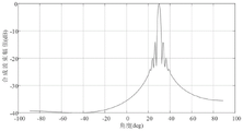
图6是时域下各离散时间点合成之后的波束合成图;FIG. 6 is a beamforming diagram after combining discrete time points in the time domain;
图7是相同参数下LFM和NLFM回波信号脉压对比图。Figure 7 is a comparison chart of pulse pressure of LFM and NLFM echo signals under the same parameters.
具体实施方式Detailed ways
下面结合附图对本发明的技术方案做进一步的详细说明。The technical solution of the present invention will be further described in detail below in conjunction with the accompanying drawings.
本发明提出的一种基于提取参数分数时延的宽带NLFM发射波束形成方法,如图1所示,具体实现步骤如下:A kind of broadband NLFM transmission beamforming method based on extraction parameter fractional time delay that the present invention proposes, as shown in Figure 1, specific implementation steps are as follows:
步骤1、为了使输出波形的距离旁瓣压低,选用汉明窗作为信号功率谱产生非线性调频信号波形,根据相位驻定原理得到信号的群延时函数和频谱,信号的相位函数

其中f为信号频率,B为调频带宽;信号的群延时函数T(f)和频谱f(t)为:Where f is the signal frequency, B is the FM bandwidth; the group delay function T(f) and frequency spectrum f(t) of the signal are:

f(t)=T-1(f)f(t)=T -1 (f)
其中K1为常系数;信号的相位函数


0≤t≤T0≤t≤T
其中T为调制波形的脉冲宽度,a(t)为包络。Among them, T is the pulse width of the modulation waveform, and a(t) is the envelope.
步骤2、在基于TTD的通用均匀线阵发射波束形成结构,M个相同的全向天线阵元辐射延迟波中进行发射波束时延划分,划分为整数时延和分数时延;
进行均匀线阵模型下的发射波束时延划分,具体过程为:Carry out the transmit beam delay division under the uniform linear array model, the specific process is as follows:
m阵元相比参考阵元(第一个阵元即0阵元)的传播路径差导致了时间差τtm:The propagation path difference between the m array element and the reference array element (the first array element is 0 array element) results in a time difference τ tm :

其中θt为波达角,c为光速,d为阵元间距,M为阵元个数;Where θ t is the angle of arrival, c is the speed of light, d is the distance between array elements, and M is the number of array elements;
在远场中,M个阵元时延后的发射信号sm(t-τtm)的瞬时线性组合为合成信号x(t):In the far field, the instantaneous linear combination of the transmitted signals s m (t-τ tm ) delayed by M array elements is the composite signal x(t):

其中sm(t)为第m+1个阵元延时前的发射信号,0<m<M-1;δ(t-τtm)为sm(t-τtm)函数的冲激函数;δ(t-τm-τtm)为δ(t-τm)和δ(t-τtm)的卷积函数,τm为信号在发射时第m+1个阵元相对于参考阵元的真实时延;若信号发射最大功率指向目标角度θt,则τm=-τtm;Where s m (t) is the transmitted signal before the delay of the m+1th array element, 0<m<M-1; δ(t-τ tm ) is the impulse function of the s m (t-τ tm ) function ; δ(t-τ m -τ tm ) is the convolution function of δ(t-τ m ) and δ(t-τ tm ), and τ m is the ratio of the m+1th array element to the reference array when the signal is transmitting The real time delay of the element; if the maximum power of signal transmission points to the target angle θ t , then τ m =-τ tm ;
根据采样周期Ts,真实时延τm划分为整数时延Tm和分数时延Fm为:According to the sampling period T s , the real time delay τ m is divided into integer time delay T m and fractional time delay F m as follows:

其中Intm是整数时延的个数,Round(·)表示四舍五入到最近的整数。Wherein Int m is the number of integer delays, and Round(·) means rounding to the nearest integer.
步骤3、对参考阵元波形s0(t)延后相应整数倍的采样周期,再根据m阵元的分数时延Fm产生分数时延波形,实现不同阵元的信号时延;
步骤3-1、通过信号的相位多项式函数得出参考阵元信号的相位;Step 3-1, obtain the phase of the reference array element signal through the phase polynomial function of the signal;
步骤3-2、根据参考阵元波形得出第m+1个阵元的延迟波形,0<m<M-1;Step 3-2. Obtain the delay waveform of the m+1th array element according to the waveform of the reference array element, 0<m<M-1;
步骤3-3、计算出包络时延和相移;Step 3-3, calculating the envelope delay and phase shift;
步骤3-4、根据包络时延和相移得到第m+1个阵元的分数时延波形。Step 3-4: Obtain the fractional delay waveform of the m+1th array element according to the envelope delay and phase shift.
提取参数的数字分数时延波形的产生,具体过程为:The generation of the digital fractional delay waveform of the extracted parameters, the specific process is:
参考阵元的波形s0(t)为:The waveform s 0 (t) of the reference array element is:

其中a0(t)为参考阵元信号的包络,


其中Pi,0根据f(t)离散值数值积分并拟合曲线得到,i=0,1,2,...,n-1,n,下标i代表参数对应指数i;则第m+1个阵元的延迟波形sm(t)为:Among them, P i, 0 is obtained according to f(t) discrete value numerical integration and curve fitting, i=0, 1, 2, ..., n-1, n, subscript i represents the parameter corresponding to index i; then the mth The delay waveform s m (t) of +1 array element is:

其中a0(t-Fm)为包络时延,
若要实现不同阵元的信号时延,可先对参考阵元波形s0(t)延后相应整数倍的采样周期,再根据分数时延Fm产生分数时延波形。实现分数时延需计算包络时延a0(t-Fm)和相移

若要不同阵元信号在θt方向同相位合成,则第m+1个阵元发射分数时延波形的相位参数应取Pi,m(i=0,1,2,...,n-1,n,下标i代表参数对应指数i,m代表阵元编号)。根据多项式的性质,知Pi,m的数值为:If different array element signals are synthesized in the same phase in the θ t direction, the phase parameter of the fractional delay waveform transmitted by the m+1th array element should be P i, m (i=0, 1, 2, ..., n -1, n, the subscript i represents the index corresponding to the parameter i, and m represents the array element number). According to the properties of polynomials, the value of P i, m is known as:

其中
第m+1阵元的分数时延波形为:The fractional delay waveform of the m+1th array element is:

其中A为恒包络。where A is the constant envelope.
步骤4、计算出基于相位累加器与CORDIC RM模块的通用数字信号处理结构的输入参数;根据输入参数生成宽带NLFM信号分数时延波形,再进行整数时延,形成完整的宽带NLFM发射波束。计算输入参数具体过程为:Step 4. Calculate the input parameters of the general digital signal processing structure based on the phase accumulator and the CORDIC RM module; generate the fractional delay waveform of the broadband NLFM signal according to the input parameters, and then carry out integer delay to form a complete broadband NLFM transmission beam. The specific process of calculating the input parameters is as follows:
采用G相数字信号处理结构,此时数字采样时钟为:The G-phase digital signal processing structure is adopted, and the digital sampling clock at this time is:

其中TCLK为时钟脉冲,G为数字信号处理结构的相数;时钟Ts下的采样序列编号为nt:Where T CLK is the clock pulse, G is the phase number of the digital signal processing structure; the sampling sequence number under the clock T s is n t :
nt=G·it+gn t =G i t +g
it=0,1,2,...,NG-1,NG=it/G,g=0,1,2,...,G-1i t = 0, 1, 2, ..., N G -1, N G = it /G, g = 0, 1, 2, ..., G- 1
其中it为多相结构中单相的采样序列,NG为单相采样序列的长度,g为每一相编号;Where it is the single-phase sampling sequence in the polyphase structure, N G is the length of the single-phase sampling sequence, and g is the number of each phase;
则对于参考阵元,第g+1相累加器结构输出相位表达式为:Then for the reference array element, the output phase expression of the g+1th phase accumulator structure is:


其中Ri,0,g为该式每项系数,i=1,2,3,...,n-1,n,下标i代表经过的累加器个数,0代表当前对应0阵元,为参考阵元,g代表多相结构中的第g+1项;Among them, R i, 0, g are the coefficients of each item of the formula, i=1, 2, 3, ..., n-1, n, the subscript i represents the number of accumulators passed, and 0 represents the current corresponding 0 array element , is the reference array element, and g represents the g+1th item in the multiphase structure;
第m+1个阵元离散相位函数表达式为:The expression of the discrete phase function of the m+1th array element is:

式中系数为Ri,m,g,i=1,2,3,...,n-1,n,下标i代表经过的累加器个数,m代表当前阵元的编号;多相数字信号处理结构中,第g+1相输入参数为:In the formula, the coefficients are R i, m, g , i=1, 2, 3, ..., n-1, n, the subscript i represents the number of accumulators passed, and m represents the number of the current array element; multi-phase In the digital signal processing structure, the input parameters of the g+1th phase are:

其中RWm,g、FWi,m,g、PWm,g都为数字信号处理结构的输入参数,参见图2。Among them, RW m, g , FW i, m, g , and PW m, g are input parameters of the digital signal processing structure, as shown in Fig. 2 .
本发明的算法和处理方法已通过验证,取得了满意的应用效果:Algorithm and processing method of the present invention have passed verification, obtained satisfactory application effect:
1.实验条件1. Experimental conditions
以带宽B=400MHz,脉冲宽度T=10us,中心频率fc=200MHz的NLFM信号作为输入信号,采样频率fs=1600MHz,期望发射方向θt为30°,阵元个数M为64,阵元间距d为λc/2,λc=c/fc。Taking the NLFM signal with bandwidth B=400MHz, pulse width T=10us, center frequency f c =200MHz as the input signal, sampling frequency f s =1600MHz, expected emission direction θ t is 30°, the number of array elements M is 64, the array The element distance d is λ c /2, λ c =c/f c .
2.仿真内容2. Simulation content
仿真1:采用5阶,16阶,50阶拟合后得到的信号脉冲压缩图线。可以发现,在取16阶拟合时,脉冲压缩后副瓣已达到-40dB以下,且随着阶数提高,拟合精度改善已不明显。图3为不同拟合阶数下的脉压结果。Simulation 1: Using the 5th order, 16th order, and 50th order fitting, the signal pulse compression curve is obtained. It can be found that when the 16th order is used for fitting, the sidelobe has reached below -40dB after pulse compression, and as the order increases, the improvement of fitting accuracy is not obvious. Figure 3 shows the pulse pressure results under different fitting orders.
仿真2:使用4相数字信号处理系统(G=4),将计算参数输入系统,得到各阵元的数字宽带分数时延发射波形,以0,1阵元为例,图4,图5分别为参考阵元和第二阵元四相输出波形,a为FPGA仿真测试结果,b为MATLAB仿真结果。Simulation 2: Using a 4-phase digital signal processing system (G=4), input the calculation parameters into the system to obtain the digital wideband fractional time-delay transmission waveforms of each array element. Taking the 0 and 1 array elements as an example, Fig. 4 and Fig. 5 respectively The four-phase output waveforms of the reference array element and the second array element, a is the FPGA simulation test result, and b is the MATLAB simulation result.
仿真3:在使用本发明提出的整数时延后提取参数形成分数时延波形方法,图6为时域下各离散时间点合成之后的波束合成图。Simulation 3: Using the integer time delay proposed by the present invention to extract parameters to form a fractional time delay waveform method, Fig. 6 is a beamforming diagram after combining discrete time points in the time domain.
仿真4:相同参数条件下,宽带NLFM信号和LFM信号回波脉冲压缩后的对比。为方便比较,观察时间未覆盖整个时宽。图7为相同参数下LFM和NLFM回波信号脉压对比。Simulation 4: Under the same parameter conditions, the comparison of wideband NLFM signal and LFM signal after echo pulse compression. For comparison, the observation time does not cover the entire duration. Figure 7 shows the pulse pressure comparison of LFM and NLFM echo signals under the same parameters.
3.仿真结果分析3. Simulation result analysis
从图3可知,在取16阶拟合时,脉冲压缩后副瓣已达到-40dB以下,且随着阶数提高,拟合精度改善已不明显。从图4图5可知,FPGA仿真结果与MATLAB软件仿真结果一致,该方法产生了准确的分数时延波形。从图6可知,波束准确指向预先设定的30°,发射波束的合成方向良好,没有明显偏移失真。从图7可知,相比LFM信号,NLFM信号会略微展宽主瓣,但是副瓣明显降低,降低幅度超过20dB,改善明显。It can be seen from Figure 3 that when the 16-order fitting is used, the sidelobe has reached below -40dB after pulse compression, and the improvement of the fitting accuracy is not obvious as the order increases. It can be seen from Figure 4 and Figure 5 that the FPGA simulation results are consistent with the MATLAB software simulation results, and this method produces accurate fractional delay waveforms. It can be seen from Figure 6 that the beam is accurately pointed to the preset 30°, the combined direction of the transmitted beam is good, and there is no obvious offset distortion. It can be seen from Figure 7 that compared with the LFM signal, the NLFM signal will slightly broaden the main lobe, but the side lobe is significantly reduced, and the reduction is more than 20dB, which is an obvious improvement.
Claims (5)


Priority Applications (1)
| Application Number | Priority Date | Filing Date | Title |
|---|---|---|---|
| CN202011355255.1A CN112526458B (en) | 2020-11-27 | 2020-11-27 | Broadband NLFM (non-line-of-sight) emission beam forming method based on parameter fraction time delay extraction |
Applications Claiming Priority (1)
| Application Number | Priority Date | Filing Date | Title |
|---|---|---|---|
| CN202011355255.1A CN112526458B (en) | 2020-11-27 | 2020-11-27 | Broadband NLFM (non-line-of-sight) emission beam forming method based on parameter fraction time delay extraction |
Publications (2)
| Publication Number | Publication Date |
|---|---|
| CN112526458A CN112526458A (en) | 2021-03-19 |
| CN112526458B true CN112526458B (en) | 2022-11-11 |
Family
ID=74994102
Family Applications (1)
| Application Number | Title | Priority Date | Filing Date |
|---|---|---|---|
| CN202011355255.1A Active CN112526458B (en) | 2020-11-27 | 2020-11-27 | Broadband NLFM (non-line-of-sight) emission beam forming method based on parameter fraction time delay extraction |
Country Status (1)
| Country | Link |
|---|---|
| CN (1) | CN112526458B (en) |
Families Citing this family (4)
| Publication number | Priority date | Publication date | Assignee | Title |
|---|---|---|---|---|
| CN113625230B (en) * | 2021-07-22 | 2023-07-04 | 中国科学院空天信息创新研究院 | Fourier series-based low sidelobe nonlinear frequency modulation waveform optimization method |
| CN114245265B (en) * | 2021-11-26 | 2022-12-06 | 南京航空航天大学 | A Design Method of Polynomial Structured Beamformer with Beam Pointing Self-correction Capability |
| CN117949903B (en) * | 2024-03-26 | 2024-05-28 | 中国科学院空天信息创新研究院 | A method and device for generating nonlinear frequency modulation signals of arbitrary time width and bandwidth in real time |
| CN118554987B (en) * | 2024-07-26 | 2024-10-25 | 西安欣创电子技术有限公司 | FPGA-based low-overhead ultra-wideband digital beam forming method and system |
Family Cites Families (8)
| Publication number | Priority date | Publication date | Assignee | Title |
|---|---|---|---|---|
| CN101383651B (en) * | 2008-10-24 | 2012-02-15 | 西北工业大学 | Near field time domain beam forming method suitable for wideband signal |
| KR101019075B1 (en) * | 2009-05-18 | 2011-03-07 | (주)밀리시스 | Radar signal processing apparatus and method using nonlinear frequency modulated waveform |
| US8305262B1 (en) * | 2010-03-08 | 2012-11-06 | Lockheed Martin Corporation | Mismatched pulse compression of nonlinear FM signal |
| CN103197318B (en) * | 2013-03-18 | 2014-10-08 | 中国科学院声学研究所 | Time delay estimation method based on the Pattern delay coding underwater acoustic positioning |
| CN106301498B (en) * | 2016-08-17 | 2020-01-14 | 河海大学 | Sub-band processing method and frequency-space cascade broadband adaptive beam acquisition method |
| CN109765528B (en) * | 2019-01-17 | 2020-12-15 | 中国科学院电子学研究所 | A kind of real-time generation method and device of nonlinear frequency modulation signal |
| CN110412522B (en) * | 2019-07-02 | 2023-05-26 | 艾索信息股份有限公司 | NLFM waveform design method |
| CN110308445B (en) * | 2019-07-18 | 2022-10-04 | 中国电子科技集团公司第二十九研究所 | Imaging method based on vehicle-mounted digital array frequency modulation continuous wave radar |
-
2020
- 2020-11-27 CN CN202011355255.1A patent/CN112526458B/en active Active
Also Published As
| Publication number | Publication date |
|---|---|
| CN112526458A (en) | 2021-03-19 |
Similar Documents
| Publication | Publication Date | Title |
|---|---|---|
| CN112526458B (en) | Broadband NLFM (non-line-of-sight) emission beam forming method based on parameter fraction time delay extraction | |
| Rice et al. | Quadrature sampling with high dynamic range | |
| CN110927680B (en) | Broadband receiving digital beam forming method based on digital deskew and frequency domain equalization | |
| CN110308427B (en) | Pulse Compression Processing Method in Frequency Domain of LFM Pulse Radar Based on FPGA | |
| CN101833082B (en) | Wideband frequency-modulation stepping signal processing method based on full deskew | |
| CN108650048B (en) | A high-precision digital array multi-channel delay compensation method | |
| CN101296014A (en) | A Broadband Digital Beamforming Method | |
| US20160018512A1 (en) | Method for Generating and Compressing Multi-Sweep-Frequency Radar Signals | |
| CN109525256A (en) | A kind of channelizing emitting structural of the narrow transition band filter group based on FPGA | |
| JP4444057B2 (en) | Pulse compression processor | |
| CN104076342A (en) | Method for predicting target RCS in radar tracking state | |
| CN103776907B (en) | Ultrasonic phase array based on sinc interpolation receives signal essence time-delay method | |
| JP4834370B2 (en) | Correlation reception processing device | |
| Jiang et al. | Design and realization of FPGA-based DRFM with high instantaneous bandwidth | |
| CN109633613A (en) | A kind of FPGA implementation method of hypersonic Platform Alliance pulse compression and the compensation of bullet speed | |
| CN220543105U (en) | Arbitrary target simulation system based on multiple scattering centers | |
| Shehata et al. | Design and implementation of lfmcw radar signal processor for slowly moving target detection using fpga | |
| CN111917676A (en) | A chirp interference cancellation method | |
| Deng | Wideband digital fractional time delay waveform generation method based on polynomial fitting | |
| Chen et al. | Implementation of Wideband DBF for Large Aperture Phased Array Radar Based on FPGA | |
| Vizitiu | Sidelobes reduction using synthesis of some NLFM laws | |
| Yan et al. | Design and FPGA implementation of digital pulse compression for chirp radar based on CORDIC | |
| Liou et al. | Digital wideband phased array calibration and beamforming using time reversal technique | |
| Gao et al. | Improved spectrum reconstruction technique based on chirp rate modulation in stepped-frequency SAR | |
| Liu et al. | Eliminating ghost images in high-range resolution profiles for stepped-frequency train of linear frequency modulation pulses |
Legal Events
| Date | Code | Title | Description |
|---|---|---|---|
| PB01 | Publication | ||
| PB01 | Publication | ||
| SE01 | Entry into force of request for substantive examination | ||
| SE01 | Entry into force of request for substantive examination | ||
| GR01 | Patent grant | ||
| GR01 | Patent grant |