CN111918606A - Catheter with staggered electrode spine assembly - Google Patents
Catheter with staggered electrode spine assembly Download PDFInfo
- Publication number
- CN111918606A CN111918606A CN201980012089.4A CN201980012089A CN111918606A CN 111918606 A CN111918606 A CN 111918606A CN 201980012089 A CN201980012089 A CN 201980012089A CN 111918606 A CN111918606 A CN 111918606A
- Authority
- CN
- China
- Prior art keywords
- microelectrodes
- ridge
- catheter
- ridges
- distal
- Prior art date
- Legal status (The legal status is an assumption and is not a legal conclusion. Google has not performed a legal analysis and makes no representation as to the accuracy of the status listed.)
- Granted
Links
Images


Classifications
-
- A—HUMAN NECESSITIES
- A61—MEDICAL OR VETERINARY SCIENCE; HYGIENE
- A61B—DIAGNOSIS; SURGERY; IDENTIFICATION
- A61B5/00—Measuring for diagnostic purposes; Identification of persons
- A61B5/68—Arrangements of detecting, measuring or recording means, e.g. sensors, in relation to patient
- A61B5/6846—Arrangements of detecting, measuring or recording means, e.g. sensors, in relation to patient specially adapted to be brought in contact with an internal body part, i.e. invasive
- A61B5/6847—Arrangements of detecting, measuring or recording means, e.g. sensors, in relation to patient specially adapted to be brought in contact with an internal body part, i.e. invasive mounted on an invasive device
- A61B5/6852—Catheters
- A61B5/6859—Catheters with multiple distal splines
-
- A—HUMAN NECESSITIES
- A61—MEDICAL OR VETERINARY SCIENCE; HYGIENE
- A61B—DIAGNOSIS; SURGERY; IDENTIFICATION
- A61B5/00—Measuring for diagnostic purposes; Identification of persons
- A61B5/24—Detecting, measuring or recording bioelectric or biomagnetic signals of the body or parts thereof
- A61B5/25—Bioelectric electrodes therefor
- A61B5/279—Bioelectric electrodes therefor specially adapted for particular uses
- A61B5/28—Bioelectric electrodes therefor specially adapted for particular uses for electrocardiography [ECG]
- A61B5/283—Invasive
- A61B5/287—Holders for multiple electrodes, e.g. electrode catheters for electrophysiological study [EPS]
-
- A—HUMAN NECESSITIES
- A61—MEDICAL OR VETERINARY SCIENCE; HYGIENE
- A61B—DIAGNOSIS; SURGERY; IDENTIFICATION
- A61B5/00—Measuring for diagnostic purposes; Identification of persons
- A61B5/24—Detecting, measuring or recording bioelectric or biomagnetic signals of the body or parts thereof
- A61B5/25—Bioelectric electrodes therefor
- A61B5/279—Bioelectric electrodes therefor specially adapted for particular uses
- A61B5/28—Bioelectric electrodes therefor specially adapted for particular uses for electrocardiography [ECG]
- A61B5/283—Invasive
-
- A—HUMAN NECESSITIES
- A61—MEDICAL OR VETERINARY SCIENCE; HYGIENE
- A61B—DIAGNOSIS; SURGERY; IDENTIFICATION
- A61B5/00—Measuring for diagnostic purposes; Identification of persons
- A61B5/68—Arrangements of detecting, measuring or recording means, e.g. sensors, in relation to patient
- A61B5/6846—Arrangements of detecting, measuring or recording means, e.g. sensors, in relation to patient specially adapted to be brought in contact with an internal body part, i.e. invasive
- A61B5/6847—Arrangements of detecting, measuring or recording means, e.g. sensors, in relation to patient specially adapted to be brought in contact with an internal body part, i.e. invasive mounted on an invasive device
- A61B5/6852—Catheters
-
- A—HUMAN NECESSITIES
- A61—MEDICAL OR VETERINARY SCIENCE; HYGIENE
- A61M—DEVICES FOR INTRODUCING MEDIA INTO, OR ONTO, THE BODY; DEVICES FOR TRANSDUCING BODY MEDIA OR FOR TAKING MEDIA FROM THE BODY; DEVICES FOR PRODUCING OR ENDING SLEEP OR STUPOR
- A61M25/00—Catheters; Hollow probes
- A61M25/01—Introducing, guiding, advancing, emplacing or holding catheters
- A61M25/0105—Steering means as part of the catheter or advancing means; Markers for positioning
- A61M25/0133—Tip steering devices
- A61M25/0147—Tip steering devices with movable mechanical means, e.g. pull wires
-
- A—HUMAN NECESSITIES
- A61—MEDICAL OR VETERINARY SCIENCE; HYGIENE
- A61B—DIAGNOSIS; SURGERY; IDENTIFICATION
- A61B18/00—Surgical instruments, devices or methods for transferring non-mechanical forms of energy to or from the body
- A61B2018/00053—Mechanical features of the instrument of device
- A61B2018/00214—Expandable means emitting energy, e.g. by elements carried thereon
- A61B2018/00267—Expandable means emitting energy, e.g. by elements carried thereon having a basket shaped structure
-
- A—HUMAN NECESSITIES
- A61—MEDICAL OR VETERINARY SCIENCE; HYGIENE
- A61B—DIAGNOSIS; SURGERY; IDENTIFICATION
- A61B18/00—Surgical instruments, devices or methods for transferring non-mechanical forms of energy to or from the body
- A61B18/04—Surgical instruments, devices or methods for transferring non-mechanical forms of energy to or from the body by heating
- A61B18/12—Surgical instruments, devices or methods for transferring non-mechanical forms of energy to or from the body by heating by passing a current through the tissue to be heated, e.g. high-frequency current
- A61B18/14—Probes or electrodes therefor
- A61B2018/1467—Probes or electrodes therefor using more than two electrodes on a single probe
-
- A—HUMAN NECESSITIES
- A61—MEDICAL OR VETERINARY SCIENCE; HYGIENE
- A61B—DIAGNOSIS; SURGERY; IDENTIFICATION
- A61B5/00—Measuring for diagnostic purposes; Identification of persons
- A61B5/06—Devices, other than using radiation, for detecting or locating foreign bodies ; Determining position of diagnostic devices within or on the body of the patient
- A61B5/061—Determining position of a probe within the body employing means separate from the probe, e.g. sensing internal probe position employing impedance electrodes on the surface of the body
- A61B5/062—Determining position of a probe within the body employing means separate from the probe, e.g. sensing internal probe position employing impedance electrodes on the surface of the body using magnetic field
Landscapes
- Health & Medical Sciences (AREA)
- Life Sciences & Earth Sciences (AREA)
- Engineering & Computer Science (AREA)
- General Health & Medical Sciences (AREA)
- Animal Behavior & Ethology (AREA)
- Biophysics (AREA)
- Biomedical Technology (AREA)
- Heart & Thoracic Surgery (AREA)
- Veterinary Medicine (AREA)
- Public Health (AREA)
- Molecular Biology (AREA)
- Surgery (AREA)
- Physics & Mathematics (AREA)
- Pathology (AREA)
- Medical Informatics (AREA)
- Cardiology (AREA)
- Physiology (AREA)
- Pulmonology (AREA)
- Anesthesiology (AREA)
- Hematology (AREA)
- Mechanical Engineering (AREA)
- Human Computer Interaction (AREA)
- Measurement And Recording Of Electrical Phenomena And Electrical Characteristics Of The Living Body (AREA)
- Surgical Instruments (AREA)
- Electrotherapy Devices (AREA)
Abstract
Description
技术领域technical field
本发明涉及一种电生理导管,具体地讲,涉及一种具有电极构型的心脏电生理导管,所述电极构型提供对分级信号的更准确且更独立的感测。The present invention relates to an electrophysiological catheter, and in particular, to a cardiac electrophysiological catheter having an electrode configuration that provides more accurate and independent sensing of graded signals.
背景技术Background technique
电极导管已经普遍用于医疗实践多年。它们被用来刺激和标测心脏中的电活动,以及用来消融异常电活动的位点。Leads have been commonly used in medical practice for many years. They are used to stimulate and map electrical activity in the heart, and to ablate sites of abnormal electrical activity.
使用时,电极导管被插入主要的静脉或动脉(例如股动脉),然后导入所关注的心脏的腔室中。一旦导管被定位在心脏内,心脏内的异常电活动的位置就被定位。In use, the lead is inserted into a major vein or artery (eg, the femoral artery) and then introduced into the chamber of the heart of interest. Once the catheter is positioned within the heart, the location of abnormal electrical activity within the heart is located.
一种定位技术涉及电生理标测规程,由此从导电心内组织发出的电信号得到系统监测,并且由这些信号形成标测图。通过分析该标测图,医师可识别干涉电通路。用于对来自导电心脏组织的电信号进行标测的常规方法是经由皮肤引入电生理导管(电极导管),该电生理导管具有安装在其远侧末端上的标测电极。导管被操纵以将这些电极放置成与心内膜接触。通过监测心内膜处的电信号,可查明导致心律不齐的异常导电组织位点。One localization technique involves electrophysiological mapping procedures whereby electrical signals emanating from conductive intracardiac tissue are systematically monitored and maps are formed from these signals. By analyzing this map, the physician can identify interfering electrical pathways. A conventional method for mapping electrical signals from conductive cardiac tissue is to introduce an electrophysiological catheter (electrode catheter) percutaneously with a mapping electrode mounted on its distal tip. The catheter is manipulated to place these electrodes in contact with the endocardium. By monitoring electrical signals at the endocardium, the site of abnormally conductive tissue that causes arrhythmias can be pinpointed.
对于通过安装在导管上的环形电极进行的感测,从环形电极传输信号的引线电连接到导管控制手柄的远侧端部中的合适连接器,该连接器电连接到ECG监测系统和/或合适的3D电生理(EP)标测系统,例如购自Biosense Webster,Inc.(Irwindale,California)的CARTO、CARTO XP或CARTO 3。For sensing by a ring electrode mounted on the catheter, the lead wire transmitting the signal from the ring electrode is electrically connected to a suitable connector in the distal end of the catheter control handle that is electrically connected to the ECG monitoring system and/or Suitable 3D electrophysiological (EP) mapping systems such as CARTO, CARTO XP or CARTO 3 from Biosense Webster, Inc. (Irwindale, California).
相对于远场信号,更小且更紧密间隔的电极对允许更准确地检测近场电势,在试图处理心脏的特定区域时,这种检测可能非常重要。例如,近场肺静脉电势为非常小的信号,而位置非常靠近肺静脉的心房提供大得多的信号。因此,即使当导管被放置于肺静脉区域中时,电生理学家仍可能难以确定信号是小的近电势(来自肺静脉)还是较大的较远电势(来自心房)。更小且紧密间隔的双极允许医师更准确地移除远场信号并获得局部组织中电活动的更准确读数。因此,通过具有更小且紧密间隔的电极,能够精确地瞄准具有肺静脉电势的心肌组织的位置,并且因此允许临床医生将治疗递送至特定组织。此外,更小且紧密间隔的电极允许医师通过电信号确定心门的精确解剖位置。Smaller and more closely spaced electrode pairs allow for more accurate detection of near-field potentials relative to far-field signals, which can be important when trying to address specific regions of the heart. For example, the near-field pulmonary vein potential is a very small signal, whereas the atria, located very close to the pulmonary veins, provide a much larger signal. Therefore, even when the catheter is placed in the pulmonary vein region, it may be difficult for an electrophysiologist to determine whether the signal is a small near potential (from the pulmonary vein) or a larger, more distant potential (from the atrium). Smaller and closely spaced bipolars allow physicians to more accurately remove far-field signals and obtain more accurate readings of electrical activity in local tissue. Thus, by having smaller and closely spaced electrodes, the location of myocardial tissue with pulmonary venous potential can be precisely targeted, and thus allow clinicians to deliver therapy to specific tissues. In addition, smaller and closely spaced electrodes allow physicians to determine the precise anatomical location of the hilum via electrical signals.
增加电极密度(例如,通过增加导管上承载的多个电极)也提高了检测精度。然而,导管上承载的电极越多,尤其是电极密度越高,电极碰触和短路的风险就会增加。此外,总是期望改善与高柔性电极组件结构的电极组织接触,所述结构可以可靠地进行接触,但接触的方式使电极承载结构以可控和可预测的方式工作而不刺穿或损伤组织。随着用于构造这些结构的材料变得更加柔性和精细,在导管组装期间较小的环形电极及其支撑结构变形、尤其是伸长的风险增加。此外,随着电极组件结构变得更加精细,部件分离、扭结和缠结的风险增加。Increasing electrode density (eg, by increasing the number of electrodes carried on the catheter) also improves detection accuracy. However, the more electrodes that are carried on the catheter, especially the higher the electrode density, the greater the risk of electrode touching and shorting. Furthermore, it is always desirable to improve electrode tissue contact with highly flexible electrode assembly structures that can make contact reliably but in a manner that allows the electrode carrying structure to function in a controlled and predictable manner without piercing or damaging tissue . As the materials used to construct these structures become more flexible and delicate, the risk of deformation, especially elongation, of the smaller ring electrodes and their supporting structures increases during catheter assembly. Furthermore, as electrode assembly structures become finer, the risk of component separation, kinking, and entanglement increases.
还已经观察到,当电极彼此碰触或发生接触时,通过电极的信号采集受到不利影响。在标测期间,当操作者操纵导管的远侧电极组件时,尤其是当操作者沿组织表面“扫过”该组件时,可能发生接触和碰撞。电极之间的接触和碰撞可能产生伪影,这些伪影不利地影响ECG信号的质量和标测图生成。It has also been observed that signal acquisition through the electrodes is adversely affected when the electrodes touch or come into contact with each other. During mapping, contacts and collisions may occur as the operator manipulates the distal electrode assembly of the catheter, especially as the operator "sweeps" the assembly along the tissue surface. Contact and collision between electrodes can produce artifacts that adversely affect ECG signal quality and map generation.
因此,需要具有紧密间隔的微电极以实现高电极密度的电生理导管。还需要具有电极承载结构的电生理导管,这些电极承载结构在构造上是精细的,以提供期望的柔性,但是在组织接触时其移动是可预测的。还需要使电极碰触和短路的风险最小化的电生理导管。Therefore, electrophysiological catheters with closely spaced microelectrodes to achieve high electrode density are required. There is also a need for electrophysiological catheters with electrode bearing structures that are finely constructed to provide the desired flexibility, but whose movement is predictable upon tissue contact. There is also a need for electrophysiological catheters that minimize the risk of electrode touching and shorting.
发明内容SUMMARY OF THE INVENTION
本发明涉及具有远侧电极组件的电生理导管,该远侧电极组件在可于组织表面区域上柔性地伸展的多个分散的脊上承载非常小且紧密间隔的微电极,以便同时在多个位置处检测信号,并同时最大程度减少对不期望的噪声(包括远场信号)的检测。远侧电极组件被配置为适形于心脏的心房腔中的组织的不同解剖结构。脊具有曲线区段或带直线区段的曲线区段,以便对不同组织表面具有宽范围的适应性,同时在不同的区段提供机械优点,以改善柔韧性和刚性,从而便于更好地接触组织。每个脊从其近侧端部到其远侧端部具有大致锥形构型,以用于提供更坚固、更刚性的近侧基部和更柔性的远侧端部,以便改善柔韧性特征,同时使脊碰触或缠结的风险最小化。The present invention relates to an electrophysiological catheter having a distal electrode assembly carrying very small and closely spaced microelectrodes on a plurality of discrete ridges that can be flexibly stretched over a tissue surface area for simultaneous Signals are detected at the location while minimizing the detection of undesired noise, including far-field signals. The distal electrode assembly is configured to conform to different anatomies of tissue in the atrial cavity of the heart. Ridges have curvilinear sections or curvilinear sections with straight sections for a wide range of adaptability to different tissue surfaces, while providing mechanical advantages in different sections to improve flexibility and rigidity for better contact organize. Each ridge has a generally tapered configuration from its proximal end to its distal end for providing a stronger, more rigid proximal base and a more flexible distal end for improved flexibility characteristics, At the same time the risk of ridges touching or tangling is minimized.
在一些实施方案中,电生理导管具有细长主体和远侧电极组件。远侧电极组件具有近侧杆、从近侧杆发出的多个脊以及多个非导电脊覆盖件,每个脊覆盖件围绕相应的脊,每个脊覆盖件具有嵌入在覆盖件的侧壁中的多个拉伸构件。In some embodiments, the electrophysiological catheter has an elongated body and a distal electrode assembly. The distal electrode assembly has a proximal stem, a plurality of ridges emanating from the proximal stem, and a plurality of non-conductive ridge covers, each ridge cover surrounding a corresponding ridge, each ridge cover having a sidewall embedded in the cover Multiple tensile members in .
在一些实施方案中,拉伸构件在纵向方向上延伸。In some embodiments, the tensile members extend in the longitudinal direction.
在一些实施方案中,拉伸构件具有在纵向方向上延伸的部分。In some embodiments, the tensile member has portions that extend in the longitudinal direction.
在一些实施方案中,拉伸构件包括导线。In some embodiments, the tensile member includes a wire.
在一些实施方案中,拉伸构件包括纤维。In some embodiments, the tensile member includes fibers.
在一些实施方案中,电生理导管具有细长主体和远侧电极组件。远侧电极组件具有近侧杆和多个脊,每个脊具有扩大的远侧部分,该扩大的远侧部分具有通孔。远侧电极组件还具有多个非导电脊覆盖件,每个脊覆盖件围绕相应的脊。远侧电极组件还具有封装扩大的远侧部分的帽覆盖件,该帽覆盖件具有延伸穿过通孔的部分。In some embodiments, the electrophysiological catheter has an elongated body and a distal electrode assembly. The distal electrode assembly has a proximal stem and a plurality of ridges, each ridge having an enlarged distal portion having a through hole. The distal electrode assembly also has a plurality of non-conductive ridge covers, each ridge cover surrounding a corresponding ridge. The distal electrode assembly also has a cap cover enclosing the enlarged distal portion, the cap cover having a portion extending through the through hole.
在一些实施方案中,电生理导管具有细长主体和远侧电极组件。远侧电极组件具有近侧杆和数量为至少八个的多个脊,每个脊具有第一节段和线性节段,该第一节段具有由第一半径限定的第一预成形曲率。远侧电极组件还具有多个非导电脊覆盖件和多个微电极,其中每个脊上具有至少一个微电极。In some embodiments, the electrophysiological catheter has an elongated body and a distal electrode assembly. The distal electrode assembly has a proximal stem and a plurality of ridges in number of at least eight, each ridge having a first segment and a linear segment, the first segment having a first pre-shaped curvature defined by a first radius. The distal electrode assembly also has a plurality of non-conductive ridge covers and a plurality of microelectrodes, with at least one microelectrode on each ridge.
在一些实施方案中,每个脊包括具有第二预成形曲率的第二节段,该第二预成形曲率由不同于第一半径的第二半径限定,具有第二预成形曲率的第二节段位于具有第一预成形曲率的第一节段的远侧。In some embodiments, each ridge includes a second segment having a second preformed curvature defined by a second radius different from the first radius, the second segment having the second preformed curvature The segment is distal to the first segment having the first preformed curvature.
在一些实施方案中,第一半径小于第二半径。In some embodiments, the first radius is smaller than the second radius.
在一些实施方案中,第二预成形曲率与第一预成形曲率相反。In some embodiments, the second preform curvature is opposite to the first preform curvature.
在一些实施方案中,具有第二预成形曲率的第二节段位于具有第一预成形曲率的第一节段的远侧。In some embodiments, the second segment having the second preformed curvature is distal to the first segment having the first preformed curvature.
在一些实施方案中,在一些实施方案中,线性节段位于具有第一预成形曲率的第一节段与具有第二预成形曲率的第二节段之间。In some embodiments, the linear segment is located between a first segment having a first preformed curvature and a second segment having a second preformed curvature.
在一些实施方案中,具有线性节段的第二节段位于具有第二预成形曲率的第二节段的远侧。In some embodiments, the second segment having the linear segment is distal to the second segment having the second preformed curvature.
在一些实施方案中,每个被覆盖的脊具有小于3弗伦奇(french)的外周长。In some embodiments, each covered ridge has an outer perimeter of less than 3 French.
在一些实施方案中,该外周长为约2.6弗伦奇。In some embodiments, the outer perimeter is about 2.6 French.
在一些实施方案中,电生理导管具有细长主体和远侧电极组件。远侧电极组件具有近侧部分和多个脊,每个脊具有线性锥度,该线性锥度具有较宽的近侧端部和较窄的远侧端部。远侧电极组件还具有多个非导电脊覆盖件,每个非导电脊覆盖件围绕相应的脊。In some embodiments, the electrophysiological catheter has an elongated body and a distal electrode assembly. The distal electrode assembly has a proximal portion and a plurality of ridges, each ridge having a linear taper with a wider proximal end and a narrower distal end. The distal electrode assembly also has a plurality of non-conductive ridge covers, each non-conductive ridge cover surrounding a corresponding ridge.
在一些实施方案中,该线性锥度是连续的。In some embodiments, the linear taper is continuous.
在一些实施方案中,该线性锥度是不连续的。In some embodiments, the linear taper is discontinuous.
在一些实施方案中,该不连续的线性锥度包括凹入部分,该凹入部分的宽度小于更近侧杆的宽度和更远侧部分的宽度。In some embodiments, the discontinuous linear taper includes a concave portion having a width that is less than the width of the more proximal rod and the width of the more distal portion.
在一些实施方案中,脊具有沿侧向边缘的铰链,该铰链被构造用于脊的平面内偏转。In some embodiments, the spine has hinges along the lateral edges configured for in-plane deflection of the spine.
在一些实施方案中,电生理导管具有细长主体和远侧电极组件。远侧电极组件具有近侧杆、数量为至少八个的多个脊,每个脊具有线性锥度,该线性锥度具有较宽的近侧端部和较窄的远侧端部。远侧电极组件还具有多个非导电脊覆盖件,每个非导电覆盖件围绕相应的脊。远侧电极组件还具有多个微电极,所述多个为至少约48个,每个微电极具有约480μm的长度。In some embodiments, the electrophysiological catheter has an elongated body and a distal electrode assembly. The distal electrode assembly has a proximal rod, a plurality of ridges in number of at least eight, each ridge having a linear taper having a wider proximal end and a narrower distal end. The distal electrode assembly also has a plurality of non-conductive ridge covers, each non-conductive cover surrounding a corresponding ridge. The distal electrode assembly also has a plurality of microelectrodes, the plurality being at least about 48, each microelectrode having a length of about 480 μm.
在一些实施方案中,每个脊上的微电极被分隔开如在微电极的前缘之间测量的介于约1mm与3mm之间的范围内的距离。In some embodiments, the microelectrodes on each ridge are separated by a distance ranging between about 1 mm and 3 mm as measured between the leading edges of the microelectrodes.
在一些实施方案中,该距离为约2mm。In some embodiments, the distance is about 2 mm.
在一些实施方案中,每个脊上的微电极被布置为双极对,其中一对内的微电极的前缘被分隔开介于约1mm与3mm之间的范围内的第一距离,并且其中多对之间的前微电极的前缘被分隔开介于1mm与6mm之间的范围内的第二距离。In some embodiments, the microelectrodes on each ridge are arranged as bipolar pairs, wherein the leading edges of the microelectrodes within a pair are separated by a first distance ranging between about 1 mm and 3 mm, and wherein the leading edges of the front microelectrodes between the pairs are separated by a second distance ranging between 1 mm and 6 mm.
在一些实施方案中,第一距离为约2mm,并且第二距离为约6mm。In some embodiments, the first distance is about 2 mm and the second distance is about 6 mm.
在一些实施方案中,多个微电极等于约64个。In some embodiments, the plurality of microelectrodes equals about 64.
在一些实施方案中,多个微电极等于约72个。In some embodiments, the plurality of microelectrodes equals about 72.
在一些实施方案中,第一环形电极被承载在远侧电极组件的近侧杆上,并且第二环形电极和第三环形电极被承载在细长主体的远侧部分上。In some embodiments, the first ring electrode is carried on the proximal stem of the distal electrode assembly, and the second and third ring electrodes are carried on the distal portion of the elongated body.
在一些实施方案中,电生理导管具有细长主体和远侧电极组件。远侧电极组件具有近侧杆,该近侧杆限定围绕纵向轴线的周长。远侧电极组件还具有从近侧杆发出并且在其远侧端部处发散的多个脊,所述多个脊围绕杆的周长在第一脊与第二脊之间交替。远侧电极组件还具有多个非导电脊覆盖件和多个微电极,每个脊覆盖件围绕相应的脊,多个微电极具有关于第一脊和第二脊的交错构型,其中每个第一脊上的最近侧微电极被定位在距近侧杆较大距离处,并且每个第二脊上的最近侧电极被定位在距近侧杆较小距离处。In some embodiments, the electrophysiological catheter has an elongated body and a distal electrode assembly. The distal electrode assembly has a proximal rod that defines a perimeter about the longitudinal axis. The distal electrode assembly also has a plurality of ridges emanating from the proximal shaft and diverging at its distal end, the plurality of ridges alternating between first and second ridges around the circumference of the shaft. The distal electrode assembly also has a plurality of non-conductive ridge covers and a plurality of microelectrodes, each ridge cover surrounding a corresponding ridge, the plurality of microelectrodes having a staggered configuration with respect to the first and second ridges, wherein each The proximal-most microelectrodes on the first ridge were positioned at a greater distance from the proximal rod, and the proximal-most electrodes on each second ridge were positioned at a smaller distance from the proximal rod.
所述交错电极构型为所述远侧电极组件提供了更大的有效接触表面,因为有效的同心电极阵列增加了或至少翻倍。The staggered electrode configuration provides a larger effective contact surface for the distal electrode assembly because the effective concentric electrode array is increased or at least doubled.
在一些实施方案中,远侧电极组件包括至少四个第一脊和四个第二脊,并且每个脊承载八个微电极。In some embodiments, the distal electrode assembly includes at least four first ridges and four second ridges, and each ridge carries eight microelectrodes.
在一些实施方案中,每个微电极具有约480μm的长度。In some embodiments, each microelectrode has a length of about 480 μm.
在一些实施方案中,每个脊上的微电极被分隔开如在微电极的前缘之间测量的介于约1mm与3mm之间的范围内的距离。In some embodiments, the microelectrodes on each ridge are separated by a distance ranging between about 1 mm and 3 mm as measured between the leading edges of the microelectrodes.
在一些实施方案中,该距离为约2mm。In some embodiments, the distance is about 2 mm.
在一些实施方案中,每个脊上的微电极被布置为双极对,其中一对内的微电极的前缘被分隔开介于约1mm与3mm之间的范围内的第一距离,并且其中多对之间的前微电极的前缘被分隔开介于1mm与6mm之间的范围内的第二距离。In some embodiments, the microelectrodes on each ridge are arranged as bipolar pairs, wherein the leading edges of the microelectrodes within a pair are separated by a first distance ranging between about 1 mm and 3 mm, and wherein the leading edges of the front microelectrodes between the pairs are separated by a second distance ranging between 1 mm and 6 mm.
在一些实施方案中,第一距离为约2mm,并且第二距离为约6mm。In some embodiments, the first distance is about 2 mm and the second distance is about 6 mm.
在一些实施方案中,电生理导管具有细长主体和远侧电极组件。远侧电极组件具有支撑结构,该支撑结构具有近侧杆,该近侧杆具有侧壁,该侧壁具有限定管腔的内表面,该侧壁具有开口。该支撑结构还具有从近侧杆发出并且在其远侧端部处发散的多个脊,以及多个非导电覆盖件,每个非导电覆盖件围绕相应的脊。远侧电极组件还具有在每个脊上的多个微电极,以及被接纳在杆的管腔中的外壳插入件,该外壳插入件具有外表面,在杆的外表面与内表面之间保留有空隙。粘合剂填充近侧杆的内表面与外壳插入件的外表面之间的空隙,粘合剂具有穿过近侧杆的侧壁中的开口的部分。In some embodiments, the electrophysiological catheter has an elongated body and a distal electrode assembly. The distal electrode assembly has a support structure having a proximal stem having a sidewall having an inner surface defining a lumen, the sidewall having an opening. The support structure also has a plurality of ridges emanating from the proximal rod and diverging at its distal end, and a plurality of non-conductive covers, each non-conductive cover surrounding a respective ridge. The distal electrode assembly also has a plurality of microelectrodes on each ridge, and a housing insert received in the lumen of the stem, the housing insert having an outer surface that remains between the outer and inner surfaces of the stem There are gaps. Adhesive fills the gap between the inner surface of the proximal rod and the outer surface of the housing insert, the adhesive having a portion passing through the opening in the sidewall of the proximal rod.
在一些实施方案中,外壳插入件具有管腔,该管腔的横截面具有细长的芸豆形构型。In some embodiments, the housing insert has a lumen having an elongated kidney bean-shaped configuration in cross-section.
在一些实施方案中,外壳插入件具有管腔,该管腔的横截面具有C形构型。In some embodiments, the housing insert has a lumen having a C-shaped configuration in cross-section.
在一些实施方案中,近侧杆中的开口提供了进入该杆的管腔的视觉通路,用于在组装期间检查延伸穿过其中的部件。此外,填充空隙的粘合剂通过开口注入或以其他方式施加。In some embodiments, an opening in the proximal rod provides visual access into the lumen of the rod for inspection of components extending therethrough during assembly. Additionally, the void-filling adhesive is injected or otherwise applied through the opening.
附图说明Description of drawings
当结合附图考虑时,通过参考以下具体实施方式,将更好地理解本发明的这些和其他特征以及优点。应当理解,所选择的结构和特征在某些附图中并没有示出,以便提供对其余的结构和特征的更好的观察。These and other features and advantages of the present invention will be better understood by reference to the following detailed description when considered in conjunction with the accompanying drawings. It should be understood that selected structures and features have not been shown in some of the drawings in order to provide a better view of the remaining structures and features.
图1为根据一个实施方案的本发明的导管的透视图。Figure 1 is a perspective view of a catheter of the present invention according to one embodiment.
图2为图1的导管的导管主体的端部剖视图。FIG. 2 is an end cross-sectional view of a catheter body of the catheter of FIG. 1 .
图3为图1的导管的偏转节段的端部剖视图。FIG. 3 is an end cross-sectional view of the deflection section of the catheter of FIG. 1 .
图4为根据一个实施方案的一体式支撑构件的透视图。4 is a perspective view of a unitary support member according to one embodiment.
图5A为根据一个实施方案的一体式支撑构件的侧视图。5A is a side view of a unitary support member according to one embodiment.
图5B为图5A的一体式支撑构件的详细视图。Figure 5B is a detailed view of the one-piece support member of Figure 5A.
图5C为沿线C-C截取的图5A的一体式支撑构件的端部剖视图。5C is an end cross-sectional view of the unitary support member of FIG. 5A taken along line C-C.
图5D为图5A的脊的扩大的远侧部分的详细视图。Figure 5D is a detailed view of an enlarged distal portion of the ridge of Figure 5A.
图5E为图5A的脊的端部剖视图的详细视图。5E is a detailed view of an end cross-sectional view of the ridge of FIG. 5A.
图6A为根据一个实施方案的一体式支撑构件的侧视图。6A is a side view of a unitary support member according to one embodiment.
图6B为图6A的一体式支撑构件的详细视图。Figure 6B is a detailed view of the one-piece support member of Figure 6A.
图6C为图6B的脊的远侧部分的详细视图。Figure 6C is a detailed view of the distal portion of the spine of Figure 6B.
图6D为图6A的脊的扩大的远侧部分的详细视图。Figure 6D is a detailed view of an enlarged distal portion of the ridge of Figure 6A.
图6E是沿线E-E截取的图6B的一体式支撑构件的端部剖视图。6E is an end cross-sectional view of the unitary support member of FIG. 6B taken along line E-E.
图6F是图6B的脊的近侧部分的端部剖视图的详细视图。Figure 6F is a detailed view of an end cross-sectional view of the proximal portion of the ridge of Figure 6B.
图6G是图6B的脊的远侧部分的端部剖视图的详细视图。Figure 6G is a detailed view of an end cutaway view of the distal portion of the spine of Figure 6B.
图7A为根据一个实施方案的一体式支撑构件的侧视图。7A is a side view of a unitary support member according to one embodiment.
图7B为图7A的一体式支撑构件的侧视图,其中该支撑构件与组织接触。Figure 7B is a side view of the unitary support member of Figure 7A with the support member in contact with tissue.
图8A为根据另一个实施方案的一体式支撑构件的侧视图。8A is a side view of a unitary support member according to another embodiment.
图8B为图8A的一体式支撑构件的侧视图,其中该支撑构件与组织接触。8B is a side view of the unitary support member of FIG. 8A with the support member in contact with tissue.
图9A为根据另一个实施方案的一体式支撑构件的侧视图。9A is a side view of a unitary support member according to another embodiment.
图9B为图9A的一体式支撑构件的侧视图,其中该支撑构件与组织接触。9B is a side view of the unitary support member of FIG. 9A with the support member in contact with tissue.
图10为根据一个实施方案的一体式支撑构件的侧视图,其被展示以示出不同的参数。10 is a side view of a unitary support member, shown to illustrate various parameters, according to one embodiment.
图11A为根据一个实施方案的具有铰链结构的脊的顶视平面图。11A is a top plan view of a ridge with a hinge structure, according to one embodiment.
图11B为根据另一个实施方案的具有铰链结构的脊的顶视平面图。11B is a top plan view of a ridge with a hinge structure according to another embodiment.
图12A为根据一个实施方案的被覆盖的脊的侧视图。12A is a side view of a covered ridge according to one embodiment.
图12B为根据另一个实施方案的被覆盖的脊的侧视图。12B is a side view of a covered ridge according to another embodiment.
图13为根据一个实施方案的远侧电极组件的前视图。13 is a front view of a distal electrode assembly according to one embodiment.
图14A为根据一个实施方案的在偏转节段与远侧电极组件之间的接合部的侧面剖视图。14A is a side cross-sectional view of the junction between the deflection segment and the distal electrode assembly, according to one embodiment.
图14B为图14A的外壳插入件的端部剖视图。Figure 14B is an end cross-sectional view of the housing insert of Figure 14A.
图15A为根据另一个实施方案的在偏转节段与远侧电极组件之间的接合部的侧面剖视图。15A is a side cross-sectional view of the junction between the deflection segment and the distal electrode assembly, according to another embodiment.
图15B为图15A的外壳插入件的端部剖视图。Figure 15B is an end cross-sectional view of the housing insert of Figure 15A.
图16为根据一个实施方案的具有增强拉伸构件的被覆盖的脊的侧面透视图。16 is a side perspective view of a covered ridge with reinforcing tensile members, according to one embodiment.
图17为根据一个实施方案的具有增强拉伸构件的接合部的一部分的详细侧面剖视图。17 is a detailed side cross-sectional view of a portion of a joint with reinforcing tensile members, according to one embodiment.
图18为根据一个实施方案的具有穿过其中的增强拉伸构件的外壳插入件的端部剖视图。18 is an end cross-sectional view of a shell insert with reinforcing tensile members therethrough, according to one embodiment.
图19为根据一个实施方案的具有穿过其中的增强拉伸构件的偏转节段的端部剖视图。19 is an end cross-sectional view of a deflection segment having a reinforcing tensile member therethrough, according to one embodiment.
图20为根据一个实施方案的具有穿过其中的增强拉伸构件的导管主体的端部剖视图。20 is an end cross-sectional view of a catheter body having a reinforcing tensile member therethrough, according to one embodiment.
图21为根据各种实施方案的心脏和用于组织接触的本发明导管的放置的示意图。21 is a schematic illustration of a heart and placement of a catheter of the present invention for tissue contact, according to various embodiments.
图22为根据一个实施方案的与肺静脉中的组织接触的远侧电极组件的示意图。22 is a schematic illustration of a distal electrode assembly in contact with tissue in a pulmonary vein, according to one embodiment.
图23为根据一个实施方案的与心脏的侧壁的组织接触的远侧电极组件的示意图。23 is a schematic illustration of a distal electrode assembly in contact with tissue of the sidewall of the heart, according to one embodiment.
图24为根据一个实施方案的与心脏的下壁或心尖的组织接触的远侧电极组件的示意图。24 is a schematic illustration of a distal electrode assembly in contact with tissue of the inferior wall or apex of the heart, according to one embodiment.
图25为沿线A-A截取的图15A的远侧电极组件的远侧端部的端部剖视图。25 is an end cross-sectional view of the distal end of the distal electrode assembly of FIG. 15A taken along line A-A.
图26为根据一个实施方案的远侧电极组件的同心度的示意图。26 is a schematic illustration of concentricity of a distal electrode assembly according to one embodiment.
图27为根据另一个实施方案的远侧电极组件的同心度的示意图。27 is a schematic illustration of concentricity of a distal electrode assembly according to another embodiment.
具体实施方式Detailed ways
参见图1,在本发明的一些实施方案中,导管10包括导管主体12、中间偏转节段14、远侧电极组件15以及位于导管主体12近侧的控制手柄16。远侧电极组件15包括多个脊17,每个脊支撑多个微电极18。Referring to FIG. 1 , in some embodiments of the present invention, a
在一些实施方案中,导管主体12包括具有单个轴向管腔或中心管腔19的细长管状构造,如图2所示。导管主体12是柔性的,即可弯曲的,但是沿其长度基本上不可压缩。导管主体12可具有任何合适的构造并且可以由任何合适的材料制成。目前优选的构造包括由聚氨酯或PEBAX制成的外壁20。外壁20包括由高强度钢、不锈钢等制成的嵌入式编织网,以增加导管主体12的抗扭刚度,以使得当旋转控制手柄16时,导管10的偏转节段14以对应的方式旋转。In some embodiments, the
导管主体12的外径并非关键因素。同样,外壁20的厚度也并非关键因素,但是足够薄,使得中心管腔19可容纳部件,所述部件包括例如一条或多条牵拉线、电极引线、冲洗管以及任何其他导线和/或缆线。在一些实施方案中,外壁20的内表面衬有刚性管21,该刚性管可由任何合适的材料(诸如聚酰亚胺或尼龙)制成。刚性管21连同编织的外壁20提供改善的扭转稳定性,同时使导管的壁厚最小化,因而使中心管腔19的直径最大化。如本领域的技术人员将会认识到的,导管主体构造可以根据需要修改。例如,可以去除刚性管。The outer diameter of the
在一些实施方案中,中间偏转节段包括管30的较短节段,如图3所示,该较短节段具有多个管腔31。在一些实施方案中,管30由合适的生物相容性材料制成,该材料比导管主体12更具柔性。用于管19的合适材料为编织聚氨酯,即具有编织的高强度钢、不锈钢等的嵌入网的聚氨酯。偏转节段14的外径类似于导管主体12的外径。管腔的数量和大小并非关键因素,可以根据具体应用而变化。In some embodiments, the intermediate deflection section includes a shorter section of
各种部件延伸穿过导管10。在一些实施方案中,这些部件包括用于远侧电极组件15的引线22、用于使偏转节段14偏转的一条或多条牵拉线23A和23B、用于被容纳在偏转节段14的远侧端部处或附近的电磁位置传感器26(参见图14A和图15A)的缆线24。在一些实施方案中,导管包括冲洗管27,用于将流体传递到偏转节段14的远侧端部。这些部件穿过导管主体12的中心管腔19,如图2所示。Various components extend through the
在偏转节段14中,不同部件穿过管30的不同管腔31,如图3所示。在一些实施方案中,引线22穿过一个或多个管腔31A,第一牵拉线23A穿过管腔31B,缆线24穿过管腔31C,第二牵拉线23B穿过管腔31D,并且冲洗管27穿过管腔31E。管腔31B和管腔31D沿直径彼此相对,以提供中间偏转节段14的双向偏转。根据需要,附加的部件可以穿过附加的管腔或与其他前述部件共用管腔。In the
偏转节段14的远侧是远侧电极组件15,该远侧电极组件包括如图4所示的一体式支撑构件40。在一些实施方案中,一体式支撑构件40包括具有形状记忆的超弹性材料,即,在施加力时可以暂时变直或从其初始形状弯曲变形、并且在没有力或力去除时能够基本上恢复到其初始形状的超弹性材料。一种适用于支撑构件的材料是镍/钛合金。此类合金通常包括约55%的镍和45%的钛,但也可包含约54%至约57%的镍,剩余为钛。镍/钛合金为具有优异的形状记忆性以及延展性、强度、耐腐蚀性、电阻率和温度稳定性的镍钛诺。Distal of the
在一些实施方案中,构件40由细长的中空圆柱形构件构造和成形,该细长的中空圆柱形构件例如有多个部分被切割(例如,通过激光切割)或以其他方式移除,以形成近侧部分或杆42和从杆沿纵向发出并从杆向外跨越的脊17的细长主体。杆42限定穿过其中的管腔43,用于接纳偏转节段14的多管腔管30的远端部分30D(参见图14A),以及如下文进一步讨论的各种部件,这些部件被容纳在杆42中或延伸穿过管腔43。In some embodiments,
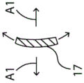
构件40的每个脊17具有扩大的远侧部分46,并且每个脊具有较宽的近侧端部和较窄的远侧端部。在一些实施方案中,如图5A、图5B、图5C、图5D和图5E所示,脊是线性渐缩的,以获得沿其长度变化的“平面外”柔韧性(参见图5E中的箭头A1),包括朝远侧端部48增加的柔韧性。在一些实施方案中,一个或多个脊17具有:具有均匀宽度W1的近侧部分17P,具有由锥度线T1限定的连续的线性锥度的远侧部分17D1(参见图5B),以及具有小于W1的均匀宽度W2的更远侧部分17D2。远侧部分17D1具有连续逐渐增加的柔韧性,使得当远侧部分46与组织发生接触时,脊可以采用预定的形式或曲率。所得的具有相对更刚性的近侧部分和相对更柔性的远侧部分的脊有助于防止脊在使用期间彼此交叉和重叠。Each
在一些实施方案中,一个或多个脊17在端部41与端部46之间具有不连续的线性锥度,如图6A、图6B、图6C、图6D、图6E、图6F和图6G中所示。不连续的线性锥度包括一个或多个较窄部分或凹入部分50,这些部分策略性地沿脊定位以中断由杆42与扩大的远侧部分46之间的锥度T2限定的其他连续的线性锥度。每个凹入部分50具有宽度W(参见图6C),该宽度W小于更远侧部分的宽度WD并且还小于更近侧部分的宽度WP,其中宽度WD<宽度WP。因此,每个凹入部分50有利地允许脊的该区域具有与脊的紧邻(远侧和近侧)部分51不同的柔性,并且在由凹入部分50分隔开的部分之间提供一定程度的独立柔韧性(参见图6B)。因此,当远侧部分46与组织发生接触时,这些脊被允许在凹入部分50的该区域中相对于脊的部分51展现明显更大的柔韧性,因此展现更紧密或更锐利的曲率。In some embodiments, one or
在一些实施方案中,每个脊(在杆42的远侧端部与脊的远侧端部之间)具有介于约1.0cm至2.5cm之间、或介于约1.50cm与2.0cm之间的范围内的长度,和介于约0.009英寸与0.02英寸之间的范围内的宽度。在一些实施方案中,凹入部分50具有介于脊的长度的约10%至20%之间的范围内的长度,以及介于紧邻宽度的约50%至80%之间的范围内的宽度W,从杆42的远侧端部开始测量,该凹入部分的近侧前缘位于脊的长度的约55%至65%处。In some embodiments, each ridge (between the distal end of
为了进一步促进微电极沿脊的整个长度与组织接触,每个脊17具有预成形的构型或曲率,该预成形的构型或曲率通过例如加热和模制夹具来实现。一个或多个脊17具有至少两个不同的预成形曲率C1和C2,如图7A所示,其中具有预成形曲率C1的区段S1由半径R1限定,并且具有预成形曲率C2的区段S2由半径R2限定,其中半径R1<R2并且曲率C1和C2大致在彼此相反的方向上,使得一体式支撑构件40的脊具有类似于打开的伞的大致面向前方的凹面。如图7B所示(为了清楚起见仅示出了两个脊),当脊的远侧端部与例示性表面SF发生接触时,预成形的脊从它们的中立构型N(以虚线示出)转变为它们的适应性或暂时“变形”构型A,该构型A可以包括可以更适于心脏组织的具有波状起伏的区域的“蹲伏”轮廓(与它们的中立构型相比)。有利地,一体式支撑构件40保持其大致面向前的凹面构型,而不会在组织接触时由内向外翻出(就像在强风中向上翻转的伞)。To further facilitate contact of the microelectrodes with tissue along the entire length of the ridges, each
在一些实施方案中,一个或多个脊17至少具有曲线区段和线性区段。在一些实施方案中,一个或多个脊沿其长度具有至少两个不同的预成形曲率。例如,如图8A所示,一个或多个脊17具有第一区段SA、第二区段SB和第三区段SC,其中第一区段SA具有由半径RA限定的预成形曲率CA,第二区段SB具有由半径RB限定的预成形曲率CB,并且第三区段SC是线性的,其中半径RA<半径RB。如图8B所示(为了清楚起见仅示出了两个脊),当脊的远侧端部与例示性表面SF发生接触时,预成形的脊从它们的中立构型N转变为它们的适应性或暂时“变形”构型A,该构型A可以包括可以更适于心脏组织的具有凸面的区域的更深的凹面(与它们的中立构型相比)。In some embodiments, the one or
作为另一个示例,如图9A所示,一个或多个脊17D具有第一区段SJ、第二区段SK和第三区段SL,其中第一区段SJ具有由半径RJ限定的预成形曲率CJ,第二区段SK是线性的,并且第三区段SL具有由半径RL限定的预成形曲率CL,其中半径RJ<半径RL。如图9B所示(为了清楚起见仅示出了两个脊),当脊的远侧端部与例示性表面SF发生接触时,预成形的脊从它们的中立构型N转变为它们的适应性或暂时“变形”构型A,该构型A可以包括可以更适于心脏组织的较平坦区域的较低轮廓(与它们的中立构型相比)。As another example, as shown in FIG. 9A, one or
参考图10,在一些实施方案中,一体式支撑构件40及其脊17可以由多个参数限定,包括例如以下参数:10, in some embodiments, the
a=第二曲率的高度,介于约0.00英寸与0.050英寸之间的范围内a = height of second curvature, in the range between about 0.00 inches and 0.050 inches
b=第二曲率的远侧长度,介于约0.302英寸与0.694英寸之间的范围内b = distal length of the second curvature, in the range between about 0.302 inches and 0.694 inches
c=第二曲率的近侧长度,介于约0.00英寸与0.302英寸之间的范围内c=proximal length of second curvature in the range between about 0.00 inches and 0.302 inches
d=第一曲率与第二曲率之间的距离,介于约0.00英寸与0.170英寸之间的范围内d = distance between first curvature and second curvature, in the range between about 0.00 inches and 0.170 inches
e=第一曲率半径,介于约0.075英寸与0.100英寸之间的范围内e = first radius of curvature, in the range between about 0.075 inches and 0.100 inches
f=具有均匀宽度的区段的长度,约0.100英寸f = length of segment with uniform width, about 0.100 inches
g=凹面深度,介于约0.123英寸与0.590英寸之间的范围内g = depth of concave, in the range between about 0.123 inches and 0.590 inches
值得注意的是,在一体式支撑构件40的一些实施方案中,近侧(或第一)预成形曲率与远侧(或第二)预成形曲率相反,使得远侧电极组件15的脊17可以在组织接触时维持其大致的凹面并保持面向前方,而不反转,同时高度柔性的脊允许该组件具有可挠性或“伸展性”,这防止脊的远侧尖端在接触组织时以及当远侧电极组件被压向组织表面以确保由脊17中的每一个脊接触组织时刺穿组织或以其他方式对组织造成损伤。此外,在一些实施方案中,凹入部分50可以在近侧预成形曲率与远侧预成形曲率之间跨越,使得脊的三个部分(近侧部分、凹入部分和远侧部分)中的每一者可以响应于组织接触和由导管的操作使用者施加的相关联压力而作出不同的表现并且在柔韧性方面相对于彼此具有一定程度的独立性。Notably, in some embodiments of the
应当理解,为了便于讨论和解释,前述附图展示了脊的夸大的变形和曲率,而实际的变形和曲率可能细微得多并且不那么敏锐。It should be understood that, for ease of discussion and explanation, the foregoing figures show exaggerated deformations and curvatures of the ridges, while actual deformations and curvatures may be much subtler and less acute.
在一些实施方案中,一个或多个脊17还被构造为具有铰链90,用于平面内(从一侧到另一侧)偏转。如图11A和图11B所示,脊17可以具有多个沿相对的横向边缘的凹口或凹槽,包括沿一个边缘85a的可膨胀凹槽80(例如,为狭缝81和圆形开口82的形式)和沿相对的边缘85b的可压缩凹槽83(例如,为狭槽84和圆形开口82的形式),从而形成用于沿这些边缘的更多平面内偏转的铰链90。在图11A和图11B的实施方案中,朝向脊17的边缘85b发生单向偏转。然而,应当理解,在沿边缘85a和边缘85b这两者形成可压缩凹槽83的情况下,脊17具有朝边缘85a或85b中的任一者的双向偏转。合适的铰链在美国专利号7276062中有所描述,该专利的全部内容以引用方式并入本文。In some embodiments, one or
如图12A和图12B所示,远侧电极组件15的每个脊17沿其长度由非导电脊覆盖件或管28围绕。在一些实施方案中,非导电脊覆盖件28包括非常柔软且高度柔性的生物相容性塑料,诸如PEBAX或PELLATHANE,并且脊覆盖件28安装在脊上,其长度与脊一起在杆42与扩大的远侧部分46之间共同延伸。脊覆盖件28的合适的构造材料是足够柔软和柔性的,以便通常不妨碍脊17的柔韧性。As shown in Figures 12A and 12B, each
在一些实施方案中,每个被覆盖的脊17沿其长度具有小于3弗伦奇的直径D,优选地小于2.7弗伦奇的直径,以及更优选地为2弗伦奇的直径(例如,介于约0.025英寸与0.035英寸之间的直径)。In some embodiments, each covered
每个脊17包括封装扩大的远侧部分46的非创伤性远侧覆盖件或帽45(参见图12A)。在一些实施方案中,覆盖件45包括生物相容性粘合剂或密封剂,诸如聚氨酯,该生物相容性粘合剂或密封剂具有球根状构型,以最小化在接触组织或抵靠组织施加压力时对组织的损伤。覆盖件45的构造包括粘合剂或密封剂的桥接部分63,该桥接部分穿过扩大的远侧部分46中的通孔47并有利地形成将覆盖件45固定在远侧部分46上的机械锁,并使覆盖件45从扩大的远侧部分46分离的风险最小化。Each
每个脊17都承载多个微电极18。微电极的数量和布置可以根据预期用途而变化。在一些实施方案中,“多个”在介于约48与72之间的范围内,但是应当理解,“多个”可以更大或更小。在一些实施方案中,每个微电极具有小于800μm(例如,介于约600μm与300μm之间的范围内,并且例如,测得为约480μm、460μm或约450μm)的长度L。在一些实施方案中,远侧电极组件15具有大于约7.1/cm2(例如,介于约7.2/cm2与12.6/cm2之间的范围内)的面积覆盖率。在一些实施方案中,远侧电极组件15具有大于约2.5个微电极/cm2(例如,介于约4个微电极/cm2与7个微电极/cm2之间的范围内)的微电极密度。Each
在一些实施方案中,远侧电极组件15具有八个脊,每个脊的长度为约1.5cm并且承载八个微电极,总共48个微电极,每个脊的微电极具有约460μm的长度,其中组件15具有约7.1/cm2的面积覆盖率,和约7个微电极/cm2的微电极密度。In some embodiments, the
在一些实施方案中,远侧电极组件15具有八个脊,每个脊的长度为约2.0cm并且承载六个微电极,总共48个微电极,每个脊的微电极具有约460μm的长度,其中组件15具有约12.6/cm2的面积覆盖率,和约4个微电极/cm2的微电极密度。In some embodiments, the
脊17上的微电极18可以作为单极或双极被布置为在它们之间具有多种间距,其中间距被测得为相邻微电极或微电极对的相应前缘之间的间隔。作为单极,微电极18可以被分隔开介于约1mm与3mm之间的范围内的距离S1,参考图12A。作为双极,相邻的成对微电极18可以被分隔开介于1mm与6mm之间的范围内的距离S2,参考图12B。The
在一些实施方案中,参考图12B,六个微电极被布置为三个双极对,双极对的近侧边缘之间的间距S1为2.0mm,且相邻双极对的近侧边缘之间的间距S2为6.0mm,这三个双极对通常可以称为“2-6-2”构型。称为“2-5-2-5-2”构型的另一个构型具有三个双极对,其中双极对的近侧边缘之间的间距S1为2.0mm,且相邻双极对的近侧边缘之间的间距S2为5.0mm。In some embodiments, referring to FIG. 12B , six microelectrodes are arranged in three bipolar pairs, the spacing S1 between the proximal edges of the bipolar pairs is 2.0 mm, and the distance between the proximal edges of adjacent bipolar pairs is 2.0 mm. The spacing S2 between them is 6.0 mm, and these three bipolar pairs can generally be referred to as a "2-6-2" configuration. Another configuration, referred to as the "2-5-2-5-2" configuration, has three bipolar pairs, where the spacing S1 between the proximal edges of the bipolar pairs is 2.0 mm, and adjacent bipolar pairs are The spacing S2 between the proximal edges is 5.0mm.
在一些实施方案中,参考图12A,六个微电极被布置为单极,其中相邻单极的近侧边缘之间的间距S1为2.0mm,所述单极可以称为“2-2-2-2-2”构型。在一些实施方案中,间距S1为约3.0mm,因此被称为“3-3-3-3-3”构型。In some embodiments, referring to FIG. 12A, six microelectrodes are arranged as monopoles, wherein the spacing S1 between the proximal edges of adjacent monopoles is 2.0 mm, which monopoles may be referred to as "2-2- 2-2-2" configuration. In some embodiments, the spacing S1 is about 3.0 mm, hence the term "3-3-3-3-3" configuration.
在一些实施方案中,每个脊的最近侧微电极18P被承载在脊上与相邻脊的最近侧微电极18P不同的位置处。如图13所示,尽管在任一个脊上的微电极之间的间距在整个远侧电极组件中可以是均匀的,但沿任一个脊的微电极相对于沿相邻脊的微电极交错(或偏移)。例如,对于脊17A、17C、17E和17G,最近侧微电极18P与杆42的端部之间的距离D1大于对于脊17B、17D、17G和17G,最近侧电极18P与杆42的端部之间的距离D2。这种交错构型使相邻脊上的微电极碰触和短路的风险最小化,尤其是当操作者抵靠组织扫过远侧电极组件时。此外,这种交错构型提供了远侧电极组件15的更大的有效接触表面,因为有效的同心电极阵列被加倍了(参见图13)。参考图13、图26和图27,交错可以根据包括任一个脊上的相邻电极之间的距离或间距在内的因素而呈现不同的构型。在一些实施方案中,每个脊可以呈现独特的交错构型(图27)。在一些实施方案中,一个或多个脊可以呈现相同的交错构型,只要这些脊彼此不相邻并且被具有不同交错构型的至少一个或多个脊分隔开即可(参见例如图26中的同心度C1、C2、C3和C4)。就这一点而言,沿任一个脊的相邻电极之间的间距可以是不均匀的,只要沿相邻脊的相邻电极之间的间距不同并且相邻脊的电极位于不同的同心度上即可。交错构型还包括任一个脊的电极围绕组件15的纵向轴线的同心迹线不同于任何相邻脊的电极的同心迹线的构型。In some embodiments, the
在美国专利号7089045、7155270、7228164和7302285中描述了远侧电极组件与偏转节段14的远端部分之间的接合部的构造和组件的部件,这些专利的全部公开内容以引用方式并入本文。如图14A所示,一体式支撑构件40的杆42接纳偏转节段14的多管腔管30的变窄的远侧端部30D。非导电套筒68在周向上围绕杆42,该非导电套筒在杆的近侧端部与远侧端部之间与杆共同延伸。套筒68的远侧端部68D在非导电脊管28的近侧端部28P上延伸,以便有助于将管28固定在脊17上。The configuration of the interface between the distal electrode assembly and the distal portion of the
远侧端部30D的近侧是外壳插入件60,该外壳插入件也被接纳和定位在一体式支撑构件40的杆42的管腔43中。外壳插入件60在纵向方向上的长度短于杆42的长度,使得该外壳插入件不会突出超过杆42的远侧端部。外壳插入件60被构造为具有一个或多个管腔。一个管腔71可以具有非圆形横截面,例如,大致类似于“C”或细长芸豆的横截面,并且另一个管腔72可以具有圆形横截面,如图14B所示,使得这些管腔可以彼此嵌套以最大化这些管腔的大小并增加外壳插入件60内的空间效率。穿过更多管腔71的部件不会被限制在任一个位置或方位,因此具有更大的移动自由度和更小的断裂风险,尤其是当导管的区段被扭转并且部件被扭曲时。Proximal of the
在一些实施方案中,电磁位置传感器26(在缆线24的远侧端部处)被接纳在管腔72中。其他部件包括例如冲洗管27和用于远侧电极组件15上的微电极18的引线22(以及用于脊17近侧的任何环形电极67、69和70的引线25)穿过管腔71。就这一点而言,外壳插入件60提供多种功能,包括将各种部件对准并定位在一体式支撑构件40的杆42内;提供用于这些各种部件的间隔和这些部件之间的分隔,并且用作机械锁,该机械锁增强偏转节段14的远侧端部与远侧电极组件15之间的接合部。在后一种情况下,在导管的组装和使用期间,接合部可能受到多种力的作用,这些力可能扭转或拉动该接合部。例如,扭转力可能夹紧冲洗管27以阻止流动,或者导致引线22和25断裂。为此,该接合部有利地与外壳插入件60组装成一种构型以形成机械锁,如下文解释的。In some embodiments, electromagnetic position sensor 26 (at the distal end of cable 24 ) is received in
外壳插入件60可以选择性地被构造为具有比杆42的管腔43的内周长小预定量的外径。这在管腔43中产生了可察觉的空隙,该空隙填充有合适的粘合剂61,诸如聚氨酯,以将外壳插入件60牢固地附连在管腔43的内部并且附连到多管腔管30的远侧端部,以便最小化(如果不是防止的话)插入件60与杆42之间的相对移动。外壳插入件60保护其围绕的部件,包括电磁位置传感器26(及其与缆线24的附接)、冲洗管27以及引线22和25,并且提供杆42附接到其上的更大和更刚性的结构。为此,外壳插入件60甚至可以具有非圆形/多边形的外部横截面和/或纹理化表面,以改善外壳插入件60与粘合剂61之间的附连。The
为了便于将粘合剂施加到空隙中,杆42在其侧壁中在下述位置处形成有开口65:该位置允许在外壳插入件60已经被插入到杆42的管腔43中之后为该外壳插入件提供视觉和机械通路。在组装该接合部期间,通过开口65提供对管腔43和其中的部件的视觉检查。尽管施加到插入到管腔43中之前的外壳插入件60的外表面的任何粘合剂可能在插入期间从杆42喷出,但是附加的粘合剂可以有利地通过开口65施加到管腔43中以填充空隙,并且因此将外壳插入件60牢固地附连到杆42和多管腔管30的远端部分。外壳插入件60和其空间容纳管腔71的组合在远侧电极组件15与偏转节段14之间提供了更整合且更不易受损的接合部。To facilitate application of the adhesive into the void, the
在一些实施方案中,导管10包括冲洗管27,该冲洗管的远侧端部27D通常与一体式支撑构件40的杆42的远侧端部共同延伸。因此,冲洗流体(例如盐水)从远程流体源递送到远侧电极组件15,该远程流体源经由鲁尔接口100(图1)经由延伸穿过控制手柄16的冲洗管27、导管主体12的中心管腔19(图2)和偏转节段14的管30的管腔31E(图3)提供冲洗流体,在这种情况下,冲洗流体在一体式支撑构件40的杆42的远侧端部处离开冲洗管27的远侧端部,如图15A和图25所示。合适的粘合剂(诸如聚氨酯)围绕冲洗管27的远侧端部堵塞并密封管腔43。在一些实施方案中,导管没有冲洗,并且一体式支撑构件40的杆42的远侧端部被粘合剂或密封剂90(诸如聚氨酯)整体密封,如图14A所示。In some embodiments,
图16示出了一个实施方案,其中非导电脊管28包括增强的拉伸构件53。如本领域普通技术人员所理解的,微电极18安装在脊覆盖件或管28上,其中细长的管状芯轴(未示出)定位在脊覆盖件28的管腔中,以在微电极18旋转型锻到脊覆盖件28上时支撑这些微电极。微电极18可以具有圆形横截面,包括圆形或椭圆形的构型。为了防止或至少最小化型锻期间微电极18和脊覆盖件28的不期望的变形,包括在纵向方向上的伸长,其上承载和型锻微电极的脊覆盖件28包括增强的拉伸构件53,如图16所示。拉伸构件53(例如线材或纤维(在本文可互换使用))嵌入在(例如在挤出拉伸构件期间)管的侧壁54中。拉伸构件53可以单轴或编织图案嵌入在非导电覆盖件挤出物中,在纵向方向上延伸或至少具有在纵向方向上延伸的部分。因此,拉伸构件用于抵抗特别柔软和柔性的脊覆盖件28和微电极18在纵向方向上的不期望的伸长。合适的拉伸构件的示例包括VECTRAN、DACRON、KEVLAR或其他具有低伸长特性的材料。多个增强拉伸构件并非关键因素。在一些实施方案中,“多个”可以在介于以径向等值构型布置的两个与六个之间的范围内。在例示的实施方案中,脊覆盖件28包括围绕侧壁54成0度、90度、180度和270度的四个拉伸构件。FIG. 16 shows an embodiment in which the
在一些实施方案中,拉伸构件53的远侧端部锚固在封装脊17的扩大的远侧部分的球根状覆盖件45中,并且/或者环99D(如图16所示)可以被压缩或夹紧在脊覆盖件28和脊17上。在一些实施方案中,拉伸构件53的近侧端部与脊覆盖件28的近侧端部共同延伸,并且也可以通过环99P锚固(参见图14A和图15A)。In some embodiments, the distal end of
在一些实施方案中,拉伸构件53具有大得多的长度。参考图17、图18、图19和图20,拉伸构件53延伸穿过形成在一体式支撑构件40的杆42中的开口44并延伸到杆42的管腔43中。拉伸构件53然后延伸穿过外壳插入件60的管腔71、偏转节段14的管30的管腔31F和导管主体12的中心管腔19,并延伸到控制手柄16中。拉伸构件53的近侧端部被构造用于被操作者操纵,以使远侧电极组件15的脊17偏转,使得它们可以单独地用作“手指”。就这一点而言,拉伸构件可以允许相对于管28纵向移动的方式形成在管28的侧壁中,使得任何一个或多个拉伸构件可以被朝近侧拉动,以使相应的脊朝向那些拉伸构件沿其延伸的一侧弯曲或偏转。因此,操作者能够根据需要或期望来操纵一个或多个脊以进行单独的偏转,包括当远侧电极组件与不平坦的组织表面接触时,在这种情况下一个或多个脊需要进行调整以更好地进行组织接触。In some embodiments,
参考图21、图22、图23和图24,示出了本发明的导管10在心脏的所有四个腔室(即,左心房和右心房,左心室和右心室)中使用,其中远侧电极组件15的脊容易适应并顺应于心脏组织解剖结构(包括例如在肺静脉的内部,以及在右心房的后壁,左右心室的前壁、下壁和/或侧壁上,以及心尖)的各种轮廓和表面。不管表面的解剖结构是怎样的,脊的预成形构型均有利地促进了脊上承载的微电极与组织之间的接触。21, 22, 23, and 24, the
在一些实施方案中,导管10在远侧电极组件15的近侧具有多个环形电极。除了环形电极67之外,如图1所示,导管还承载比环形电极67更近侧的另一个环形电极69,以及比环形电极69更近侧的另一个环形电极70。为这些环形电极提供引线25。在一些实施方案中,环形电极69位于偏转区段14的多管腔管30的远侧端部30D附近,并且环形电极70与环形电极69隔开介于约1mm与3mm之间的范围内的距离S。相应的引线25经由形成在一体式支撑构件40的杆42中和套筒68中的开口75连接到环形电极67。用于环形电极69和70的相应引线25连接到形成在偏转节段14的管30的这些侧壁中的通路开口(未示出)。In some embodiments,
牵拉线23A和23B的延伸穿过导管主体12的每个部分在周向上被相应的压缩线圈101A和101B围绕,如本领域中所理解的。牵拉线23A和23B的延伸穿过偏转节段的多管腔管30的每个部分在周向上被护套围绕,该护套保护牵拉线,使牵拉线在偏转时不会切入管中。如本领域中所理解的,牵拉线的远侧端部可以在管30的远侧端部处或附近锚固在管30的侧壁中。如本领域中所理解的,牵拉线的近侧端部锚固在控制手柄16中,以便由导管的操作者致动。Each portion of
已参考本发明的当前优选实施方案来呈现前述描述。本发明所属技术领域内的技术人员将会知道,在不有意脱离本发明的原则、实质和范围的前提下,可对所述结构作出更改和修改。在一个实施方案中公开的任何特征或结构可根据需要或适当情况并入以代替或补充任何其他实施方案的其他特征。如本领域的普通技术人员所理解的,附图未必按比例绘制。因此,上述的具体实施方式不应当解读为仅适合附图所述和所示的精密结构,而是应当解读为符合下述的权利要求并且支持下述的权利要求,下述的权利要求具有本发明的充分和公平的范围。The foregoing description has been presented with reference to presently preferred embodiments of the invention. Those skilled in the art to which this invention pertains will appreciate that changes and modifications to the described structures can be made without intentionally departing from the spirit, spirit and scope of this invention. Any feature or structure disclosed in one embodiment may be incorporated as needed or appropriate in place of or in addition to other features of any other embodiment. As will be understood by those of ordinary skill in the art, the figures are not necessarily drawn to scale. Therefore, the above-described detailed description should not be construed as being suitable only for the precise structures described and illustrated in the accompanying drawings, but should be construed in accordance with and in support of the following claims, which have the present Full and equitable scope of the invention.
Claims (20)
Applications Claiming Priority (3)
| Application Number | Priority Date | Filing Date | Title |
|---|---|---|---|
| US15/890309 | 2018-02-06 | ||
| US15/890,309 US10945626B2 (en) | 2018-02-06 | 2018-02-06 | Catheter with staggered electrodes spine assembly |
| PCT/US2019/016580 WO2019156945A1 (en) | 2018-02-06 | 2019-02-05 | Catheter with staggered electrodes spine assembly |
Publications (2)
| Publication Number | Publication Date |
|---|---|
| CN111918606A true CN111918606A (en) | 2020-11-10 |
| CN111918606B CN111918606B (en) | 2025-01-24 |
Family
ID=65496983
Family Applications (1)
| Application Number | Title | Priority Date | Filing Date |
|---|---|---|---|
| CN201980012089.4A Active CN111918606B (en) | 2018-02-06 | 2019-02-05 | Catheter with staggered electrode ridge assembly |
Country Status (6)
| Country | Link |
|---|---|
| US (2) | US10945626B2 (en) |
| EP (1) | EP3749192A1 (en) |
| JP (1) | JP7317862B2 (en) |
| CN (1) | CN111918606B (en) |
| IL (1) | IL276504B2 (en) |
| WO (1) | WO2019156945A1 (en) |
Cited By (1)
| Publication number | Priority date | Publication date | Assignee | Title |
|---|---|---|---|---|
| CN114831726A (en) * | 2022-04-20 | 2022-08-02 | 苏州中荟医疗科技有限公司 | Ablation device |
Families Citing this family (10)
| Publication number | Priority date | Publication date | Assignee | Title |
|---|---|---|---|---|
| JP7499702B2 (en) | 2018-05-21 | 2024-06-14 | セント・ジュード・メディカル,カーディオロジー・ディヴィジョン,インコーポレイテッド | Radiofrequency Ablation and Direct Current Electroporation Catheters |
| US12156979B2 (en) | 2018-05-21 | 2024-12-03 | St. Jude Medical, Cardiology Division, Inc. | Deflectable catheter shaft with pullwire anchor feature |
| US20210244360A1 (en) * | 2018-06-07 | 2021-08-12 | St. Jude Medical, Cardiology Division, Inc. | Sensing, mapping, and therapy catheter with multiple catheterlets |
| US11642063B2 (en) | 2018-08-23 | 2023-05-09 | St. Jude Medical, Cardiology Division, Inc. | Curved high density electrode mapping catheter |
| CN112368747A (en) * | 2018-09-10 | 2021-02-12 | 圣犹达医疗用品心脏病学部门有限公司 | System and method for displaying electrophysiological signals from a multi-dimensional catheter |
| US12082936B2 (en) | 2018-09-27 | 2024-09-10 | St. Jude Medical, Cardiology Division, Inc. | Uniform mapping balloon |
| US11918762B2 (en) | 2018-10-03 | 2024-03-05 | St. Jude Medical, Cardiology Division, Inc. | Reduced actuation force electrophysiology catheter handle |
| US11219398B2 (en) | 2019-03-07 | 2022-01-11 | Biosense Webster (Israel) Ltd. | Device, system and use of a catheter system to record and map cardiac rhythm |
| US12263014B2 (en) | 2020-08-18 | 2025-04-01 | St. Jude Medical, Cardiology Division, Inc. | High-density electrode catheters with magnetic position tracking |
| US11771373B2 (en) | 2020-11-09 | 2023-10-03 | Biosense Webster (Israel) Ltd. | Staggered electrode arrangements for electrophysiological sensing |
Citations (17)
| Publication number | Priority date | Publication date | Assignee | Title |
|---|---|---|---|---|
| CN101094622A (en) * | 2003-09-18 | 2007-12-26 | 先进生物假体表面有限公司 | Medical devices having mems functionality and methods of making same |
| US20100168737A1 (en) * | 2008-12-30 | 2010-07-01 | Debby Esther Grunewald | Catheter with multiple electrode assemblies for use at or near tubular regions of the heart |
| US20110077660A1 (en) * | 2008-03-06 | 2011-03-31 | Janik John J | Foldable, implantable electrode assembly and tool for implanting same |
| CN102892453A (en) * | 2010-03-12 | 2013-01-23 | 圣犹达医疗用品电生理部门有限公司 | Magnetically guided catheter |
| CN103315806A (en) * | 2012-03-21 | 2013-09-25 | 韦伯斯特生物官能(以色列)有限公司 | Flower catheter for mapping and ablating veinous and other tubular locations |
| US20140194716A1 (en) * | 2013-01-08 | 2014-07-10 | Biosense Webster (Israel), Ltd. | Catheter with multiple spines of different lengths arranged in one or more distal assemblies |
| US20140271039A1 (en) * | 2013-03-15 | 2014-09-18 | Pcc Structurals, Inc. | Blind, bulbing, tacking rivet and method of installation |
| US20150209102A1 (en) * | 2014-01-24 | 2015-07-30 | Gyrus Medical Limited | Surgical instrument |
| US20150245912A1 (en) * | 2012-09-21 | 2015-09-03 | Waldemar Link Gmbh & Co. Kg | Joint Implant |
| CN105358070A (en) * | 2013-02-08 | 2016-02-24 | 阿库图森医疗有限公司 | Expandable catheter assembly with flexible printed circuit board |
| US20160143588A1 (en) * | 2014-11-20 | 2016-05-26 | Biosense Webster (Israel) Ltd. | Catheter with high density electrode spine array |
| CN105828866A (en) * | 2013-12-10 | 2016-08-03 | 圣犹达医疗用品电生理部门有限公司 | Catheter curve shape strut |
| US20160374582A1 (en) * | 2015-06-29 | 2016-12-29 | Biosense Webster (Israel) Ltd. | Catheter with stacked spine electrode assembly |
| CN106510698A (en) * | 2015-09-14 | 2017-03-22 | 韦伯斯特生物官能(以色列)有限公司 | Dual multiray electrode catheter |
| CN106852690A (en) * | 2015-12-09 | 2017-06-16 | 韦伯斯特生物官能(以色列)有限公司 | The many ray electrode catheters of binode |
| CN106923815A (en) * | 2015-10-08 | 2017-07-07 | 韦伯斯特生物官能(以色列)有限公司 | Conduit with the membrane type ridge for pulmonary vein isolation |
| CN107041744A (en) * | 2016-02-08 | 2017-08-15 | 韦伯斯特生物官能(以色列)有限公司 | The conduit ridge component of Miniature double-pole electrode with tight spacing |
Family Cites Families (25)
| Publication number | Priority date | Publication date | Assignee | Title |
|---|---|---|---|---|
| US5782239A (en) * | 1992-06-30 | 1998-07-21 | Cordis Webster, Inc. | Unique electrode configurations for cardiovascular electrode catheter with built-in deflection method and central puller wire |
| US7089045B2 (en) | 2002-08-30 | 2006-08-08 | Biosense Webster, Inc. | Catheter and method for mapping Purkinje fibers |
| US7027851B2 (en) * | 2002-10-30 | 2006-04-11 | Biosense Webster, Inc. | Multi-tip steerable catheter |
| US7276062B2 (en) | 2003-03-12 | 2007-10-02 | Biosence Webster, Inc. | Deflectable catheter with hinge |
| US7179256B2 (en) * | 2003-10-24 | 2007-02-20 | Biosense Webster, Inc. | Catheter with ablation needle and mapping assembly |
| US7155270B2 (en) | 2003-10-24 | 2006-12-26 | Biosense Webster, Inc. | Catheter with multi-spine mapping assembly |
| US7150745B2 (en) * | 2004-01-09 | 2006-12-19 | Barrx Medical, Inc. | Devices and methods for treatment of luminal tissue |
| US7524318B2 (en) | 2004-10-28 | 2009-04-28 | Boston Scientific Scimed, Inc. | Ablation probe with flared electrodes |
| US8870863B2 (en) | 2010-04-26 | 2014-10-28 | Medtronic Ardian Luxembourg S.A.R.L. | Catheter apparatuses, systems, and methods for renal neuromodulation |
| WO2012151396A2 (en) | 2011-05-03 | 2012-11-08 | Shifamed Holdings, Llc | Steerable delivery sheaths |
| EP2739336A2 (en) | 2011-08-04 | 2014-06-11 | Kings College London | Continuum manipulator |
| US8825130B2 (en) * | 2011-12-30 | 2014-09-02 | St. Jude Medical, Atrial Fibrillation Division, Inc. | Electrode support structure assemblies |
| US9474486B2 (en) * | 2013-03-08 | 2016-10-25 | St. Jude Medical, Atrial Fibrillation Division, Inc. | Basket for a multi-electrode array catheter |
| US9204929B2 (en) * | 2013-09-16 | 2015-12-08 | Biosense Webster (Israel) Ltd. | Basket catheter with deflectable spine |
| WO2015057521A1 (en) * | 2013-10-14 | 2015-04-23 | Boston Scientific Scimed, Inc. | High resolution cardiac mapping electrode array catheter |
| US10105073B2 (en) * | 2013-11-21 | 2018-10-23 | Biosense Webster (Israel) Ltd | Flexible multiple-arm diagnostic catheter |
| WO2015095629A1 (en) * | 2013-12-20 | 2015-06-25 | The Johns Hopkins University | Method and apparatus for selective treatiment inside a body lumen |
| US9795315B2 (en) * | 2014-01-28 | 2017-10-24 | John Bullinga | Catheter system for mapping of the left atrium, right atrium and coronary sinus |
| WO2015187430A2 (en) * | 2014-06-04 | 2015-12-10 | Boston Scientific Scimed, Inc. | Electrode assembly |
| US9782099B2 (en) | 2014-12-31 | 2017-10-10 | Biosense Webster (Israel) Ltd. | Basket catheter with improved spine flexibility |
| US10080600B2 (en) | 2015-01-21 | 2018-09-25 | Covidien Lp | Monopolar electrode with suction ability for CABG surgery |
| CN108472481A (en) * | 2015-10-06 | 2018-08-31 | 哈尔西恩医疗有限公司 | Aortorenal ganglions detects |
| WO2017192712A1 (en) * | 2016-05-03 | 2017-11-09 | St. Jude Medical, Cardiology Division, Inc. | Irrigated high density electrode catheter |
| US10772566B2 (en) * | 2016-05-17 | 2020-09-15 | Biosense Weber (Israel) Ltd. | Multi-electrode catheter spine and method of making the same |
| EP3565459B1 (en) * | 2017-03-02 | 2024-03-27 | St. Jude Medical, Cardiology Division, Inc. | System and method for differentiation of adipose tissue from scar tissue during electrophysiological mapping |
-
2018
- 2018-02-06 US US15/890,309 patent/US10945626B2/en active Active
-
2019
- 2019-02-05 JP JP2020564041A patent/JP7317862B2/en active Active
- 2019-02-05 IL IL276504A patent/IL276504B2/en unknown
- 2019-02-05 EP EP19706338.1A patent/EP3749192A1/en active Pending
- 2019-02-05 WO PCT/US2019/016580 patent/WO2019156945A1/en active IP Right Grant
- 2019-02-05 CN CN201980012089.4A patent/CN111918606B/en active Active
-
2020
- 2020-11-17 US US16/950,764 patent/US20210068693A1/en active Pending
Patent Citations (17)
| Publication number | Priority date | Publication date | Assignee | Title |
|---|---|---|---|---|
| CN101094622A (en) * | 2003-09-18 | 2007-12-26 | 先进生物假体表面有限公司 | Medical devices having mems functionality and methods of making same |
| US20110077660A1 (en) * | 2008-03-06 | 2011-03-31 | Janik John J | Foldable, implantable electrode assembly and tool for implanting same |
| US20100168737A1 (en) * | 2008-12-30 | 2010-07-01 | Debby Esther Grunewald | Catheter with multiple electrode assemblies for use at or near tubular regions of the heart |
| CN102892453A (en) * | 2010-03-12 | 2013-01-23 | 圣犹达医疗用品电生理部门有限公司 | Magnetically guided catheter |
| CN103315806A (en) * | 2012-03-21 | 2013-09-25 | 韦伯斯特生物官能(以色列)有限公司 | Flower catheter for mapping and ablating veinous and other tubular locations |
| US20150245912A1 (en) * | 2012-09-21 | 2015-09-03 | Waldemar Link Gmbh & Co. Kg | Joint Implant |
| US20140194716A1 (en) * | 2013-01-08 | 2014-07-10 | Biosense Webster (Israel), Ltd. | Catheter with multiple spines of different lengths arranged in one or more distal assemblies |
| CN105358070A (en) * | 2013-02-08 | 2016-02-24 | 阿库图森医疗有限公司 | Expandable catheter assembly with flexible printed circuit board |
| US20140271039A1 (en) * | 2013-03-15 | 2014-09-18 | Pcc Structurals, Inc. | Blind, bulbing, tacking rivet and method of installation |
| CN105828866A (en) * | 2013-12-10 | 2016-08-03 | 圣犹达医疗用品电生理部门有限公司 | Catheter curve shape strut |
| US20150209102A1 (en) * | 2014-01-24 | 2015-07-30 | Gyrus Medical Limited | Surgical instrument |
| US20160143588A1 (en) * | 2014-11-20 | 2016-05-26 | Biosense Webster (Israel) Ltd. | Catheter with high density electrode spine array |
| US20160374582A1 (en) * | 2015-06-29 | 2016-12-29 | Biosense Webster (Israel) Ltd. | Catheter with stacked spine electrode assembly |
| CN106510698A (en) * | 2015-09-14 | 2017-03-22 | 韦伯斯特生物官能(以色列)有限公司 | Dual multiray electrode catheter |
| CN106923815A (en) * | 2015-10-08 | 2017-07-07 | 韦伯斯特生物官能(以色列)有限公司 | Conduit with the membrane type ridge for pulmonary vein isolation |
| CN106852690A (en) * | 2015-12-09 | 2017-06-16 | 韦伯斯特生物官能(以色列)有限公司 | The many ray electrode catheters of binode |
| CN107041744A (en) * | 2016-02-08 | 2017-08-15 | 韦伯斯特生物官能(以色列)有限公司 | The conduit ridge component of Miniature double-pole electrode with tight spacing |
Cited By (1)
| Publication number | Priority date | Publication date | Assignee | Title |
|---|---|---|---|---|
| CN114831726A (en) * | 2022-04-20 | 2022-08-02 | 苏州中荟医疗科技有限公司 | Ablation device |
Also Published As
| Publication number | Publication date |
|---|---|
| IL276504A (en) | 2020-09-30 |
| EP3749192A1 (en) | 2020-12-16 |
| JP7317862B2 (en) | 2023-07-31 |
| IL276504B2 (en) | 2023-11-01 |
| CN111918606B (en) | 2025-01-24 |
| JP2021512772A (en) | 2021-05-20 |
| US20210068693A1 (en) | 2021-03-11 |
| US10945626B2 (en) | 2021-03-16 |
| WO2019156945A1 (en) | 2019-08-15 |
| IL276504B1 (en) | 2023-07-01 |
| US20190239765A1 (en) | 2019-08-08 |
Similar Documents
| Publication | Publication Date | Title |
|---|---|---|
| CN111918606B (en) | Catheter with staggered electrode ridge assembly | |
| EP3749177B1 (en) | Catheter with electrode spine assembly having preformed configurations for improved tissue contact | |
| CN107773300B (en) | Catheter with bipolar electrode spacer and related methods | |
| CN111902073B (en) | Catheter having a spine assembly with increased electrode density including a reinforced spine cover | |
| CN106308790B (en) | Catheter with closed electrode assembly with ridges of consistent length | |
| EP3178386B1 (en) | Catheter | |
| US20190239812A1 (en) | Medical Probe with Staggered Microelectrode Configuration | |
| CN112040860B (en) | Medical probe with staggered microelectrode configuration |
Legal Events
| Date | Code | Title | Description |
|---|---|---|---|
| PB01 | Publication | ||
| PB01 | Publication | ||
| SE01 | Entry into force of request for substantive examination | ||
| SE01 | Entry into force of request for substantive examination | ||
| GR01 | Patent grant | ||
| GR01 | Patent grant |