580 California St., Suite 400
San Francisco, CA, 94104

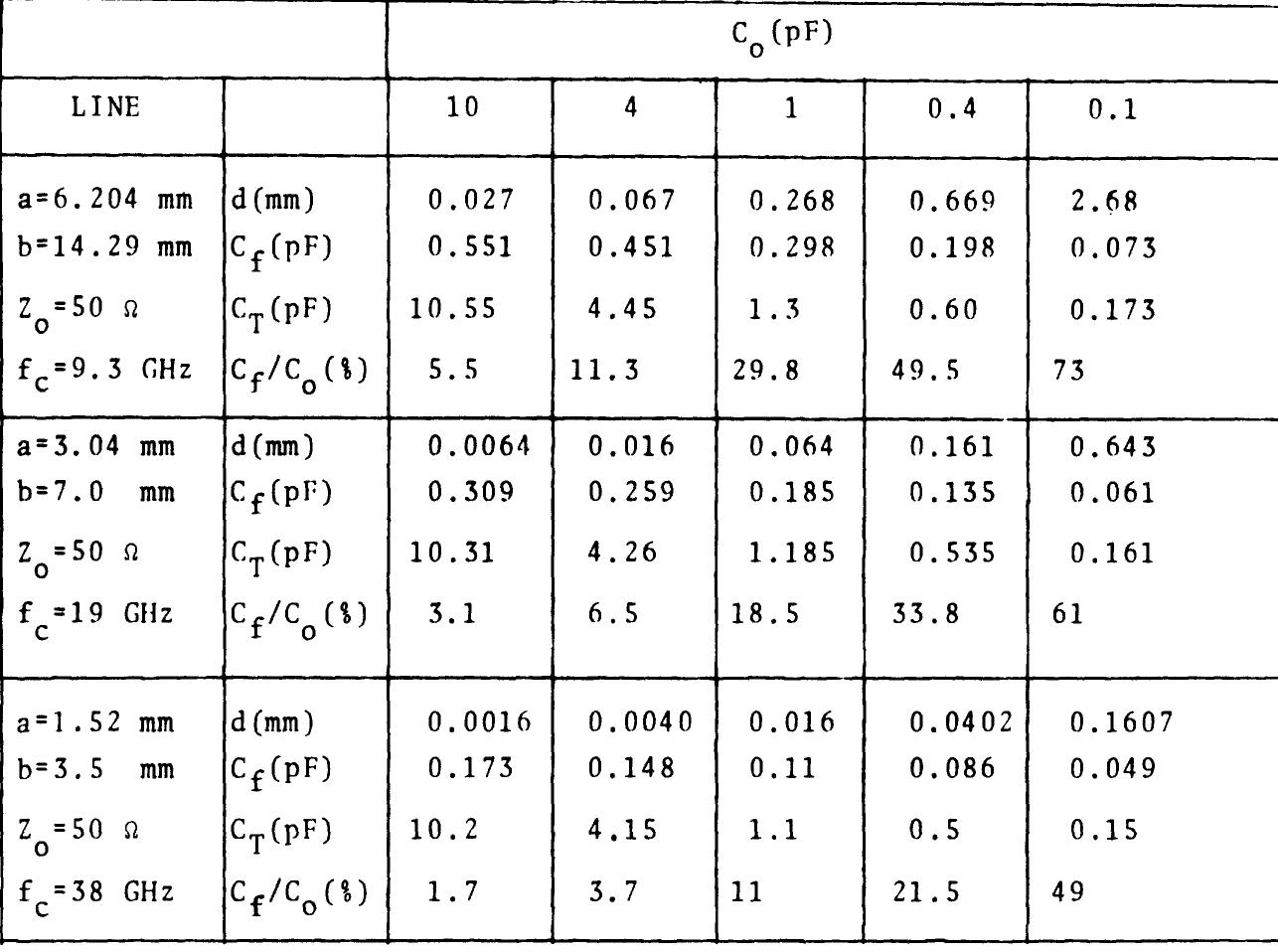
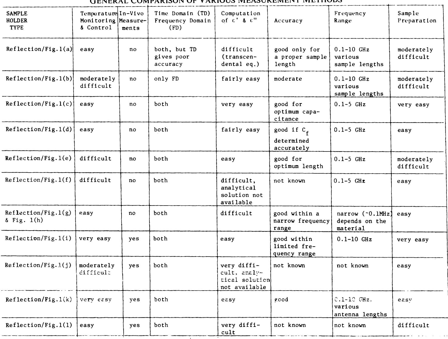
Figure 1 measurement configuration Fig. 1(i), (k), and (1) are suit- able. ——e An equivalent circuit for all the configurations is shown in Fig. 2(a), and its simplified more useful version in (b). Z(e*) represent this part of the impedance terminating the line, which depends on the permittivity of the test sample. Fig. 2(b) applies to all configurations but 1(b). It is applicable when d is small compared to the wavelength. Z or Cy represent the part of impedance which is independent from the dielectric sample. For the configuration shown in Fig. 1(a) Z = ©. The capaci- tance C(e*) in Fig. 2(b) for a lossy dielectric also includes the conductance due to the losses. However, such simplified rep- resentation is convenient for analytical treatment and accurate with restrictions discussed later.