Figure 5 – uploaded by Brijesh Adhikary

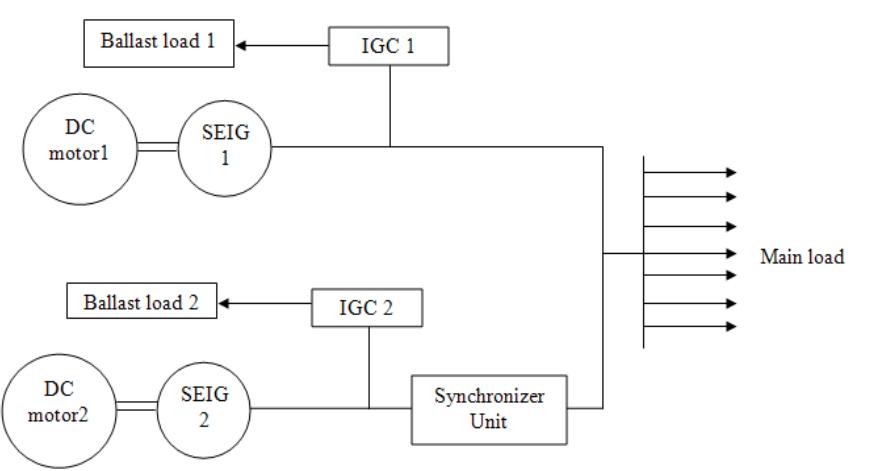
Figure 4 shows the control mechanism of the IGC. Initially the generated voltage is tapped from the line and this voltage is stepped down by transformer and applied to zero crossing detectors. Zero crossing detectors are used for positive half and negative half detection of the input sine wave and produce square waves. These square waves are converted to ramp signal by Ramp Converter. Rectifier (center tapped diode rectifier) rectifies the supply ac voltage to dc voltage. This dec voltage is subtracted by a reference voltage to get the error signal (voltage) using differential amplifier. The subtracted voltage is given to PI Controller. The ramp signal and the erro1 signal from PI Controller are compared by the comparator to give out the pulse signal to the gate of TRIAC for firing. The width of the pulse determines the firing angle of the TRIAC. Thus power to the ballast load is controlled by IGC.


