 Wenkai Wang
580 California St., Suite 400
San Francisco, CA, 94104
Academia.edu no longer supports Internet Explorer.
To browse Academia.edu and the wider internet faster and more securely, please take a few seconds to upgrade your browser.
2019, IEEE Access
https://doi.org/10.1109/ACCESS.2019.2907806…
13 pages
1 file
A novel waverider design methodology is proposed with a variable shock angle based on the osculating cones' theory. The expected shape with special requirements can be generated by arranging the distribution of shock angle using the new method. Contrast investigation is conducted on three waveriders, which are designed with constant, decreasing and increasing shock angle distribution starting from symmetry plane at the average shock angle of 12 •. The feasibility of the proposed approach is validated by the computational fluid dynamics (CFD) simulation. The results show that the distribution of shock angle has a significant influence on the lift-to-drag ratio and volumetric efficiency. Waverider with decreasing shock angle owns the greater volume and volumetric efficiency but with weak aerodynamic performance. The waverider with increasing shock angle has a higher lift-to-drag ratio and enhanced the static stability but with lower volumetric efficiency. The performance of waveriders with variable shock angle under off-design and blunted conditions is also investigated, which reveals a great overall aerodynamic performance and good robustness. INDEX TERMS Hypersonic waverider, variable shock angle, lift-to-drag ratio, off-design condition, bluntness.
2006
In this paper, waverider configurations are generated by specifying an arbitrary conical shockwave shape, and a corresponding leading edge. This inverse design approach makes use of a numerical tool which is based on a semi-analytical approach for solving the Euler equations. In the waverider design space, the aerodynamic figure of merit, (L/D) is considered a function of the shapes of both the conical shockwaves and leading edges. The waverider configuration and aerodynamic performance are considered functions of eight design parameters. The method yields practical vehicle shapes with acceptable volumetric efficiencies. The design method is computationally efficient and permits rapid parametric studies. Several viscous optimized waverider configurations were constructed and their aero performance analyzed. Results show that the waveriders created have acceptable L/D when compared to the Kuchemann Barrier, at times crossing it.
Acta Astronautica, 2011
Angle of attack Angle of the sideslip Mach number a b s t r a c t
2005
This paper describes the design and analysis of scramjets integrated onto waveriderderived hypersonic vehicle configurations. The hypersonic vehicle configurations of interest to this study are derived from prescribed Two-Dimensional shock waves. Through the coupled use of the exact solutions of shock waves in an ideal gas, and the exact representations of planar geometric shapes, a series of elementary configurations are pieced together to form completed vehicle configurations. In addition, the design methodology followed in this analysis is flexible enough to allow for the aerodynamic evaluation of the resulting aircraft. Further, the design process is accomplished through the use of specially developed subroutines, to manipulate and piece elementary configurations into a system. The elementary configurations of interest are the caret and star shaped waveriders; along with waverider-derived fore-bodies, scramjets and nozzles. However, the focus of this paper is on the integration ...
Journal of Spacecraft and Rockets, 1995
A new method for the design of waverider congurations with generalized shock geometries is presented. An arbitrary three-dimensional shock shape is speci ed as input, and a cross-stream Euler marching procedure is used to de ne the post-shock oweld. Unlike most previous studies, this approach allows for the use of nonaxisymmetric shock topologies with nonconstant shock strengths. The problem's fundamental ill-posedness is suppressed by reformulating the problem in the proper curvilinear coordinate system. Details of the new design approach are given, and the method is validated using comparisons with exact theory and direct numerical simulations. Nomenclature a=b = ratio of vert. and horiz. axis of ellipse L=D = lift over drag M 1 = freestream Mach number OP = osculating plane p = pressure T = temperature u; v; w = vel. components in Cartesian coords. U; V; W = vel. components in generalized coords. x; y; z = Cartesian coordinates = local shock angle = displacement thickness = ratio of speci c heats = density w = two-dimensional wedge angle = streamwise computational coordinate = circumferential computational coord. = radial computational coordinate Waveriders were rst conceptualized in 1959 by Nonweiler 3 as reentry vehicles for manned space ight. Nonweiler's classic`caret-wing' produced a planar shock wave contained beneath a delta planformed aircraft as illustrated in g. 1. The caret-wing was`carved' from the inviscid, two-dimensional, supersonic ow over an in nite wedge. By taking the known ow eld and
Journal of Aerospace Technology and Management, 2011
The 14-X project objective is to develop a higher effi cient satellite launch alternative, using a Supersonic Combustion Ramjet (SCRAMJET) engine and waverider aerodynamics. For this development, the waverider technology is under investigation in Prof. Henry T. Nagamatsu Aerothermodynamics and Hypersonics Laboratory (LHTN), in IEAv/DCTA. The investigation has been conducted through ground test campaigns in Hypersonic Shock Tunnel T3. The 14-X Waverider Vehicle characteristic was verifi ed in shock tunnel T3 where surface static pressures and pitot pressure for Mach number 10 were measured and, using Schlieren photographs Diagnostic Method, it was possible to identify a leading-edge attached shock wave in 14-X lower surface.
Comptes Rendus Mécanique, 2006
Waveriders are supersonic or hypersonic lifting configurations which are generated from a known flowfield, preventing leakage from the high-pressure undersurface to the uppersurface, and allowing high lift-to-drag ratios. A method based on an Euler code is used to study waveriders generated from the flow field around axisymmetric bodies. In the case of a cone, the results are compared with those given by the Taylor-Maccoll system and inviscid hypersonic small-disturbance theory. In the present study conditions at Mach 5, the last method paradoxically works at high cone angles (greater than 10 • ) while the best lift-to-drag ratio are obtained with small angles. To cite this article: B. Mangin et al., C. R. Mecanique 334 (2006).
Waverider is a lifting body tailored to create high lift to drag ratio in high speed flow. Present work includes optimization of power law derived waverider using TLBO for a design altitude of 30km at zero design angle of attack and for a range of angle of attack from -2 to 6 for inviscid, laminar and turbulent cases at design Mach number from 5 to 8. Optimised waverider geometry parameters for all three cases are compared for two objective functions; (a) maximization of lift to drag ratio and (b) maximization of lift to drag ratio and volume along with minimization of heat flux (represented by wetted area in present study). Dependence of n, δ and λ (design variables) on lift to drag ratio is discussed in detail. Numerical and experimental validation of the analytical model shows a close match with the data available in the literature. Despite having some limitations, this model serves as a valuable design tool in the conceptual phase to arrive at optimised waverider configurations. Optimization function can be changed according to the designer’s requirements.
Hypersonic waverider configurations are promising candidates for future space and defence applications as they meet the stringent demands of aerodynamic efficiency at high Mach numbers. An attempt has been made here to study the high angle of attack characteristics of such configurations at hypersonic Mach numbers using HiFUN. At high angle of attacks the simulations compares well with the Newtonian theory as the upper surface pressures are negligible compared to the lower surface pressures. The aerodynamic efficiency is maximum at 4 degree and the configuration stalls at 45 degree.
31st Aerospace Sciences Meeting, 1993
LILI CHEN*, ZHENG GUO, XIAOLONG DENG, ZHONGXI HOU, AND WENKAI WANG*
College of Aerospace Science and Engineering, National University of Defense Technology, Changsha, China
Corresponding author: Zheng Guo (guozheng@nudt.edu.cn)
This work was supported in part by the Hunan Provincial Innovative Foundation for Postgraduate of China under Grant CX2016B004, in part by the National Natural Science Foundation of China under Grant 61703414, and in part by the Hunan Natural Science Foundation under Grant 2018JJ3587.
A novel waverider design methodology is proposed with a variable shock angle based on the osculating cones’ theory. The expected shape with special requirements can be generated by arranging the distribution of shock angle using the new method. Contrast investigation is conducted on three waveriders, which are designed with constant, decreasing and increasing shock angle distribution starting from symmetry plane at the average shock angle of 12∘. The feasibility of the proposed approach is validated by the computational fluid dynamics (CFD) simulation. The results show that the distribution of shock angle has a significant influence on the lift-to-drag ratio and volumetric efficiency. Waverider with decreasing shock angle owns the greater volume and volumetric efficiency but with weak aerodynamic performance. The waverider with increasing shock angle has a higher lift-to-drag ratio and enhanced the static stability but with lower volumetric efficiency. The performance of waveriders with variable shock angle under off-design and blunted conditions is also investigated, which reveals a great overall aerodynamic performance and good robustness.
Hypersonic vehicles [1], [2] with high lift-to-drag ratio (L/D) has been pursued for decades. A waverider is a type of hypersonic lift body which characterizes with high L/D [3]-[5]. The first " Λ " waverider was designed by Nonweiler [6] based on two-dimensional flowfield. Initially, the volumetric efficiency of waverider was low and had no practical engineering value, so it was not widely recognized by designers. Until the 1980s, Rasmussen [7] and Rasmussen et al. [8] generated a “cone-derived waverider” from given conical flowfield, which improved the alternative shapes and properties of previous waverider. After that, Sobieczky et al. [9] proposed the osculating cones waverider method with a general shock wave shape of the lower surface, which accelerated the development of waverider design all over the world.
In the past few decades, the waverider configuration has become one of the main options for hypersonic vehicles.
[1]Meanwhile, some researchers proposed several new design concepts to widen the design method of hypersonic waverider. For instance, He et al. [10] proposed a waverider using the general curved cone as the osculating flow field, named osculating general curved cone (OCC) waverider, the results proved that the OCC waverider had good volumetric characteristics and good flow compression abilities to satisfy the inlet requirements for hypersonic air-breathing vehicles. Ding et al. [11], [12] designed a waverider generated from axisymmetric supersonic flow past a pointed von Karman ogive, named “von Karman waveriders”, he also compared the aerodynamic performance between the new waverider and conventional cone-derived waverider using CFD method, the results showed that the “von Karman waveriders” possessed higher lift-to-drag ratio but lower volumetric efficiency than conventional cone-derived waverider. Liu et al. [13] investigated a wide-ranged multistage morphing waverider design method based on conical flowfield. To improve the performance of hypersonic vehicles with large volume, Cui et al. [14] proposed a family of aircraft with high-pressure capturing wing (HCW) configurations,
The associate editor coordinating the review of this manuscript and approving it for publication was Chaoyong Li. ↩︎
the numerical results demonstrated that HCW could gain considerable lift-to-drag ratio and higher volumetric efficiency. In addition, Rodi [15] exploited vortex lift to generate a waverider by the osculating-cone waverider method and geometrical relationships. These waveriders with specific leading edge sweep angles could produce strong leading edge vortices, these vortices could produce low pressure on the leeward surface. Based on dual-cone-derived waveriders, Liu et al. [16] designed a hypersonic gliding-cruising vehicle to achieve vehicle fly at two regimes. Li et al. [17], [18] proposed a parallel vehicle design method and variable Mach number method for a wide-ranged Mach number to improve the overall performance of the aircraft. Zhao et al. [19] put forwards a variable Mach number design approach based on the osculating cone theory and found that the waverider had superior low-speed aerodynamic performance and high-speed aerodynamic performance. Wang et al. [20] expanded waverider design method with a controllable planar shape to inspire the design of wide-speed-range vehicles. Chen et al. [21] proposed the idea of volume-improved osculating-cone waveriders (VOCW), the method was different from conventional design method of osculating-cone waverider, which could release more geometrical constraints by introducing a new design curve named curve of center (COC). The method could design more shapes with expected features by changing the center and radius of shock. The results showed good aerodynamic performance and higher volumetric efficiency.
Although numerous design methods for waverider configuration have been studied, the novel method with variable shock angle has rarely been reported in the open literature. As reported, the shock intensity has significant effect on aerodynamic performance and is directly influenced by shock angle [22], [23]. In addition, the volumetric efficiency is also closely linked with shock angle [24]. For hypersonic waveriders, volume distribution directly create the strong shock waves which should be incorporated into the design process [25]. Therefore, it is very important and interesting to investigate the shock angle distribution on waverider performance. In this study, the design method with variable shock angle is introduced. Then, the waveriders generated from three different shock angle distribution are numerically analyzed and compared on both inviscid and viscous conditions to examine the features of L/D and volumetric efficiency. Furthermore, the aerodynamic performance and volumetric efficiency of off-design condition and blunted prototypes are analyzed. Finally, a summary of the obtained results is provided.
For the hypersonic inviscid conical flow, Taylor and Maccoll [26] described the hypersonic airflow around circular cone as Eq.(1). The Taylor-Maccoll equation is an ordinary differential equation with only one dependent variable,

FIGURE 1. Generating diagram of cone-derived waverider.
the dimensionless expression by the critical sound velocity is given as Eq.(2). The equation must be solved numerically to determine the flow field. In this paper, the fourth-order Runge-Kutta numerical integration method is used to solve the flowfield.
dθdvr(vrdθdvr+dθdvr⋅dθ2d2vr)−2k−1(vmax2−vr2−(dθdvr)2)⋅(dθ2d2vr+cotθdθdvr+2vr)=0{dθdvr∗=vθ∗dθdvθ∗=vθ∗2−(c/c∗)2(c/c∗)2(vr∗+vθ∗cotθ)−vr∗=f(vr∗,vθ∗,θ)
where c∗ is the critical sound velocity of freestream, Tt is the total temperature, γ is specific heat ratio.
c∗Tt(c/c∗)2=γ+12γRTt=(1+2γ−1Ma2)⋅T=2γ−1⋅(γ−1γ+1−vr∗2−vθ∗2)
Fig. 1 shows the schematic diagram of generating conederived waverider from given conical flowfield, δ is half angle of the basic cone, β is the angle of shock wave, θ is the angle measured from the axis of the generating cone to area of interest in the flowfield. The upper surface is typically constructed by tracing the trailing edge inversely to intersect the conical shock surface, the compression surface is obtained by tracing the streamlines rearward to intersect the baseplane. In this paper, the Z -axis is direction of the inflow, the X -axis is perpendicular to Z -axis and points downward in the symmetry. The Y -axis is pointed in the spanwise direction.
In this paper, the basic waverider is generated based on the design method [21], for the design methodology, the waverider is determined by three curves, which are the Flow Capture Curve (FCC), Inlet Capture Curve (ICC) and the corresponding Curve of center (COC) of exit shock.
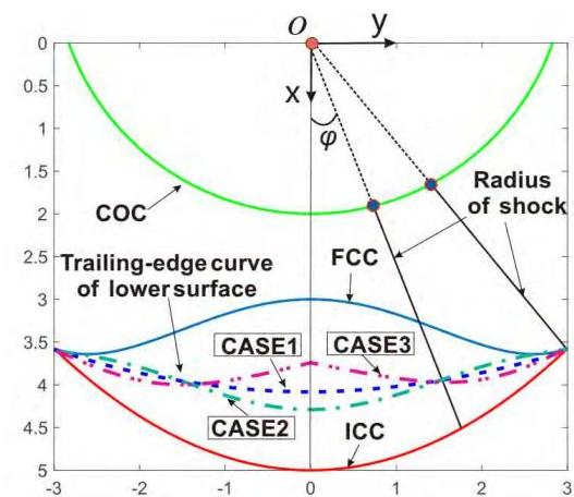
FIGURE 2. Design method of waverider with variable shock angle.

FIGURE 3. Sketch for the design of variable shock angle waverider.
The basic philosophy of the method is to relieve the partial geometric constraints of the conventional osculating cone waverider, and make the design parameters become more flexible. Because the method can greatly expand the design space of waverider, especially for the waverider with variable shock angle in this paper. Hence, all the waveriders are generated by the method. The design process of waverider with variable shock angle is illustrated as follows.
As shown in Fig.2, firstly, the coordinates of the trailing edge curve of the upper surface and the exit shock curve
are determined, here that is FCC and ICC, respectively. Then the COC is defined to ensure that each trailing curve point of the upper surface corresponds a sole point on the trailing curve of lower surface, for instance AiBi and AjBj in Fig.3. Herein, a new parameter is defined, named as expansion angle φ, based on the center of the coordinate (prescribed to be positive to the right and negative to the left). Once the three required curves are given, the basic conical flowfield and shock center for each expansion angle φi can be determined. It is evident that the line equation through the shock radius is x=y⋅cot(φi), then yield three intersection points, Oi′,Ai,Bi corresponding to φi in Fig.3, of which Oi′ indicates the center of the local exit shock, Ai and Bi indicating the point on the FCC and ICC, respectively. By now we can get the shock radius Oi′Bi, the local basic shock can be decided by shock angle βi,Oi′ represents the origin of the shock. The shock angle distribution βi can be designed according to requirement for special φi, then we can obtain different waveriders with variable shock angle. The leading edge point can be produced by inverse tracing Ai, the streamline tracing technology is utilized to generated the lower surface from the leading edge, then we can obtain the trailing edge of the lower surface C0−Ci−Cj. As a result, the configuration of waverider with variable shock angle is generated. In this paper, the FCC and ICC are given as x=3.0+0.1885y2−0.0138y4 and x=−0.1583y2+5, respectively.
For comparison, three waveriders with different shock angle distribution are attained using the new method. Fig. 4 displays the configurations of three designed waveriders, which share the same FCC, ICC and COC. Case 1 is the waverider with constant shock angle 12∘ at each osculation plane. Case 2 is generated by gradually decreasing from 14∘ in symmetry plane to 10∘ in the plane of endpoint linearly. Case 3 is designed by gradually increasing from 10∘ in symmetry plane to 14∘ in the plane of endpoint linearly. The average shock angle 12∘ is remained for each waverider. In Fig.2, the trailing edge curves of the three waveriders are illustrated and marked with special color and linestyle. The concrete property parameters are listed in Table.1.

FIGURE 4. Designed geometry configurations of different waveriders. (a) Case1. (b) Case2. © Case3.
TABLE 1. Geometric parameters of different waveriders.
| Cases | β(∘) | L(m) | b(m) | V(m3) | Smcf (m2) | Sp(m2) | Sb(m2) | η |
|---|---|---|---|---|---|---|---|---|
| case1 | 12 | 9.4093 | 6.0 | 9.0578 | 63.0208 | 30.9101 | 2.6917 | 0.1406 |
| case2 | 14−10 | 8.0215 | 6.0 | 9.5701 | 61.6321 | 30.0486 | 2.9146 | 0.1500 |
| case3 | 10−14 | 11.342 | 6.0 | 7.3931 | 66.0820 | 32.2266 | 2.2496 | 0.1178 |
From Table.1, we can conclude that the distribution of shock angle has a great effect on the volumetric efficiency.
The commercial software ANSYS Fluent [27] is selected as the simulation platform to numerically complete the simulation. Three-dimensional implicitly coupled Reynoldaveraged Navier-Stokes (RANS) equations are solved to obtain the results using the density-based solver. The second-order spatially Advection Upstream Splitting Method (AUSM) to the flux-vector is utilized, because it is less susceptible to Carbuncle phenomena and provides exact resolution of contact and shock discontinuities. The least-squares cell-based method is selected to compute the gradients. The SST k−ω turbulent model [28] is selected to gain the viscous results. The Courant-Friedrichs-Levy (CFL) number is set at 0.5 with proper under-relaxation factors to ensure stability. The boundary conditions imposed on the computational domain are given here. The surface of waverider is set as no slip and adiabatic wall boundary conditions. The pressure far-field boundary condition is selected in the inflow, while the pressure outlet boundary condition is set for outlet. The air is assumed to be a thermally and calorically perfect gas because air is compressible in hypersonic flow. The specific heat ratio γ is assumed to be a constant value as 1.4. The viscosity coefficient μ is calculated by Sutherland law in Eq.(6), the thermal conductivity k is determined by Prandtl number in Eq.(7).
μ=1.458×10⁻⁶T+110.4T1.5
TABLE 2. Grid convergence analysis.
| cases | Grid size | Cl | Cd | L/D |
|---|---|---|---|---|
| Coarse | 1,855,592 | 3.185e−02 | 4.425e−03 | 7.199 |
| Moderate | 3,352,222 | 3.187e−02 | 4.447e−03 | 7.166 |
| Refined | 5,322,252 | 3.188e−02 | 4.456e−03 | 7.154 |
k=PrμCp
In order to valid the credibility of the numerical approach in this paper, the numerical approach is verified using the provided waverider configuration by [29], which was an optimized cone-derived waverider using the MAXWARP (Maryland Axisymmetric Waverider Program) code. Moreover, the configuration was also been analyzed using CFL3D code, which can also be used to verify the results from Fluent. For the validation, the flight Mach number is 6 and flight altitude is 30 km , the Reynolds number based on the length of the waverider is 1.294×10⁸. The length of the waverider is 60 m . In order to investigate the effect of grid scale, the grid convergence is analyzed, the first layer grid height is set as 0.00001 m , the grid size of different scales are listed in the Table.2. The simulation of convergence analysis is performed by viscous condition. In the validation, the structured and hybrid grid are both adopted to complete and compare the results. A half ellipsoid domain is adopted to surround the waverider, the outlet extent passes through the base plane of waverider because the base drag is not numerically considered in this paper. The computational domain and generated grid are shown in Fig.5.
The grid refinement study shows little effect on the calculated results. Through the grid convergence analysis from Table.2, we can find that when the total grid numbers keeps

FIGURE 5. Computational domain and grid of waverider for verification at Ma=6 (a) computational domain; (b) structured grid; © hybrid grid.
TABLE 3. Comparison between different methods.
| methods | ParseError: KaTeX parse error: Expected 'EOF', got '_' at position 21: …rm{Cl}_{\text {_̲ }} invicid | ParseError: KaTeX parse error: Expected 'EOF', got '_' at position 21: …rm{Cl}_{\text {_̲ }} viscous | ParseError: KaTeX parse error: Expected 'EOF', got '_' at position 21: …rm{Cd}_{\text {_̲ }} invicid | ParseError: KaTeX parse error: Expected 'EOF', got '_' at position 21: …rm{Cd}_{\text {_̲ }} viscous | ParseError: KaTeX parse error: Expected 'EOF', got '_' at position 33: …hrm{D}_{\text {_̲ }} invicid | ParseError: KaTeX parse error: Expected 'EOF', got '_' at position 33: …hrm{D}_{\text {_̲ }} viscous |
|---|---|---|---|---|---|---|
| MAXWARP | 3.172E−2 | 3.168E−2 | 2.257E−3 | 4.089E−3 | 14.06 | 7.74 |
| CFL3D | 3.168E−2 | 3.228E−2 | 2.315E−3 | 4.391E−3 | 13.68 | 7.35 |
| Fluent_structured | 3.165E−2 | 3.185E−2 | 2.311E−3 | 4.439E−3 | 13.70 | 7.18 |
| Fluent_hybrid | 3.165E−2 | 3.171E−2 | 2.313E−3 | 4.196E−3 | 13.68 | 7.56 |

FIGURE 6. Pressure contour contrast between results in this paper and results from Ref. [29].
among 1.8 to 5.3 million, the difference caused by grid scale is very little. Therefore, although a refined grid can better capture shock and gain elaborate flowfield, to enhance the computational efficiency, a moderate grid is used for the numerical analysis in the study.
From Table.3, the results show that the numerical results of this paper can be well matched with the literature whatever structured or hybrid grid. For inviscid calculation, the error between Fluent and MAXWARP is only 2.56%, while for viscous calculation, the error between Fluent and CFL3D is 2.3%. The predicted results of Fluent show good agreement with MAXWARP and CFL3D, which verifies the feasibility and accuracy of the numerical approach in this paper. Fig. 6 shows the comparison of the outlet pressure contours obtained by the three methods. Hence, the numerical approach used in this paper is reliable.
The commercial software ICEM is employed to generate the grids. For the inviscid calculation, the unstructured grid is adopted in this paper, for the viscous analysis, the unstructured hybrid grid is used. The half model is adopted to save consumption time. The surface mesh size is approximately 1/200 of the length of the special waverider. The grid for inviscid simulation is between 1.5 million and 2 million in number. The distance away from the body to the first cell is 0.00001 m , ensuring that y+ based on the Reynolds number per unit is less than 5 . To solve the boundary layer flow in

FIGURE 7. Schematic diagram of grid of the waverider (unstructured grid for inviscid analysis and hybrid grid for viscous analysis).
detail, a 20 -layers boundary layer grid is generated near the wall with a total grid number about 2.5 million. The dynamic adaptive mesh technology is used in the calculation process to achieve better shock resolution. The computational domain is basically same as that in code validation and the generated grid is as shown in Fig. 7.
In this section, the aerodynamic performance has been analyzed by inviscid and viscous calculation. The design point is set at the freestream condition of Mach 6 at an altitude

FIGURE 8. Comparison of aerodynamic parameters of different designed waveriders. (a) Lift coefficient. (b) Drag coefficient. © Lift-to-drag ratio. (d) Relative position of the center of pressure.
of 30 km , the inflow pressure is 1200 Pa , and temperature is 226.5 K . The moment reference point is selected at the leading edge of the symmetry plane of the waverider. The projected area is selected as the reference area, and the length is selected as the reference length. The freestream flow is set as a pressure far-field boundary condition, and the outlet is set as a pressure outlet boundary condition. The wall is set as no slip and adiabatic wall boundary condition. The base pressure of waverider is considered in the analysis and the hypersonic base pressure model [30] of the base pressure coefficient, Cp, shown in Eq.(8), is used to obtained the base pressure.
Cp=−1/M2
TABLE 4. Increment percentage of aerodynamic performance of case 2 and case 3 relative to case 1 .
| case1 | case2 | case3 | |
|---|---|---|---|
| ΔL/D inviscid | N/A | −10.83% | 7.56% |
| ΔL/D viscous | N/A | −5.15% | −1.85% |
| Δη | N/A | 6.69% | −16.22% |
By comparison, it can be seen from Fig.8(a) and (b) that the lift coefficient and drag coefficient of case 2 are larger than case 1 and case3. Fig.8© reveals that the inviscid lift-to-drag ratio of case 2 is less than case 1 , the lift-to-drag ratio of case 3 is greater than case 1 at 0 degrees angle of attack. That is, case 3 owns the highest L/D, and case 2 is the
lowest whatever inviscid or viscous condition in an overall view. Through the analysis, we can know that the volumetric efficiency of case 3 and case 2 are the least and the largest, respectively, among the three configurations. It is obvious that there exists a contradiction between L/D and volumetric feature, the tradeoff should be considered in the design process. Consequently, it can be concluded that the distribution sequence of shock angle has a great influence on aerodynamic performance of the waveriders.
By analyzing the position of center of the pressure Fig.8(d), it can be obtained that the positions of the center change remarkably due to variable shock angle. Because the three waveriders are designed with variable shock angle on the different osculation planes. For case1, the shock angle is unchanged, pressure keeps basically the same at different osculation planes, which can be noticed in Fig.11(a). However, for case2, the high pressure is distributed near the central position and close to front position along the waverider, the low pressure distribute on both sides, and thereby the center of pressure move forwards relative to case1. Similarly, the surface pressure of case 3 shows inverted distribution, the high pressure locates on the both sides and close to the outlet of the waverider, therefore its center of pressure moves backwards. When the angle of attack is 0 degrees, the position of the center of case 2 and case 3 is 0.59 and 0.725 , respectively, while case 1 is 0.645 . As the angle of attack increases, the position of center of the pressure for case 1 and case 3 will move forward, however that of case 2 is basically unchanged. Compared to previous investigations [13], conventional waverider is generally generated by constant shock angle, its center of pressure usually locates at the 65% along the length of waverider and changes at a little range. From the calculated results, the lift coefficient of the viscous calculation is basically consistent with the inviscid result, but the drag coefficient has a significant increment because of viscosity. The angle of attack for the maximum L/D of inviscid and viscous analysis both appears at the angle of attack of 2 degrees. The maximum viscous L/D of case 3 is about 5.8 , while that of case 1 and case 2 is 5.4 and 5.05 , respectively. At the same time, it can also be seen that the viscosity has little effect on the position of the center of the pressure.
In order to investigate the pressure distribution regulation by variable shock angle, non-dimensional pressure P/P∞ of three sections in the spanwise direction are extracted, shown in Fig.9. Fig. 10 depicts the obtained inviscid pressure coefficient distribution of the lower surface under different cross-sections for different waveriders. The horizontal axis is rescaled by the local length at each station. As can be seen, for case 1 , the P/P∞ presents slight variation at different sections along the z-axis direction. However, we can find that for case 2 , the pressure at y=0 m is evidently the highest and that at y=2.5 m is the lowest among the three sections. And for case3, the pressure distribution exhibits adverse trend compared with case2. It is obvious that the pressure variation is basically identical to the distribution of the shock angle,

FIGURE 9. Chosen sections of the lower surfaces for different waveriders.

FIGURE 10. Dimensionless pressure distribution of different cross-sections.
TABLE 5. The freestream condition at different Mach.
| Ma | H/km | p∞/pa | T∞/K |
|---|---|---|---|
| 4 | 24.7 | 2669.04 | 221.254 |
| 6 | 30 | 1197.03 | 226.509 |
| 8 | 34 | 663.413 | 233.744 |
because larger shock angle leads to stronger shock intensity, the relative small shock angle produces weak shock. Overall, the pressure of case 2 gradually decreases from the symmetry plane to the two sides, and that of case 3 gradually increases from the symmetry to the sides. Consequently, we can design the shock angle to realize expected pressure distribution by the new method.
Additionally, Fig. 11 gives a comparison of the inviscid and viscous pressure contours for different longitudinal crosssections of the waveriders. According to the inviscid pressure distribution of case 1, case 2 and case3, the three waveriders analyzed can almost completely block the high-pressure region on the lower surface and satisfy good waverider characteristics. It can be seen from the viscous cross-section

©
FIGURE 11. Comparison of pressure contours at different slices. (a) Pressure contour slices of case1 (left:invisicd;right:viscous). (b) Pressure contour slices of case2 (left:invisicd;right:viscous). © Pressure contour slices of case3 (left:invisicd;right:viscous).
TABLE 6. Geometry parameters of blunted waveriders.
| Cases | L(m) | b(m) | V(m3) | Swct (m2) | Sp(m2) | Sb(m2) | η |
|---|---|---|---|---|---|---|---|
| case1 | 9.0959 | 5.721 | 9.0448 | 59.382 | 29.0143 | 2.6907 | 0.1496 |
| case2 | 7.8329 | 5.3768 | 9.5459 | 56.537 | 27.4837 | 2.9106 | 0.1637 |
| case3 | 10.1824 | 5.7886 | 7.3851 | 62.124 | 30.3015 | 2.2486 | 0.1252 |

FIGURE 12. Comparison of pressure contour of different waveriders between inviscid and viscous results. (a) Case1. (b) Case2. © Case3.
pressure contours in Fig. 11 that there exists obvious highpressure spillage on both sides of the waveriders. Because viscosity changes the shock intensity and induces a detached bow shock, the shock wave is no longer attached to the leading edge of the body.
In order to further analyze the flow field characteristics, the pressure contours at the outlet including the inviscid and viscous results, are given in Fig.12. It can be seen that under the condition of inviscid calculation, all the configurations can limit the high pressure to the lower surface, and the waverider characteristics are well maintained. The exit shock curves of case 1, case2, and case 3 are all in good agreement with the design curve. The high pressure zone of case 2 is mainly concentrated in the median region of the lower surface, while the high pressure region of case 3 is dispersed on both sides of the lower surface. And the outlet pressure distribution of case 1 is relatively uniform, which can be a promising design candidate for an engine integrated airframe.
From Table.4, it can be seen that compared with case1, the inviscid and viscous lift-to-drag ratio of case 2 reduces
TABLE 7. The increment change of design parameters of blunted waveriders relative to the original waveriders at zero incidence.
| case1 | case2 | case3 | |
|---|---|---|---|
| ΔV | −0.14% | −0.25% | −0.11% |
| Δη | 6.40% | 9.13% | 6.28% |
| ΔL/D | −7.88% | −8.16% | −7.80% |
by 10.83% and 5.15%, respectively, but the volumetric efficiency increases by 6.69%. The inviscid lift-to-drag ratio of case 3 increases by 7.56% with a little loss of 1.85% for viscous lift-to-drag ratio, however, the volumetric efficiency decreases by 16.22%. As a result, the inviscid lift-to-drag ratio of case 2 is lower than that of case 1 and case3. The reason could be explained that the inviscid lift-to-drag ratio is related to the volumetric efficiency, the increase of the volumetric efficiency leads to the decreased lift-to-drag ratio at the ondesign condition. Therefore, the distribution of the shock angle can make a significant impact on the aerodynamic performance of the waverider, which must be considered for optimization in the design process.
The aerodynamic performance of off-design condition for different waveriders is conducted on the key flight Mach numbers and angles of attack. Except for Ma 6, Ma 4 and Ma 8 are also selected to complete the investigation. In order to seek for distinction caused by Mach number, the inflow dynamic pressure, q=21ρv2=21pγMa2, is fixed as same as that of Mach 6. Here, q,ρ and v are the dynamic pressure, density and velocity of inflow, while p and Ma are the static pressure and Mach number of inflow, respectively. Because the Mach number is varied in this study, the static pressure magnitude shows difference. For practical flight, the flight altitude would be different according to the definition of dynamic pressure. Table. 5 lists the specific flight conditions for each Mach number case analyzed.
In Fig.13, the aerodynamic performance of different waveriders under off-design conditions is presented. The effect by different Mach number yields no deviations from expected results. As shown in Fig.13(a) and (b), the inviscid results show that as the Mach number increases, the lift coefficient and drag coefficient decrease. The lift-to-drag ratio monotomically increases with increased Mach number, shown in Fig.13©. It can be seen from Fig.13(d) that the increase of Mach number causes the center of pressure to move slightly backward, that is, the increase of the flight Mach number helps to improve the stability of the waverider. The viscous calculated results of the lift coefficient for different waveriders are the same as the inviscid. The drag coefficient decreases with the increase of Mach number. Compared with inviscid result, the viscous drag coefficient increases greatly because of the existence of viscosity. For example, for case 1, the inviscid lift-to-drag ratio of Mach number 4 is 5.26 , the viscous L/D is 3.93 , the viscosity makes a loss by 25.3%. When the Mach number is 8 , the inviscid

FIGURE 13. Comparison of aerodynamic parameters of different designed waveriders at different Mach. (a) Lift coefficient. (b) Drag coefficient. © Lift-to-drag ratio. (d) Relative position of the center of pressure.

FIGURE 14. Perspective view of dimensionless pressure contour at different slices of case 2 under blunted condition.

FIGURE 15. Dimensionless pressure contours of fringe surface of case2.
lift-to-drag ratio is 7.58 , the viscous lift-to-drag ratio is 5.03 , the lift-to-drag ratio decreases by 33.64% due to viscosity. However, the inviscid and viscous lift-to-drag ratio increases by 44.1% and 28.0%, respectively, when the Mach number increases from 4 to 8 . In addition, from Fig.13(d), with the

FIGURE 16. Aerodynamic performance of blunted waveriders and increments relative to original configurations. (a) Lift coefficient. (b) Drag coefficient. © Lift-to-drag ratio. (d) Relative position of the center of pressure.
increase of Mach number, the position of the center of the pressure does not change significantly. Accordingly, it can be concluded that the viscosity has little influence on the position of the center of pressure.
Restricted by aerodynamic heating and manufacture techniques, the realistic waverider can not be processed with sharp leading edge [31], [32]. Bluntness makes ideal waveriders shapes changed and leads to the perturbation of flowfield. The leading radius is enlarged after bluntness, which can significantly relieve the severe aero-heating problem. Therefore, bluntness is very important and only blunted waverider could be applied to engineering for practical hypersonic configurations. Accordingly, the blunted waveriders should also be
analyzed to predict aerodynamic perfomance close to practical engineering application. Herein, the viscous analysis is executed with the bluntness radius of 10 mm in the leading edge. The ICEM CFD commercial software is employed to generate the structured grid, the first layer grid height is set to 0.00001 m and the total grid number by half computed domain is about 2.0 million. The aerodynamic reference length and area of the blunted waveriders keep consistent with original configurations.
To obtain the flow characteristics, the non-dimensional pressure distribution P/P∞ of case 2 at different slices is illustrated in Fig.14, where these slices are normal to the inflow direction along the waverider. It is obvious that bluntness leads to more high pressure leakage on both sides. The leading edge shock has detached from the leading edge and a
more noticeable bow shock is developed in the leading edge. In addition, Fig. 15 gives the surface pressure distribution of the fringe of the blunted waverider case 2 , it is interesting that the maximum P/P∞ is not located in the symmetry but away from symmetry plane and the maximum P/P∞ reaches 42 . Therefore, it can be concluded that the distribution of shock angle can change the high pressure distribution on the fringe, which is tightly linked with thermal protection.
Fig. 16 shows the aerodynamic force variations and increments relative to original configurations. We can see from Fig.16(a) and (b) that the lift coefficient and drag coefficient of different waveriders increase with the increasing the angle of attack. It can also be observed that bluntness makes the lift coefficient decrease and the increment percentage appears clear difference. However, bluntness leads to the increase of drag coefficient when the angle of attack is below at 2∘, the negative increment can be noted once the angle of attack is larger than 2∘. The increment percentage decreases with the increase of angle of attack. For case2, the drag coefficient of original and blunted configuration is 0.00773 and 0.00823 at zero incidence, respectively. After bluntness, the drag coefficient increases by 6.5%. Additionally, as shown in Fig.16©, bluntness also leads to the loss of L/D, for instance, the L/D of case 2 reduces by 8.2% primarily due to the detached shock wave. However, the trend slows down with increasing angle of attack, which can be obtained from Fig.16©. Besides, the center of pressure shifts slightly for case 1 and case 2 under blunted condition so the change can be neglected. But the change of case 3 is close to 4% and should be considered in the engineering application. From above results, the difference by the distribution of shock angle can lead to different intrinsic properties of waveriders. Therefore, the waveriders with variable shock angle should be treated differently.
In this paper, a novel waverider with variable shock angle based on osculating cones theory is proposed. Three different waveriders are designed and discussed. According to the study, we can obtain the following conclusions:
while the negative increment of L/D for case 2 is greater than case 1 and case3.
CFD Computational Fluid Dynamics
HCW High-pressure Capturing Wing
FCC Flow Capture Curve
ICC Inlet Capture Curve
COC Curve of Center for the exit shock
Xcp the position of center of pressure
Cl lift coefficient
Cd drag coefficient
L/D lift-to-drag ratio
y+ dimensionless distance from the wall
L length of vehicle, m
b width of vehicle, m
μ viscosity coefficient, kg/(m⋅s)
η volumetric efficiency
k thermal conductivity, W/(m⋅K)
Pr Prandtl number
β shock angle, ∘
η volumetric efficiency
Sp projected area of vehicle, m2
Swet wetted area of vehicle, m2
Sb base area, m2
γ specific heat ratio
α angle of attack, ∘
[1] F. Wang, H. Ding, and M. Lei, “Aerodynamic characteristics research on wide-speed range waverider configuration,” Sci. China E, Technol. Sci., vol. 52, no. 10, pp. 2903-2910, 2009.
[2] W. Wang, Z. Hou, S. Shan, and L. Chen, “Optimal periodic control of hypersonic cruise vehicle: Trajectory features,” IEEE Access, vol. 7, pp. 3406-3421, 2019.
[3] V. Borsch, “Flow on the wind side of wedge-derived waveriders revisited, or do on-design strong planar shock waves really exist?” in Proc. 44th AIAA Aerosp. Sci. Meeting Exhib., 2006, p. 122.
[4] N. Takashima and M. J. Lewis, “Optimization of waverider-based hypersonic cruise vehicles with off-design considerations,” J. Aircraft, vol. 36, no. 1, pp. 235-245, 1999.
[5] K. Kontogiannis, A. Söbester, and N. Taylor, “Efficient parameterization of waverider geometries,” J. Aircraft, vol. 54, no. 3, pp. 890-901, 2016.
[6] T. R. F. Nonweiler, “Aerodynamic problems of manned space vehicles,” Aeronaut. J., vol. 63, no. 585, pp. 521-528, 1959.
[7] M. P. F. Rasmussen, “Waverider configurations derived from inclined circular and elliptic cones,” J. Spacecraft Rockets, vol. 17, no. 6, pp. 537-545, 1980.
[8] M. Rasmussen, M. Jischke, and D. Daniel, “Experimental forces and moments on Cone-derived waveriders for m∞=3 to 5,” J. Spacecraft Rockets, vol. 19, no. 6, pp. 592-598, 1982.
[9] H. Sobieczky, F. Dougherty, and K. Jones, “Hypersonic waverider design from given shock waves,” in Proc. 1st Int. Hypersonic Waverider Symp. College Park, MD, USA: Univ. Maryland College Park, 1990, pp. 17-19.
[10] X. He, J. Le, and S. Qin, “Design and analysis osculating general curved cone waverider,” Aircraft Eng. Aerosp. Technol., vol. 89, no. 6, pp. 797-803, 2017.
[11] F. Ding, J. Liu, C.-B. Shen, and W. Huang, “Novel approach for design of a waverider vehicle generated from axisymmetric supersonic flows past a pointed von karman ogive,” Aerosp. Sci. Technol., vol. 42, pp. 297-308, Apr. 2015.
[12] F. Ding, C.-B. Shen, J. Liu, and W. Huang, “Comparison between novel waverider generated from flow past a pointed von karman ogive and conventional cone-derived waverider,” Proc. Inst. Mech. Eng., G, J. Aerosp. Eng., vol. 229, no. 14, pp. 2620-2633, 2015.
[13] Z. Liu, J. Liu, F. Ding, and Z. Xia, “Novel methodology for wide-ranged multistage morphing waverider based on conical theory,” Acta Astronaut., vol. 140, pp. 362-369, Nov. 2017.
[14] K. Cui, G.-L. Li, Y. Xiao, and Y.-Z. Xu, “High-pressure capturing wing configurations,” AIAA J., vol. 55, no. 6, pp. 1909-1919, 2017.
[15] P. Rodi, “Vortex lift waverider configurations,” in Proc. 50th AIAA Aerosp. Sci. Meeting Including New Horizons Forum Aerosp. Exposit., 2012, p. 1238.
[16] J. Liu, F. Ding, W. Huang, and L. Jin, “Novel approach for designing a hypersonic gliding-cruising dual waverider vehicle,” Acta Astronaut., vol. 102, pp. 81-88, Sep. 2014.
[17] S. B. Li, W. Huang, Z. G. Wang, and J. Lei, “Design and aerodynamic investigation of a parallel vehicle on a wide-speed range,” Sci. China Inf. Sci., vol. 57, no. 12, pp. 1-10, 2014.
[18] S. B. Li, Z. G. Wang, W. Huang, J. Lei, and S. R. Xu, “Design and investigation on variable mach number waverider for a wide-speed range,” Aerosp. Sci. Technol., vol. 76, pp. 291-302, May 2018.
[19] Z.-T. Zhao, W. Huang, S.-B. Li, T.-T. Zhang, and L. Yan, “Variable Mach number design approach for a parallel waverider with a wide-speed range based on the osculating cone theory,” Acta Astronaut., vol. 147, pp. 163-174, Jun. 2018.
[20] J. Wang, C. Liu, P. Bai, J. Cai, and Y. Tian, “Design methodology of the waverider with a controllable planar shape,” Acta Astronaut., vol. 151, pp. 504-510, Oct. 2018.
[21] L. L. Chen, X. L. Deng, Z. Guo, Z. X. Hou, and W. K. Wang, “A novel approach for design and analysis of volume-improved osculating-cone waveriders,” Acta Astronaut., to be published. doi: 10.1016/j.actaastro.2019.02.033.
[22] B. Mangin, R. Benay, B. Chanet, and A. Chpoun, “Optimization of viscous waveriders derived from axisymmetric power-law blunt body flows,” J. Spacecraft Rockets, vol. 43, no. 5, pp. 990-998, 2006.
[23] Y. Wang, S. Yang, D. Zhang, and X. Deng, “Design of waverider configuration with high lift-drag ratio,” J. Aircr., vol. 44, no. 1, pp. 144-148, 2007.
[24] X. He and M. L. Rasmussen, “Computational analysis of off-design waveriders,” J. Aircr., vol. 31, no. 2, pp. 345-353, 1994.
[25] G. O. Stecklein, “A comparative study of numerical versus analytical waverider solutions,” M.S. thesis, Air Force Inst. Technol. Air Univ., Wright-Patterson AFB, OH, USA, Dec. 1991.
[26] G. I. Taylor and J. W. Maccoll, “The air pressure on a cone moving at high speeds-II,” Proc. Roy. Soc. London A, Math., Phys. Eng. Sci., vol. 139, no. 838, pp. 278-297, 1933.
[27] ANSYS Fluent Theory Guide, ANSYS, Canonsburg, PA, USA, 2015.
[28] F. Ding, J. Liu, C.-B. Shen, and W. Huang, “Novel inlet-airframe integration methodology for hypersonic waverider vehicles,” Acta Astronaut., vol. 111, pp. 178-197, Jun. 2015.
[29] N. Takashima and M. J. Lewis, “Navier-Stokes computation of a viscous optimized waverider,” J. Spacecraft Rockets, vol. 31, no. 3, pp. 383-391, 1994.
[30] P. E. Rodi, “On using upper surface shaping to improve waverider performance,” in Proc. AIAA SciTech Forum AIAA Aerosp. Sci. Meeting, 2018, p. 554.
[31] X.-Q. Chen, Z.-X. Hou, J.-X. Liu, and X.-Z. Gao, “Bluntness impact on performance of waverider,” Comput. Fluids, vol. 48, pp. 30-43, Sep. 2011.
[32] W. Santos, “Bluntness effects on lift-to-drag ratio of leading edges for hypersonic waverider configurations,” in Proc. 18th AIAA/3AF Int. Space Planes Hypersonic Syst. Technol. Conf., 2012, p. 5802.

LILI CHEN received the B.S. degree in aircraft system and engineering and the M.S. degree in aeronautical and astronautical science and technology from the National University of Defense Technology (NUDT), China, in 2013 and 2015, respectively, where he is currently pursuing the Ph.D. degree in aeronautical and astronautical science and technology with the College of Aerospace Science and Engineering under the supervision of Prof. Z. Guo. He has authored or coauthored several articles in the field of aerodynamic configuration design and CFD. His current research interests include aerodynamic design for hypersonic cruise vehicles.

ZHENG GUO received the Ph.D. degree in computational fluid dynamics from the National University of Defense Technology (NUDT), in 2002. He was a Visiting Academic with the University of Cambridge, in 2009. He is currently a Professor and the Head of the UAV Technology Research Group, College of Aerospace Science and Engineering, National University of Defense Technology. His current research interests include the conceptual design and aerodynamic configuration design of near-space vehicles and UAVs, computational aerodynamics, fluid and structure interaction, and hypersonic vehicle design. He has published more than 70 academic papers and three text books. He holds 30 authorized patents.
XIAOLONG DENG received the Ph.D. degree in engineering physics from Ghent University, Belgium, in 2015. He is currently a Lecturer with the National University of Defense Technology of China. His current research interests include the conceptual design and dynamics of near-space vehicles.

ZHONGXI HOU received the Ph.D. degree in computational fluid dynamics from the National University of Defense Technology (NUDT), China, in 2000, where he is currently a Professor in aeronautical and astronautical science and technology and also an Associate Dean of the College of Aerospace Science and Engineering. He has authored a monograph and over 40 international journals. His current research interests include the aircraft conceptual design of high-altitude longendurance (HALE) solar-powered unmanned aircraft systems (UAS) and hypersonic vehicle design.

WENKAI WANG received the B.S. degree in space engineering and the M.S. degree in aeronautical and astronautical science and technology from the National University of Defense Technology (NUDT), China, in 2012 and 2014, respectively, where he is currently pursuing the Ph.D. degree in aeronautical and astronautical science and technology under the supervision of Prof. Z. Hou. He has authored or coauthored several articles in the field of aircraft design and control. His current research interests include preliminary design, flight dynamics, and optimal control for hypersonic cruise vehicles.
A generic aerospace vehicle including an airframe, inlet, and tail-wings, is developed by means of the waverider concept in this paper. The stream surfaces of the hypersonic flow past a cone with both transverse and longitudinal curvatures are used to design the forebody configuration. By suitably choosing the even polynomial stream surfaces, the airframe, horizontal stabilizers, and inlet can be constructed together. In addition, several small caret-waveriders are patched on this configuration as the vertical fins for the furnishment of a hypersonic vehicle. Also calculated are the mass flow rate, lift, drag, and lift-to-drag ratio. Moreover, effects of the various parameters on the shape and aerodynamic performance of this high-speed vehicle are found and discussed in detail. Hence, an overall aerodynamic design of a hypersonic vehicle is established in a simple and systematic way. Nomenclature a = speed of sound G mn-shock-perturbation factor t = length of right circular cone i w-length of waverider q = dynamic pressure, p R = distance quantities, rO/18 r,0,(j> = spherical coordinate system s = specific entropy U, V, W = spherical velocity components perturbation associated with curvature u,v,w-velocity components in spherical coordinates X, Y = nondimensional cartesian coordinate system, x/lB, y/18 x,y,z = Cartesian coordinate system p = semivertex angle of the unperturbed shock 8 = semivertex angle of the unperturbed cone body € = perturbation parameter (defined as extremely small) a = ratio of shock angle to cone semivertex angle, ft/8 Subscripts c = compression surface quantities F = forebody quantities / = freestream surface quantities fin = tailfin quantities i = inlet surface quantities L = inlet left side quantities t = shock wave in base plane m = mth term in expansion n = nth term in expansion o = zero-order, unperturbed flow quantities R = inlet right side quantities s = shock wave w = waverider surface quantities oo = freestream condition Superscripts * = quantities proposed in Ref. 8
31st Aerospace Sciences Meeting, 1993
Waveriders have been constructed from hypersonic flowfields behind arbitrary three dimensional shock shapes using a special spatial marching finite difference approach. This routine exploits the simplicity and efficiency of spatial marching techniques and the accuracy of the method of characteristics, and greatly simplifies the waverider design process. The stream surfaces behind the shock shapes form the compression surface for a new family of waveriders, providing greatly needed flexibility in the design and optimization of such vehicles. Emphasis is placed on the influence of the shock shape and its relationship to the aerodynamic characteristics of the resulting waverider. A systematic approach based on the direct search Rosenbrock optimization technique is developed in an effort to carve waveriders with optimal aerodynamic quantities for given dimension and free stream conditions. Waveriders carved from arbitrary oblique and axisymmetric shock waves are evaluated and validated against those constructed using conventional numerical techniques. Finally, a new class of waveriders carved from arbitrary three dimensional shock shapes are presented and discussed, J. Int roduct ion A basic feature of hypersonic vehicles with reasonable dimensions and meaningful volume is the creation of relatively strong shock waves emanating from their foremost surfaces in flight. Associated with the shock waves are severe aerothermodynamic and aeroelastic design problems. This feature is characteristic 01 both ballistic and lifting vehicles, so in either case the relationship between shock wave shape and vehicle shape is of fundamental importance to effective vehicle design. The goal is to design a hypersonic vehicle by effectively Graduate Hypersonic Fellow
53rd AIAA Aerospace Sciences Meeting, 2015
Methodologies required for the creation of hypersonic aircraft configurations based on the waverider concept were developed and validated. The design space for these configurations was formulated by using an algorithm that coupled the directional derivatives to the conservation laws and used to generate flow fields in the form of organized sets of stream-surfaces. In general, the design space generated waverider configurations with sharp leading edges. Consequently, a carving methodology was developed and implemented to transform the idealized waverider geometries into practical aircraft configurations with blunted leading edges. Further, methodologies, based on both empirical and analytical relations, were developed and applied with the goal of evaluating the aerothermo-dynamic performance of the resulting hypersonic aircraft configurations. In this effort, methodologies to determine the local pressure, skin-friction and heat flux were also developed, implemented and validated. For example, in regions where the surfaces of vehicle configuration allow for the use of planar models, the flat plate viscous relations for compressible flow were used. However, in other regions, such as, the blunted leading edges, flat plate viscous relations are not applicable, and in those regions the modified Newtonian theory, Fay-Riddell theory and Modified Reynolds analogy were applied. At every stage of this newly develop methodology, the design and analysis routines were validated by either using existing analytical solutions, empirical relationships or independent computer simulation. For example, the set of streamlines that represents the inversely created hypersonic flow field were compared to Taylor-Maccoll exact solution. Similarly, the observed relationships between the local Stanton number and the skin friction coefficient with the local Reynolds number along the 'slow varying' regions of the vehicle surface compared extremely well to that of experimental findings. Of particular importance to this effort is the creation of an automated grid generation routine. For the purposes of independent CFD simulations, structured mesh, orthogonal to both the vehicle surface and the freestream, can be generated around the resulting hypersonic vehicle configuration. Based on users' requirements the grid information is exported to appropriate CFD codes in their respective format. The efficacy of the grid generation technique and the capability of the hypersonic vehicle tool were analyzed. Overall, the independent simulations compared well with the data predicted by the tool. In external flow field comparisons, both approaches; the independent CFD simulations and the vehicle design tool, recovered the exact solution described by the Taylor-Maccoll solution. In addition, the pressure distribution on the vehicle surface compares extremely well to CFD predictions. However, the distribution of the viscous-related surface properties left a bit more to be desired.
& Proceedings ???????? ???????????????| ???????????????| ?????? …, 1999
An analytical, power-law derived hypersonic waverider model is developed using a three-dimensional wedge-based flowfield with viscous effects. The model is designed for simple parametric tradeoffs, and understanding of more complex optimization results. This analytical model is validated against a viscous optimized conical waverider created using an inverse design technique. Off-design performance of the analytical model at varying Mach numbers and angles-of-attack is validated using an optimized shock defined waverider (which itself has been validated with an Euler CFD calculation). Both the variable wedge angle waverider and shock defined waverider calculations had the same magnitude of error in comparison to the CFD validation L/D's (maximum of 2% difference). The variable wedge angle method calculated the same aerodynamic and geometric properties of higher order methods in orders of magnitude less time.
The performance of 23 kinds of waveriders, derived from different conical flowfields, is analyzed by the numerical computation under the conditions of fight speed of Mach 6, attack angle of 0° and flight altitude of 30 km. These results indicate that the performance is influenced by the shapes and the width to height ratios (W/H ) of generating cones. The geometrical parameter and the lift coefficient are proportional to W/H, while the drag coefficient and the lift to drag ratio (L/D ) have extreme values. Considering the base drag and the computation errors, the waverider with the highest L/D is cut from the elliptical cone's flowfield (W/H = 1.5-1.618), and the configuration with the lowest drag can also be obtained at W/H = 1:1.5. Accordingly, good suggestions are proposed for practical design based on these computational results. hypersonic vehicle, waverider, computational fluid dynamics
1993
The paper describes the first assessment study of a waverider-derived Mach 5 aircraft design using fuselage integrated-underslung over/under turboramjets with endothermic fuel. The study is based on a tanker-to-tanker mission, which begins at Mach 0.8 and 30,000 feet, with the vehicle accelerating to Mach 12 at constant altitude and then to Mach 5 while climbing to about 90,000 feet. The paper describes the vehicle, the aerodynamic analysis, and the propulsion system and its installed performance, structure design, and analysis. The mission simulation was run using the CSOTAV code developed by the NASA Langley Research Center.
Journal of Spacecraft and Rockets, 2006
A method based on a Euler code is used to study waveriders generated from the flowfield around cones or axisymmetric power-law blunt bodies. In the cone case, the results are compared with those given by the Taylor-Maccoll system and inviscid hypersonic small-disturbance theory. This last theory shows its limits at a Mach number of 5, for cone angles providing the best lift-to-drag ratios. In the axisymmetric power-law blunt body flows case, the optimization is led using a nonlinear simplex method to get the upper surface that enables the waverider to have the best lift-to-drag ratio, the thickness-to-length ratio being fixed. Compared with the cone-derived waverider, the proposed blunt-body-derived model allows a 20% gain in volume for near equal optimized lift-to-drag ratios.
Aerospace Science and Technology, 2020
This is a PDF file of an article that has undergone enhancements after acceptance, such as the addition of a cover page and metadata, and formatting for readability, but it is not yet the definitive version of record. This version will undergo additional copyediting, typesetting and review before it is published in its final form, but we are providing this version to give early visibility of the article. Please note that, during the production process, errors may be discovered which could affect the content, and all legal disclaimers that apply to the journal pertain.
5th International Aerospace Planes and Hypersonics Technologies Conference, 1993
The results of a feasibility study of a hypersonic waverider research vehicle with a hydrocarbon scramjet engine are presented. The scramjet engine concept consists of a preburner into which a small amount of fuel is burned with onboard liquid oxygen and injected into the airflow, upstream of the main fuel injector locations, thus ensuring that main fuel combustion is present and uninterrupted. The integrated waverider/scramjet geometry is optimized with a vehicle synthesis code to produce a maximum product of the lift-to-drag ratio and the cycle specific impulse, hence cruise range. Computational fluid dynamics is employed to provide engine performance and a nose-to-tail analysis of the vehicle at the on-design conditions. Comparisons are made between the results of the two analysis techniques and some differences are noted.
According to its Charter, the mission of AGARD is to bring together the leading personalities of the NATO nations in the fields of science and technology relating to aerospace for the following purposes: