 Evert Lataire
580 California St., Suite 400
San Francisco, CA, 94104
Academia.edu no longer supports Internet Explorer.
To browse Academia.edu and the wider internet faster and more securely, please take a few seconds to upgrade your browser.
2011
This paper utilizes CFD (Computational Fluid Dynamics) methods to investigate the bank effects on a tanker moving straight ahead at low speed in a canal characterized by surface piercing banks. For varying water depths and ship-tobank distances, the sinkage and trim as well as the viscous hydrodynamic forces on the hull are predicted mainly by a steady state RANS (Reynolds Averaged Navier-Stokes) solver, in which the double model approximation is adopted to simulate the flat free surface. A potential flow method is also applied to evaluate the effect of the free surface and viscosity on the solutions. In addition, focus is placed on V&V (Verification and Validation) based on a grid convergence study and comparison with EFD (Experimental Fluid Dynamics) data, as well as the exploration of the modelling error in RANS computations to enable more accurate and reliable predictions of the bank effects. NOMENCLATURE α Constant (-) δ RE Discretization error (-) ν Kinematic viscosity (N•s•m -2 ) ρ Density of water (kg•m -3 ) σ Sinkage (m) ij Average stress (N•m -2 ) τ Trim (°) 1.
2014
Although CFD computation can predict resistance for conventional vessels with reliable accuracy at deep water condition, its predictive capability at shallow water condition is still unclear. One of the main objective of this study is to assess the accuracy of CFD computation for this kind of configuration and attempt to identify physical phenomena poorly modeled in the simulation. Shallow water resistance and squat are predicted for two different ship models, namely the DTC container ship, and the KVLCC2 tanker. Numerical uncertainty related to grid density, turbulence model as well as near wall turbulence model treatment will be investigated. Computation at full scale is also performed for the container ship to check the scale effect in ship squat prediction.
2016
This paper presents a comparison of numerical methods with model test results for squat (sinkage and trim) of a 1:75 KVLCC2 model in the Flanders Hydraulics Research towing tank, at a range of rectangular canal widths and depths. The numerical methods are the Linear-2D and Nonlinear-1D methods in ShallowFlow, the Double-Body method in HullWave and the Rankine-Source method in GL Rankine. Analysis of the model tests showed that in the narrowest canals, mass flux past the ship was not conserved, nevertheless it appears that the Nonlinear-1D method may give good results for the narrowest canals. The Linear-2D method was found to give good results in the widest canal, particularly at the shallowest water depth. The Rankine-Source method was found to give good results for the widest canal, particularly at high speed. The Double-Body method was found to give quite consistently good results across all conditions.
Port-Said Engineering Research Journal
Minor grounding or contact accidents may occur from time to time in Suez Canal. However, in March 2021, the economic ramifications of a critical grounding resounded around the world and were still felt after the Ever-Given container ship was freed from the banks. The results of a computational investigation of a ship cruising through Suez Canal are presented in this study, and hopefully can be utilized to foresee and prevent future ship's squat and bank effects throughout the determination of proper trim. The KRISO Container Ship (KCS) was picked as the example vessel for this investigation, carried out through the commercial code STAR-CCM+, and representing a comprehensive CFD analysis of such an event. The governing equations are expressed in integral form by the finite-volume based solver STAR-CCM+. The CFD investigation is performed by utilizing a Reynolds-Averaged Navier-Stokes (RANS) solver, a k-ε turbulence model and the Volume of Fluid (VOF) approach. The CFD model is validated based on the ships' experimental data. The investigation empowers shipmasters and marine pilots to comprehend the effects of squat thus avoiding ship accidents when going through Suez Canal.
Ships and Offshore Structures, 2019
In recent years, there has been an increased use of large displacement vessels for cargo transport around the world. Due to space constraints in the matured ports, the clearance available between the approach channels and berths could not be increased or modified. Hence, the vessels passing in close vicinity to the berthed vessels has become a routine. It is essential to study the passing vessel and berthed vessel interaction for ensuring safety so that the mooring systems could be designed for the increased forces. In this paper, a study envisaging such interaction using Computational Fluid Dynamics (CFD) simulations has been attempted to determine the passing vessel effect on a moored tanker. The CFD solution used is based on a three-dimensional, unsteady, inviscid flow. Initially, the CFD simulation has been carried out for existing experimental data from published paper for validation and has been extended to a range of parameters such as passing vessel displacement, velocity, separation distance and water depth. The effect of each parameter on passing vessel forces is explained in detail. It is observed from the results that the longitudinal and transverse forces on the moored vessel become negligible for separation distance more than three times the width of the vessel. Also, the study provides a proper insight into the effect of full hull forms of various displacements on the passing vessel forces.
Jurnal Teknologi, 2014
Liquefied Natural Gas (LNG) tanker often travels through shallow waters with visible banks to load and unload its hazardous cargo. Manoeuvring of vessel in shallow water is relatively difficult and always exposed to higher risk of grounding and collision compared to deep water due to effect of ship-bank interaction. This research work examines ship-bank interaction effects of a LNG tanker in shallow water. CFD analysis is performed to investigate the hull hydrodynamic forces/moments and ship-bank interaction forces/moments which are further validate by captive model tests.
Journal of Marine Science and Engineering
The scope of the present study is to investigate the effects of various geometrical hull features, such as tunnels, spray rails and whiskers on the hydrodynamic performance of a high-speed planing hull. The criteria being tested to emphasize the boat performance are the total drag, sinkage and trim angle. In addition, the decomposition of the resistance into viscous and wave-making resistance are taken into consideration. The study starts with a validation test against experimental data in order to accentuate the capability of the Computational Fluid Dynamics CFD simulation to accurately predict the total drag and trim angle of the initial form. This is later followed by a verification study based on the Richardson Extrapolation method with a grid- and time-step-convergence test in order to predict the numerical errors during the simulation. After establishing the simulation parameters regarding the proper grid size and time step, the comparative study takes place for five hull shap...
Ocean Engineering, 2020
A physical model test was performed, to which a scaled model (1:40) was designed and constructed to carry two Laser Doppler Velocimetry sensors and provide optical access at different locations along the hull to detect the stream close to bottom of the hull and resolving the boundary layer flow at the hull. The measurement campaign was conducted in a shallow water towing tank and included a range of water depths and ship speeds such that the influence of each became analysable. The purpose of the experiment is to provide validation data to further corroborate a numerical approach and to gain deeper insight in the flow conditions in the gap flow underneath the vessel in very shallow water. In addition the extension of the effect of propulsion on the dynamic sinkage and trim in very shallow water was checked. Even though for one particular ship design and restricted to model scale 1:40, the results are regarded a valuable basis for further investigations on this phenomenon.
Computational Simulations and Applications, 2011
Journal of Hydrodynamics, 2010
This paper presents a study on the Verification and Validation (V&V) of CFD solutions for a tanker without appendages manoeuvring at varying drift angles and water depths. A steady state Reynolds-Averaged Navier-Stokes solver is applied to solve the viscous flow around the ship neglecting the free surface, sinkage and trim. Discretization errors and uncertainties in hydrodynamic forces and moments are estimated through grid convergence studies. Validation is performed by comparison with model test data.
The demand for high-speed boats that operating near to shoreline is increasing nowadays. Understanding the behavior and attitude of high-speed boats when moving in different waterways are very important for boat designer. Usually, they using experimental model testing for resistance prediction and dynamic force but this method is high consuming time, and cost. When planing boats are moving at high speed, two forces participate in their support, they are the hydrodynamic lift created by the shape of the planing hull, and the lift force resulting from displacing part of the liquid (buoyancy force). This research uses a CFD (Computational Fluid Dynamics) analysis to investigate the shallow water effects on prismatic planing hull. The turbulence flow around the hull was described by Reynolds Navier Stokes equations RANSE using the k-ɛ turbulence model. The free surface was modelled by the volume of fluid (VOF) method. The analysis is steady for all the ranges of speeds except those close to the critical speed range Fh =0.84 to 1.27 due to the propagation of the planing hull solitary waves at this range. For this fluctuation in the results, the average numerical value of the results was taken to compare it with the experiment. In this study, the planing hull lift force, total resistance, and wave pattern for the range of subcritical speeds, critical speeds, and supercritical speeds have been calculated using CFD. The numerical results have been compared with experimental results. The dynamic pressure distribution on the planing hull and its wave pattern at critical speed in shallow water were compared with those in deep water. The numerical results give a good agreement with the experimental results whereas total average error equals 7% for numerical lift force, and 8% for numerical total resistance. The worst effect on the planing hull in shallow channels occurs at the critical speed range, where solitary wave formulates.
L Zou, Chalmers University of Technology, Sweden
L Larsson, Chalmers University of Technology, Sweden
G Delefortrie, Flanders Hydraulics Research, Belgium
E Lataire, Maritime Technology Division Ghent University, Belgium
This paper utilizes CFD (Computational Fluid Dynamics) methods to investigate the bank effects on a tanker moving straight ahead at low speed in a canal characterized by surface piercing banks. For varying water depths and ship-tobank distances, the sinkage and trim as well as the viscous hydrodynamic forces on the hull are predicted mainly by a steady state RANS (Reynolds Averaged Navier-Stokes) solver, in which the double model approximation is adopted to simulate the flat free surface. A potential flow method is also applied to evaluate the effect of the free surface and viscosity on the solutions. In addition, focus is placed on V&V (Verification and Validation) based on a grid convergence study and comparison with EFD (Experimental Fluid Dynamics) data, as well as the exploration of the modelling error in RANS computations to enable more accurate and reliable predictions of the bank effects.
| a | Constant (-) |
|---|---|
| δRE | Discretization error (−) |
| v | Kinematic viscosity (N⋅s⋅m−2) |
| ρ | Density of water (kg⋅m−3) |
| σ | Sinkage (m) |
| σˉij | Average stress (N⋅m−2) |
| τ | Trim (∘) |
| ϕ0 | Extrapolated solution at zero grid size (-) |
| ϕi | i th grid solution (-) |
| ω | Specific dissipation rate (s−1) |
| Aw | Water plane area (m2) |
| B | Beam (m) |
| CF | Frictional resistance coefficient (-) |
| CPV | Viscous pressure resistance coefficient (-) |
| D | Experimental data (-) |
| E | Comparison error (-) |
| Fi | Body force (N⋅kg−1) |
| Fr | Froude number, Fr=Ui′gLPP(−) |
| g | Acceleration of gravity (m⋅s−2) |
| h | Water depth (m) |
| h1 | Finest grid step (-) |
| hi | i th grid step (-) |
| Iw | Longitudinal moment of inertia of the water plane area (m4) |
| k | Turbulent kinetic energy, k=ui′ui′/2( m2⋅ s−2) |
| K | Roll moment ( N⋅m ) |
| K′ | Non-dimensional roll moment (-) |
| LPP | Ship length between perpendiculars (m) |
| M | Trim moment ( N⋅m ) |
| N | Yaw moment ( N⋅m ) |
| N′ | Non-dimensional yaw moment (-) |
| ng | Available grids number (-) |
| pˉ | Average pressure (N⋅m−2) |
| p | Order of accuracy (-) |
| pth | Theoretical order of accuracy (-) |
| r | Grid refinement ratio (-) |
| Re | Reynolds number, Re=U⋅LPP⋅/v(−) |
| RF | Frictional resistance ( N ) |
| Rij=Rji | Reynolds stresses (N⋅m−2) |
RPV Viscous pressure resistance ( N )
S Numerical solution (-)
SW Wetted hull surface (m2)
T Draft (m)
U Ship speed (m⋅s−1)
UD Data uncertainty (-)
UD Data uncertainty (-)
ui′ Fluctuating velocity (m⋅s−1)
UKC Under keel clearances (m)
Uman Numerical uncertainty (-)
US Discretization uncertainty (-)
UVal Validation uncertainty (-)
X Longitudinal force ( N )
X′ Non-dimensional longitudinal force (-)
Y Sway force ( N )
Y′ Non-dimensional sway force (-)
yg Ship-to-bank distance (m)
y′ Non-dimensional wall distance (-)
Z Sinking force ( N )
It is well known that when a ship is passing through restricted waterways, such as canals, narrow channels, interaction occurs between the ship and the banks. Additional hydrodynamic forces and moments generated by the vicinity of the bank act on the hull and influence the ship motion. The explanation of these bank effects is that when the distance between the hull and the waterway boundary is narrowed, the flow is accelerated and the pressure accordingly decreased, which induces the variation in the hydrodynamic characteristics. The produced hydrodynamic forces, especially in shallow water, may considerably affect the manoeuvring performance of the ship, making it difficult to steer. The ship may collide with the side wall or run aground due to the so-called ‘squat’ phenomenon. From this point of view, bank effects are extremely important for ship navigation. In the past decades, many investigations on bank effects have been carried out, both experimentally and numerically. A notable event was, the International
Conference on Ship Manoeuvring in Shallow and Confined Water: Bank Effects [1], in which a broad concern about this problem was expressed and many interesting papers were presented.
However, historical investigations have mostly relied on some kind of experimental tools, such as model tests and empirical or semi-empirical formulae, which normally treat the bank effect as a function involving hull-bank distance, water depth, ship speed, hull form, bank geometry, propeller performance, etc. During the 1970s, Norrbin at SSPA Sweden carried out experimental research and then, based on the experiments, proposed empirical formulae to estimate the hydrodynamic forces for flooded [2], vertical [3] and sloping [3] banks. Li et al. [4] continued Norrbin’s investigations and tested the bank effect in extreme conditions for three different hull forms (tanker, ferry and catamaran). The influence of ship speed, propeller loading and bank inclination was evaluated. Ch’ng et al. [5] conducted a series of model tests and developed an empirical formula to estimate the bank-induced sway force and yaw moment for a ship handling simulator. In recent years, comprehensive model tests in a towing tank have been carried out at Flanders Hydraulics Research (FHR), Belgium, to build up mathematical models for bank-effect investigations and to provide data for computation validation. Vantorre et al. [6] discussed the influence of water depth, lateral distance, forward speed and propulsion on the hydrodynamic forces and moments based on a systematic captive model test program for three ship models moving along a vertical surface-piercing bank. Empirical formulae for the prediction of ship-bank interaction forces were proposed. From extensive tests, Lataire et al. [7] developed a mathematical model for the estimation of the hydrodynamic forces, moments and motions taking the ship speed, propulsion and ship/bank geometry into consideration. In addition, two parameters defining the distance to a bank of irregular geometry and the equivalent blockage, indicating the influence of water particles on the bank effect, were established.
Although experimental tools and empirical formulae are widely used for bank-effect prediction, they have their shortcomings because of the approximation. For example, empirical formulae are only suitable for cases with similar hull form and conditions. Otherwise, the prediction is barely reliable. To establish a mathematical model a significant amount of systematic and expensive model tests are always required. However, the most important weakness of these tools is their inability to provide detailed information of the flow field, which can explain the flow mechanism behind the bank effect. In view of this, people resort to using numerical methods to deal with the phenomena of bank effects. Among existing numerical methods, the potential flow method (based on the inviscid flow assumption) is the most common one. Newman [8] applied the Green function to predict the interaction force between a ship and an adjacent rectangular canal wall. Miao et al. [9] studied
the case of a ship travelling in a rectangular channel and the lateral force, yaw moment and wave pattern were estimated based on Dawson’s method. It was shown that the applied potential flow method was able to predict reasonable hydrodynamic forces for a water depth to draught ratio larger than 1.5 , but it failed for the ratio smaller than 1.5. Lee et al. [10] applied the potential flow method to estimate the hydrodynamic forces as a function of the water depth and the spacing between the ship and a wedge-shaped bank. With respect to the application of viscous flow method, Lo et al. [11] studied the bank effect on the KRISO (Korea Research Institute of Ships & Ocean Engineering) 3600 TEU Container Ship (KCS) model using CFD software based on NavierStokes equations. The effect of vessel speed and distance to bank on the magnitude and temporal variation of the yaw angle and sway force were reported. Some details of the predicted flow field are available in this work. Wang et al. [12] recently studied the bank effects using a RANS method to predict viscous hydrodynamic forces on a Series 60 hull at varying water depth ratio (1.5, 3.0 and 10.0) and ship-bank distance.
From available documentation, it is seen that investigations on bank effects by viscous methods are very rare; only a few reports referring to this type of computation have been presented. In the framework of an ongoing project aiming at extensive CFD investigation of the hydrodynamic forces on the hull in restricted waterways, the present work intends to study the bank effects in the case when a ship is close to the seabed and/or a canal wall. By means of numerical methods, quantitative predictions of the most interesting hydrodynamic quantities, such as the sinkage and trim and the hydrodynamic forces on the hull are obtained. Since this is a validation study emphasis is placed on formal Verification and Validation (V&V) and an investigation of modelling errors.
A model scale tanker hull, known as the KVLCC2 ( 2nd version of the KRISO Very Large Crude-oil Carrier) was used in the investigation. This hull form is extensively used in the CFD ship hydrodynamics community as it is one of the benchmark models adopted by the ITTC (International Towing Tank Conference), the series of CFD workshops on Ship Hydrodynamics (2000, 2005, 2010) and the Workshop on Verification and Validation of Ship Manoeuvring Simulation Methods (SIMMAN 2008 and 2012). The geometry is available and obtained from [13]. In the present work a 1/75 scale model was used, with principal dimensions: hull length LPP=4.267 m, beam B=0.773 m, draft T=0.277 m. It should be mentioned that there was a horn-type rudder with a NACA0018 wing section attached to the hull.
To validate the computations, the computational conditions were carefully selected according to the bankeffect measurements performed at Flanders Hydraulics Research (FHR), Belgium.
During the test series in the shallow water towing tank at FHR (co-operation with the Maritime Technology Division of Ghent University) the following bank configuration was built in, see Figure 1:

Figure 1: Built in configuration during captive manoeuvring tests at FHR (The arrow indicates the direction of motion and the circled bank is the vertical one in Figure 2 below)
The KVLCC2 was tested at three different under keel clearances (UKC), namely 50%,35% and 10% of draft. Straight line tests were conducted at different longitudinal velocities ( 6−12 knots full scale) and different lateral positions. The lateral positions were chosen according to the water depth. Whenever possible the middle of the ship sailed above the toe of the banks and the lateral distance was varied in steps of 0.5B. In any case the minimal distance either between ship and bank or between ship and bottom was 20 mm . Tests were conducted both at self propulsion and at zero propeller rate, but always with fitted propeller.

Figure 2: Cross-section of the canal, seen in the direction of motion
In the computations presented here only a subset of all test conditions was considered. The canal configuration is seen in Figure 2, where the view is in the opposite direction as compared to Figure 1. Thus, the hull is moving close to the vertical bank, and the considered non-dimensional bank distances, yR/B, and water depth
ratios, h/T, are presented in Table 1. As can be seen, there are six combined conditions, some of which rather extreme, which have put the computational tools to a severe test. No waves were considered since the tanker moved at a low speed U=0.356 m/s ( 6 knots full scale) (Froude number Fr=0.055; Reynolds number Re=1.513× 10⁶ ), thus the double model approximation was adopted and no sinkage and trim was allowed. In addition, propeller performance was not included in the computations, but the drag of the fixed propeller has been deducted from the measured resistance in the results below.
Table 1: Matrix of test conditions
| yR/B | 0.669 | 0.758 | 1.258 | 1.758 |
|---|---|---|---|---|
| 1.5(UKC=50%T) | 0 | |||
| 1.35(UKC=35%T) | 0 | 0 | 0 | 0 |
| 1.1(UKC=10%T) | 0 |
In this paper, the viscous flow around the KVLCC2 tanker is assumed incompressible and the numerical problem is described by the following steady RANS equations coupled with the time-averaged continuity equation:
∂xj∂(uˉiuˉj)=−ρ1∂xi∂pˉi+Fi+ρ1∂xj∂(σˉij+Rij)
∂xi∂uˉi=0
here uˉi,(j),pˉ and σˉij denote the average velocity, pressure and stress; ρ is the water density; Fi represents the body force, which is regarded as a constant term; and Rij=Rij=−ρuˉi2 denotes the Reynolds stresses. To compute these Reynolds stresses, the turbulence model EASM (Explicit Algebraic Stress Model) [14], originally developed by Gatski and Speziale [15] is applied.
A finite volume solver, XCHAP, in the SHIPFLOW4.4 software [16] is applied to solve the steady RANS equations. In the solver, the discretization of convective terms is implemented by a Roe scheme and for the diffusive fluxes central differences are applied. To approach second order accuracy, a flux correction is adopted. An ADI (Alternating Direction Implicit scheme) is utilized to solve the equations.
Due to the asymmetry of the bank geometry and so the flow field, the computational domain has to cover the flow field around the whole hull in the canal. A schematic diagram indicating the hull/rudder geometry, the coordinate system and the computational domain is
given in Figure 3. As presented in the figure, the computational domain is made up by seven boundaries: hull surface, inflow plane, outflow plane, flat free surface, seabed boundary, as well as two side banks. The inflow plane is located at one hull length in front of the hull and the outflow plane is at one and a half hull lengths behind the hull. The flat free surface is considered at z=0, and the seabed and the two side banks are placed at specific locations according to the test conditions in Table 1.
As to the adopted boundary conditions in the computations, a fixed velocity, k,ω and zero pressure gradient are set at the inflow boundary; zero gradient of velocity, k,ω and fixed pressure are set at the outflow boundary; a no-slip condition (velocity components, k and pressure gradient are zero) is satisfied on the hull (no wall function is introduced and thus y′<1 is employed instead); a slip condition (normal velocity component, normal gradient of all other flow quantities are zero) is used at the flat free surface (z=0), the seabed and the side banks.

Figure 3: Computation domain and coordinate system
The coordinate system is defined as a body-fixed and right-handed Cartesian system. Its origin is at the intersection of the ship centreline and the mid-ship section. The axes x,y,z are directed towards the bow, to starboard and downwards, respectively.

Figure 4: Sketch of grid distribution (Coarse grids, for clearer illustration)
An overlapping grid is used for the computations. With the capability of handling overlapping grids in SHIPFLOW, the computation with more complicated geometries (such as sloping banks, appendages, etc.) is possible and more flexible. As illustrated by Figure 4, the overlapping grid in the present work is mainly built up by two segments: a cylindrical H-O grid (for hull geometry) and a rectilinear H-H grid (for canal geometry). The former grid is immersed in the latter. The body-fitted H-O grid produced by the module XGRID in
SHIPFLOW covers the main flow field around the hull, in which two clusters of grid points are concentrated around the bow and stern regions so as to resolve the flow field more precisely. A small radius (0.5LPP) of the cylindrical grid is used to save grid points. On the other hand, a ‘box’ of the rectilinear grid is employed to take care of the remaining part of the domain and to define the grids over the boundary of flat inflow plane, outflow plane, seabed and side banks. The rectilinear grid is created in the mesh generator ANSYS ICEMCFD 12.1 and imported into SHIPFLOW. Moreover, an internally generated grid in SHIPFLOW is used to describe the rudder behind the hull.
When it comes to numerical simulations, there is always a concern about the accuracy, or the balance between the computing expense and accuracy. Formal Verification and Validation (V&V) methods have been accepted gradually as a useful tool to quantify the numerical and modelling errors in CFD method and its solution. In the numerical method the hydrodynamic problem is formulated by mathematical equations which generally have to be discretized in space and time. From a theoretical point of view, the discretization error should approach zero when the number of grid points tend to infinity, however since the number of grid points is limited there is always a discretization error. To estimate this error and to obtain more reliable results from a numerical point of view, verification of the computation is essential, and a so-called convergence study is always required. In steady flow simulation, only a grid convergence study is necessary.
The present work relies on a preliminary grid convergence study (Verification) carried out for a similar computation, where the KVLCC2 tanker moves straightahead in a canal with surface piercing and vertical side walls under a very extreme condition: water depth ratio h/T=1.12 and ship-bank distance 0.6B. The method applied to estimate the numerical error or uncertainty follows the proposal by Eça and Hoekstra on the assumption that the theoretical order of accuracy of the method is 2(pa<2) and the iterative and round-off errors are negligible. The detailed procedure is based on [17, 18, 19] and personal communication. It should be noted that this method is characterized by using a Least Squares Root approach (curve fit) to take the scatter in the numerical solutions into account and applying a safety factor for the numerical uncertainty estimation. The discretization error estimator on the basis of Richardson Extrapolation is given as:
δRE=ϕi−ϕb=αhip
where ϕi is the solution of a quantity on the i th grid ( i=1, 2…ng,ng : available number of grids), ϕb is the extrapolated solution to zero step size, α is a constant, hi represents the step size (grid spacing) of the i th grid and p is the observed order of accuracy.
In the grid convergence study, a uniform grid refinement ratio r=hi+1/hi=32 was utilized to create the systematically similar grids, where hi+1 and hi are the grid spacing of two successively refined grids. Like in previous work [20], scatter in numerical solutions existed. Therefore six systematically refined grids were introduced in the investigation so as to enable a curve fit by the Least Squares Root method. From the finest to the coarsest density, the grid point numbers are given in Table 2, where the grid refinement ratio is denoted by hi /h1 and h1 corresponds to the finest grid. CP,CPV and X′, Y′,K′,N′ were selected for the error and uncertainty estimation. CP,CPV represent the frictional resistance coefficient and viscous pressure resistance coefficient; X′,Y′,K′,N′ stand for the non-dimensional longitudinal and sway force and the roll and yaw moment on the hull respectively. The non-dimensional quantities are defined as follows:
CP=0.5ρU3SWRe,CPV=0.5ρU3SWRev,
X′=0.5ρU3LPPTX,Y′=0.5ρU3LPPTY,
K′=0.5ρU3LPPT2K,N′=0.5ρU3LPP2TN
where SW is the wetted hull surface.
Table 2: Grid sizes in grid convergence study
| No. | Grid Points (Million) |
hi/h1 (i=1,2,…,6) |
|---|---|---|
| grid1 | ∼7.94 | 1.0 |
| grid2 | ∼4.59 | 1.189 |
| grid3 | ∼2.82 | 1.414 |
| grid4 | ∼1.71 | 1.682 |
| grid5 | ∼1.00 | 2.0 |
| grid6 | ∼0.61 | 2.378 |
In the study, the Least Squares Root approach was first used to get the observed order of accuracy p in the solutions, and then the errors and uncertainties were estimated based on the comparison between the observed order of accuracy p and the theoretical one pth. The estimated discretization uncertainties US of CP,CPV and X′,Y′,K′,N′ are listed in Table 3, where the uncertainties at three grid densities are given to indicate the grid dependent behaviour of these quantities. ’ 1 ’ denotes the finest grid1 and ’ 2 ', ’ 3 ’ are the subsequent grid2 and grid3. S represents the simulated result. It should be noticed that the coarsest grid6 was dropped from the curve fit as this grid is too coarse to give reasonable results.
Table 3: Discretization uncertainties of CP,CPV and X′, Y′,K′,N′
| CP | CPV | X′ | Y′ | K′ | N′ | |
|---|---|---|---|---|---|---|
| ∣US%S∣1 | 7.69 | 14.53 | 3.32 | 24.45 | 4.95 | 4.54 |
| ∣US%S∣2 | 9.29 | 14.59 | 3.34 | 26.21 | 4.91 | 6.67 |
| ∣US%S∣3 | 12.17 | 14.45 | 3.33 | 29.91 | 4.90 | 8.54 |
It is seen in Table 3 that the resistance component CF converges for an increasing number of grid points as the uncertainties become smaller and smaller; while the resistance component CPV, the longitudinal force X′ and the roll moment K′ are independent of the grid density, as their uncertainties are almost constant. The sway force Y′ and yaw moment N′ indicate converged tendencies as well, but Y′ converges at a slow rate and its uncertainty is still large even with finer grids. After considering the computing expense and the accuracy in solutions, similar density of grid3 is selected to perform the further computations in this paper.
This section presents the results of the computations for varying water depth and ship-to-bank distance. In addition to the hydrodynamic forces X′,Y′ and moments K′,N′ defined above, the mean sinkage and trim on the KVLCC2 tanker hull are presented. The mean sinkage σ and trim τ are obtained from the formulae (positive sinkage downwards and positive trim bow-up):
σ=Z/ρgAw
τ=M/ρgIw
Here ρ is the water density; Z is the sinking force; M is the trim moment; Aw represents the water plane area and Iw denotes the longitudinal moment of inertia of the water plane area about the centre of floatation.
In this work, a steady state potential flow panel method XPAN in SHIPFLOW was used as well; for a method description reference is made to [16]. The motivation was mainly to investigate the influence of neglecting the free surface in the RANS method. In XPAN a non-linear free surface boundary condition is satisfied. It is thus possible to investigate the effect of waves, especially in extreme shallow water condition and in the vicinity of a vertical bank. It is also possible to compare the accuracy of the bank effect simulation by two different numerical methods, the potential flow and the RANS method. Since the former neglects the water viscosity, it is interesting to see how this simplification affects the accuracy.
All the predicted hydrodynamic quantities were compared with the test data from FHR. It should be noticed that the measured data was obtained from a confidential project, so that the absolute values of all the data and results are hidden in the following figures. Only a zero value is given for reference. Besides, the measured negative thrust from the non-rotating propeller is subtracted from the total longitudinal force to enable a direct comparison between computations and measurements.
The computed sinkage and trim results from both the potential flow method (free sinkage and trim, without rudder) and the RANS method are plotted in the same figures, coupled with the experimental data. The dashed
lines indicate the zero magnitude. Figure 5 shows the sinkage and trim results versus the water depth ratio h/T at the same small ship-to-bank distance yR/B=0.758. In general, the sinkage and trim rise with the decrease of water depth, and especially at a water depth less than h/T=1.35, the sinkage and trim change more sharply revealing a significant shallow water effect. The results versus the ship-bank distance at the same water depth h/T=1.35 are presented in Figure 6. Similar tendencies are displayed: when the hull moves closer to the bank, the sinkage and trim increase.

Figure 5: Sinkage σ(m) and Trim τ(∘) versus h/T

Figure 6: Sinkage σ(m) and Trim τ(∘) versus yR/B
Comparing the results from the potential flow and RANS methods, it is shown in Figure 5 and 6 that the RANS method worked very well in predicting the sinkage and trim, while the potential flow method managed to capture the primary tendency. The sinkage results agree well with the RANS simulations and the measured data. But the code failed to compute the sinkage and trim at the closest ship-bank distance and the quantitative estimation of the trim is not satisfactory. The predicted trim is only half of the measured value. This may be mainly due to the fact that there is significant flow separation along the hull which influences the pressure at the stern. Thus a higher pressure difference between the bow and stern is produced. The pronounced flow separation around the stern at h/T=1.1 and yR/B=0.758 is clearly predicted by RANS method, as indicated from the non-dimensional axial velocity uX/U contours in Figure 7. However the potential flow method is unable to simulate these
important characteristic bank effects. This can be further verified by the predicted pressure distribution on the hull surface. Normalizing the pressure by 0.5ρU2, the pressure coefficient distributions from potential flow and RANS methods are displayed in Figure 8, where the pressure difference between the bow and stern is almost invisible in the result of potential flow method.
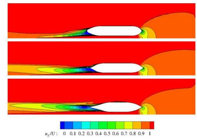
Figure 7: RANS predicted axial velocity uX/U contours around the tanker in the horizontal plane
( h/T=1.1,yR/B=0.758 )
[From top to bottom: z/LPP=0,−0.032,−0.06]

Figure 8: Pressure distribution on the hull surface
( h/T=1.1,yR/B=0.758 )
(Bottom view) upper: potential flow; lower: RANS
The predicted forces and moments by the RANS method are shown in the following figures, where only the zero level is given, as mentioned above. However no results from the potential flow method are presented here as it is indicated from the predicted sinkage and trim and the pressure distribution that viscous effects cannot be neglected. The results for the X′,Y′ forces and the K′,N′ moments at a specific ship-bank distance, yR/B=0.758, versus water depth ratio are shown in Figure 9a and 9b. Results at a specific water depth ratio h/T=1.35 versus ship-bank distance are shown in Figures 10a and 10b.
Comparing with the measurements, the tendencies of the forces and moments are captured well. As seen in Figure 9 a and 9 b , when the hull bottom approaches the seabed,
the X′ force and K′ moment become larger, while the Y′ force (a suction force towards the bank) behaves in a different way. It increases between h/T=1.5 and 1.35 , but drops rapidly between h/T=1.35 and 1.1. The N′ moment shows a monotonic increase for diminishing water depth as well, but in contrast with the measured data the predicted yaw moment changes from a bow in to a bow out moment between h/T=1.5 and 1.35 . However, the magnitudes of the yaw moment are very small. In Figure 10a and 10b, with varying ship-to-bank distance at h/T =1.35, the hull is attracted to the bank while the bow is pushed away.

Figure 9a, b: X′,Y′ force and K′,N′ moment versus h/T
While the tendencies of the predicted forces and moments correspond well with those of the measured data the absolute level is not well predicted in some cases. The most obvious difference between computations and measurements is seen in the Y′ force, for which there is a more or less constant shift to lower predicted values. This tendency is seen clearly in Figure 9a and 10a. To more quantitatively investigate the absolute accuracy a formal validation study was made. The validation procedure was based on the approach adopted in the 3rd Workshop on CFD Uncertainty Analysis [21]. Two parameters were introduced in this procedure, one is the validation comparison error denoted as E=S−D and the other is the validation uncertainty defined as UVal2=Unum 2+UD2. Here S and D represent the simulated solution and experimental data respectively. Unum is the numerical uncertainty, which is
approximated as the discretization uncertainty US in the grid convergence study (since the iterative uncertainty is neglected), and UD is the data uncertainty in the measurements. Here it is estimated as the standard deviation of measured variables in repeated captive shallow water model tests at FHR for the SIMMAN 2012 Workshop [22]. In this way, the precision error is accounted for, but not the bias error.
If ∣E∣≤UVal, the error is within the “noise level” and not much can be said about the modelling error; but if ∣E∣>>UVal, the sign and magnitude of E could be used as to improve the modelling. Considering the available discretization and data uncertainties, the condition h/T =1.1 at yR/B=0.758 was selected for the validation of the X′,Y′,K′,N′ prediction. The measured data (D) was used to normalize the estimated uncertainties and errors and the results are presented in Table 4.

Figure 10a, b: X′,Y′ force and K′,N′ moment versus yR/B
Table 4: Validation results of X′,Y′,K′,N′
| X′ | Y′ | K′ | N′ | |
|---|---|---|---|---|
| ∣UD%D∣ | 2.20 | 9.40 | 3.55 | 1.39 |
| ∣US%D∣ | 3.27 | 8.38 | 3.57 | 6.92 |
| ∣UVal%D∣ | 3.94 | 12.59 | 5.03 | 7.06 |
| ∣E%D∣ | 1.85 | 71.99 | 27.19 | 18.94 |
It is seen that three quantities Y′,K′ and N′, exhibit a larger comparison error than the validation uncertainty, which implies that there are significant modelling errors, in the computations and/or the measurements. The
neglected bias error in the measured uncertainty corresponds to a modelling error and has not been investigated in the present work. However systematic investigations of the modelling in the computations have been carried out and will be reported below.
There are several potential sources of modelling errors in the computations. Examples are: neglect of free surface, non-free sinkage and trim, turbulence modelling, boundary condition on the solid wall, and absence of propeller.
As mentioned before, the free surface effect was neglected in RANS computations. Its influence on hydrodynamic quantities is a concern. As shown in Figure 5 and 6, the computation of sinkage and trim indicates that without considering the free surface in RANS computations, the predicted sinkage and trim correspond very well with the measurements and the results of potential flow computations which take the free surface and free sinkage and trim into account. This shows that it is acceptable to neglect the free surface effect when predicting the sinkage and trim at the present low speed. However, the effect of the sinkage and trim on the other forces and moments, especially at the small water depths, is needed to be investigated. Thus, further computations with a given sinkage and trim from prior computations were carried on. The dotted lines in Figure 9 a and 9 b indicate the results with the initial sinkage and trim (σ&r). From the comparisons, it is interesting to see that the influence of sinkage and trim is generally very small. However, it cannot be neglected for the K′ and N′ moments at the very shallow water depth ( h/T=1.1 ), where the correction from sinkage and trim increases the ∣UVa%D∣ in N′ moment to 7.99% and reduces the ∣E%D∣ to 7.92%, while for other quantities the improvement is not large enough to reduce E to the UVal level, so there must be other significant modelling issues.
As for the turbulence modelling, the EASM model was used in the systematic computations. This turbulence model is capable of predicting more accurate wake profiles behind the hull in the deep water condition [23], but in the present case the hydrodynamic quantities were under-predicted with this model. Therefore another turbulence model, the Menter k−ω SST model [24] was applied to evaluate the influence of the turbulence modelling. The focus was placed on the computations with the variation of the bank distance at the same water depth h/T=1.35. Results are presented by dotted lines in Figure 10a and 10b for better comparison with the results of EASM model. As exhibited by the figures, there is a slight improvement in the prediction of sway force Y′ (the maximum decrease in ∣E%D∣ is around 8% ), but the improvement is very small compared to the difference between the computed and measured results. It should be pointed out that the massive separation mentioned above near the stern on the bank side of the hull may be influenced by the turbulence modelling. The prediction
of this separation is crucial for the prediction of the forces.
Moreover, a slip condition was satisfied at the walls (seabed, side bank) in the computations, but when the hull moves over/along the seabed/side bank, a boundary layer is developed on it due to the disturbance velocities from the hull. Therefore, the slip condition might be inadequate and a moving no-slip condition could be more suitable. Preliminary computations have indicated some effect, but this will be further investigated.
The last modelling error stated here is the absence of the non-rotating propeller. The evaluation of its influence on the flow field at the stern, and accordingly its contribution to hydrodynamic forces, will also be investigated in future work.
The investigation of bank effects by CFD methods is a challenging work due to the importance and complexity of the hydrodynamic problem itself and the difficulty in modelling the physical problem by numerical tools. The present work attempts to compute the bank effects by applying a viscous flow method to predict the sinkage and trim and the hydrodynamic forces for varying water depths and ship-to-bank distances. The results show that it is possible to predict sinkage and trim very accurately in bank-effect investigations. Tendencies of the viscous hydrodynamic forces and moments are also well predicted, but the absolute level of some quantities, notably the sway force, is less accurate. A formal validation analysis showed that there are modelling errors in the computations and/or the measured data. Due to time restrictions the latter could not be investigated, but three types of computational modelling errors were discussed, and shown to have some effect on the results. However, the improvement could not fully explain the differences between the computed and measured results. Further work to investigate the differences is underway.
The computing resources were provided by C3SE, Chalmers Centre for Computational Science and Engineering. All model tests were carried out in the Towing Tank for Manoeuvres in Shallow Water (cooperation Flanders Hydraulic Research - Ghent University). The authors thank Professor Marc Vantorre for his review of this article.
21.http://maretec.ist.utl.pt/html_files/CFD_workshops/W orkshop_2008.htm.
22. Delefortrie, G., Eloot, K., Mostaert, F., ‘SIMMAN 2012: Execution of model tests with KCS and KVLCC2. Version 2_0, WL Rapporten, 846_01’, Flanders Hydraulics Research, Antwerp, Belgium, 2011.
23. Zou, L., Larsson, L., ‘CFD Prediction of the Local Flow around the KVLCC2 Tanker in Fixed Condition’, Proceedings of A Workshop on Numerical Ship Hydrodynamics, Gothenburg, Sweden, 2010.
24. Menter, F.R., ‘Zonal Two Equation k-eo Turbulence Models for Aerodynamic Flows’, 24th Fluid Dynamics Conference, Orlando, AIAA paper 93-2906, 1993.
Lu Zou is a PhD student at the Department of Shipping and Marine Technology, Chalmers University of Technology, Sweden. Her PhD project is mainly focused on the CFD prediction of the hydrodynamic forces and moments on a manoeuvring ship in restricted water. Some of her research interest is in the V&V for CFD simulations.
Lars Larsson is a Professor of Hydrodynamics at Chalmers University of Technology. Formerly head of the Department of Naval Architecture and Director of the Rolls-Royce University Technology Centre for
Computational Hydrodynamics. Chairman and former Managing Director of the CFD software company FLOWTECH International AB. Author of more than 120 papers on CFD in hydrodynamics, and the author of two books.
Guillaume Delefortrie, PhD , is junior expert nautical research at Flanders Hydraulics Research, Belgium. His MSc project dealt with the modelling of bank effects. He is presently in charge for the experimental research in ship hydrodynamics at Flanders Hydraulics Research and the development of mathematical manoeuvring models in shallow and confined waters.
Evert Lataire, MSc, is assistant at the Maritime Technology Division of Ghent University, Belgium. He performs PhD research on bank effects and co-organised the 1st International Conference on Manoeuvring in Shallow and Confined Waters: Bank Effects in 2009.
2016
The present study investigates the hydrodynamic interaction between two vessels, an LNG tanker and a container ship, advancing in parallel in the close proximity of a bank using an unsteady Reynolds-averaged Navier-Stokes (URANS) simulation. The study focused on the simultaneous effect of ship-ship interactions and the presence of the bank in the vicinity. Computations were carried out for the following various scenarios: (1) single ship bank effect, (2) two-ship interaction and (3) simultaneous effect of the bank and the presence of a nearby ship. Through a comparative CFD analysis, this study reveals the behaviours of the hydrodynamic forces and moments acting on the vessels and the changes in the flow field when the bank effect and ship-ship interaction complement each other. Apart from the CFD simulation, model tests were carried out for validation purposes. The overall results of the numerical simulation showed fairly good agreement with the experiment, though there was a high validation comparison error in some cases, indicating challenges in CFD prediction. NOMENCLATURE α Bank slope (-) B Ship's breadth (m) C B Block coefficient (-) D Experimental data value (-) Fn Froude number [U/√(gL)] g Acceleration of gravity (ms-2) h Water depth (m) L pp Length between perpendiculars (m) N Yaw moment (Nm) N' Non-dimensional yaw moment (-) o Earth bound coordinate system (-)
2016
The authors were inspired by the benchmark model test data in MASHCON [1, 2] and carried out some numerical studies on ship-bank, ship-bottom and ship-ship interactions based on potential flow method in the last few years. In the confined waterways, many researchers question the applicability of the classical potential flow method. The main objective of the present paper is to present some validations of the 3D boundary element method (BEM) against the model test data to exam the feasibility of the potential method in predicting the hydrodynamic behaviour of the ships in confined water. The methodology used in the present paper is a 3D boundary element method based on Rankine type Green function. The numerical simulation is based on the in-house developed multi-body hydrodynamic interaction program MHydro. We calculate the wave elevations and forces (or moments) when the ship is manoeuvring in shallow and narrow channel, or when the two ships is travelling side by side or crossing each other. These calculations are compared with the benchmark test data, as well as the published CFD results. Generally, the agreement between the present calculations and model test and CFD results are satisfactory, which indicates that the potential flow method and developed program are still capable to predict the hydrodynamic interaction involved in ship-bank, ship-bottom and ship-ship problem.
Polish Maritime Research, 2019
On inland waterways the ship resistance and propulsive characteristics are strictly related to the depth of the waterway, thus it is important to have an understanding of the influence of water depth on ship hydrodynamic characteristics. Therefore, accurate predictions of hydrodynamic forces in restricted waterways are required and important. The aim of this paper is investigating the capability of the commercial unsteady Reynolds–Averaged Navier–Stokes (RANS) solver to predict the influence of water depth on ship resistance. The volume of fluid method (VOF) is applied to simulate the free surface flow around the ship. The hull resistance in shallow and deep water is compared. The obtained numerical results are validated against related experimental studies available in the literature.
international journal of engineering trends and technology, 2014
Practical application of Computational Fluid Dynamics (CFD) for predicting flow pattern around a ship hull and calculation of total resistance has been a topic of great interest for researchers in ship hydrodynamics. Today, several CFD tools have been developed to analyse and capture the free surface around a ship. The flow problem is rich in complexity and poses many challenges during simulation. Many mesh sizes were tried during modelling with Realizable − and shear stress Transport (SST) − turbulent models. The free surface wave pattern and the total resistance (shear and pressure resistances) were calculated. The effects of sinkage and trim were also studied using STAR-CCM+ software implementing a Reynolds averaged Nervier stokes (RANS) equation solver with free-surface capabilities. Predicted results were compared against empirical data showing good agreement. The method is found to be stable and is believed to predict the resistance for any ship with or without trim and sinkage.
International Journal of Materials, Mechanics and Manufacturing
This paper investigates various hydrodynamic characteristics of two conventional ships namely Wigley hull and Series 60 ship by commercial CFD software named Shipflow. Zonal approach is applied to incorporate 'potential flow solver' in the region outside the boundary layer and wake, 'boundary layer solver' in thin boundary layer region near the hull and 'Navier Stokes solver' in the wake region successively. Finally free-surface wave pattern, wave elevation, pressure coefficient on hull, boundary layer streamline and different resistance components at different speeds are computed and validated by comparing with experimental results.
Journal of Naval Architecture and Marine Engineering
Prediction of ship’s total resistance of a pusher-barge system has become enormous complexity involving nonlinear-hydrodynamic flows behaviour along their hull forms. Both of empirical and simplified numerical solutions may still lead into inaccurate results due to presence of nonlinear characteristics of the pressure and viscous resistances. The use of a more sophisticated method would obviously necessitate to solve the above problem. This paper presents a Computational Fluid Dynamics (CFD) approach to predict the total ship’s resistance of a pusher-barge system at various barge’s configurations. To achieve such objective, four different configurations of the barge models incorporated with various Froude numbers have been taken into account in the computational simulation. In general, the results revealed that the increase of Froude number (Fr = 0.182 to 0.312) was proportional to the magnitude of RT, RP and RV. Regardless of the various Froude number, the pusher-barge system with ...
Maneuverability and resistance prediction with suitable accuracy is essential for optimum ship design and propulsion power prediction. This paper aims at providing some of the resistance and maneuverability characteristics of a container ship model, MOERI KCS in calm water using a computational fluid dynamics solver named Ship Motion. The solver is based on the Reynolds average Navier-Stokes method (RaNS) and solves overset-structured grid using the Finite Volume Method (FVM). This paper comprises the numerical results of calm water test for the KCS model with available experimental results. The calm water test results include the total drag coefficient, average sinkage, and trim data. Visualization data for pressure distribution on the hull surface and free water surface have also been included. The paper concludes that the present solver has the capability to predict the resistance and maneuverability characteristics of the container ship with reasonable accuracy utilizing minimum computational resources.
2012
Viscous flow simulation of flow field around ships for manoeuvrability prediction has become a highly sought after issue now-a-days among the ship hydrodynamicists. As potential flow theory still lacks the versatility to consider the viscosity and flow separation effects in calculation, RANS simulation has gained its popularity in calculating detailed pressure and shear force distributions around drifting ships. The objective of this research work is to investigate the patter of flow around a manoeuvring tanker. An in-house code using unstructured grid based RANS solver has been developed to investigate the behavior of a ship in drifting motion. For unstructured grid the oscillations caused by the adoption of second order differencing scheme have been minimized through the implementation of a slope limiter algorithm in discretizing the diffusion term of the Navier-Stokes equation. A double hull model has been implemented in the manoeuvring simulation instead of considering the free surface flow. This approximation is justified when the ship speed is considered to be quite low (Fr<0.2) during drifting motion.
2015
Inland vessels typically spend most of their operation time in shallow and restricted waterways. For investigating the specific effects of such circumstances on ship hydrodynamics, ship model tests are carried out in the fully automated Towing Tank for Manoeuvres in Shallow Water (cooperation Flanders Hydraulics Research – Ghent University). In 2010, systematic captive model test series were carried out with a 1/25 scale model of a CEMT class Va inland vessel to provide the full bridge inland simulator Lara at Flanders Hydraulics Research with dedicated mathematical models for simulating the manoeuvring behaviour of this type of vessel. In particular, the effect of the presence of banks on ships navigating on a course parallel to these banks has been investigated. Based upon these model tests a mathematical model for the bank induced forces and moments has been developed. The influence on these bank effects is investigated and a mathematical model is implemented in the real time sim...