 Darshan Patel
580 California St., Suite 400
San Francisco, CA, 94104
Academia.edu no longer supports Internet Explorer.
To browse Academia.edu and the wider internet faster and more securely, please take a few seconds to upgrade your browser.
2023, International Journal of Innovative Research in Computer and Communication Engineering
https://doi.org/10.15680/IJIRCCE.2023.1105070…
10 pages
1 file
n developing country like India automotive industry growing rapidly. Growing automotive industry create pollution so government is taking initiative to curb the pollutions through Electric Vehicles. Electric vehicles (EVs) produce zero emissions at the tailpipe, which means that they do not release any pollutants or greenhouse gases into the air. This is in contrast to traditional gasoline-powered vehicles, which are a major source of air pollution and contribute to climate change. By reducing air pollution, EVs can help to improve air quality and protect the health of both humans and wildlife.However, one of the challenges with EV charging infrastructure in India is the lack of a comprehensive and coordinated strategy for its development. Currently, there are a number of different players involved in the development and operation of charging infrastructure, including government agencies, private companies, and electric utilities. This can lead to a fragmented and unevenly distributed charging network, which can be a significant hindrance for EV owners.Manufacturing of Electric vehicle supply equipment(EVSE) is complicated but its more complex to simulate therefore EVSE manufacturer want proper simulator that can measure the capacity, duty cycle, frequency and state change of it. This article includes all the parameter that EVSE manufacture want that can measure by simulator.
2018 IEEE International Telecommunications Energy Conference (INTELEC), 2018
Electric vehicles (EV) are rapidly invading the market, since they are clean, quiet and energy efficient. However, there are many factors that discourage EVs for current and potential customers. Among them, driving range is one of the most critical issues: running out of battery charge while driving results in serious inconvenience even comparable to vehicle breakdown, as an effect of long fuel recharging times and lack of charging facilities. As a result, the dimensioning of the energy subsystem of an EV is a crucial activity. The choice of the power components and of the adopted policies should thus be validated at design time through simulations, that estimate the vehicle driving range under reference driving profiles. It is thus necessary to build a simulation framework that takes into account an EV power consumption model, dependent on the characteristics of the vehicle and of the driving route, plus accurate models for all power components, including batteries and green power sources. The goal of this paper is to achieve early EV simulation, so that the designer can estimate at design time the driving range of the vehicle, validate the adopted components and policies and evaluate alternative configurations.
2023
to help with energy efficiency and Reduction of carbon. Electric vehicles (EVs) are eclipsing traditional IC engine vehicles in terms of market capitalization. The popularization of EVs leads to an increase in the number of charging points, which has a significant impact on the power grid. Various charging strategies and grid integration methods are being developed in order to mitigate the negative effects of EV charging and to maximize the benefits of EV grid integration. The article presents the projected greenhouse gas emissions for transportation system, as well as the existing EV status and a thorough review of EV charging, the types of chargers being used, types of batteries used, types of WPT used and the key future developments being made on a global and Indian scenario. Lastly, the challenges and recommendations for future EV charging development are summed up.
2010
Development of electric vehicle architectures requires complex analysis and innovative designs in order to produce a highly efficient mode of personal transportation acceptable to the target demographic. Using computer-aided modeling and simulation has been proven to decrease the development time of conventional vehicles while increasing overall success of the product design. Computer-aided automotive development also allows a fast response to the testing and inclusion of developing technologies in individual systems. Therefore, it follows to use this technique in the research and development of electric vehicles for consumer markets. This paper presents a system level model development and simulation for an electric vehicle using the Matlab-Simulink platform and its associated process. The current state of the art technologies for electric and plug-in hybrid electric vehicles are given to provide an introduction into the subject. Following, the project development is briefly described, detailing the specific goals for the project and the methods by which results were achieved. Next the paper discusses the analytical and simulation models for each key component as divided by the following systems: battery, charging, and traction. Model assembly and the development of a graphic user interface follows. Finally, the testing procedures for model validation, along with results, and future project works are provided.
2018
Research related to EV modeling in MATSim started in 2008/2009, with an electricity grids project (Waraich et al., 2013d); it's goal was to uncover potential bottlenecks and/or constraint violations in Zürich city's lower voltage grid due to future EV charging. A framework emerged from the research for EV modeling, called TESF (Transportation Energy Simulation Framework) (Waraich et al., 2014a). This resulted in various framework extensions and enabled simulation of various scenarios (Waraich et al., 2014a; Waraich, 2013; Abedin and Waraich, 2014; Schieffer, 2011; Galus and Andersson, 2011; Galus et al., 2012a; Bischoff, 2013; Bischoff and Maciejewski, 2014). This chapter provides advice on these research directions and serves as a starting point for modeling EVs in MATSim.
IRJET, 2022
In present scenario, air pollution has become a serious concern for the India. According to recent global report many cities in the India are most polluted cities. Major sector contributing to the air pollution are industrial sector and transport sector. Among this 51% of air pollution is caused by the industrial sector and 27% by electric the transport sector. Air pollution contributes to the premature deaths of 2 million Indians every year. In order to minimize the air pollution, vehicle (EV) can act as blessing in lowering the GHG (Green House Gases) emission. Electric as decreasing the pollution level and reduction in oil bills etc. Although there is considerable amount of threats in establishing the electric vehicles types of motor used for electric vehicles, batteries, and Architecture of Electrical vehicle in India
International Journal on Smart Sensing and Intelligent Systems
This paper reviews the battery technology, methods of charging techniques for charging the EV's battery, factors affecting the EV adaptation, India. Many significant methods recently used in electric vehicles are explained. In India, it has taken a major step in adapting the electric vehicle employing the Faster Adoption and Manufacturing of (Hybrid &) Electric Vehicles in India (FAME) scheme a government initiative. In the forthcoming years, electrification of transportation networks is a basic one while considering the consumption of petroleum derivatives just for the 50 years. Transportation is the most important source of logistics, and people contribute significant primary emissions to global warming, so avoid this situation by focusing on zero emissions. Transportation by electric vehicle is the lone achievable answer for these issues. This paper presents the effect of quick charging on Lithium-ion batteries in EVs. The Lithiumion battery is utilized to be essential energy...
international journal for research in applied science and engineering technology ijraset, 2020
Growing population increases the problem of growing pollution all over the globe. Population in India is about 135 crores and this number suggests the amount of pollution caused knowingly or unknowingly. Over the few decades it has been observed that the largest contributor to the pollution in India is the use of large numbers of automobiles or vehicles. Electric Vehicles prove to be one of the most efficient replacements to the fueled automobiles. These are just another automobiles or vehicles but run on electric power or electrical energy. This paper reviews the state of art of the electric vehicle concept, its advantages and benefits to the society and its power management strategies.
Lecture Notes in Mobility, 2015
The Project ASTERICS, an international EU-STREP Project with 10 partners from 7 countries, follows the target to increase the efficiency of fully electric vehicles (FEV) by means of improved virtual models and intelligent testing and verification methods. Better models in the early design-and development phases allow more realistic and improved concept studies and hence detailed optimization at component level as well as global optimization at system level. Through intelligent testing methods it will be possible to enhance the model quality on one hand and reduce the test time on the other hand. These testing methods shall also allow the assessment of durability and ageing effects for electrical components in the FEV-driveline. The combination of virtual simulation with realistic, for FEV relevant driving cycles leads to a very good possibility for optimization of predictable mileage. In this paper the results of the first phase of the ASTERICS project are presented. It describes the modelling approach and gives a good overview on virtual product development by means of model based system engineering (MBSE). Also described is the methodology to identify design goals based on real life data through assessment and definition of a representative driving cycle for FEV.
Proceedings of the 17th LACCEI International Multi-Conference for Engineering, Education, and Technology: “Industry, Innovation, and Infrastructure for Sustainable Cities and Communities”, 2019
SIDS (Small Island Developing States) are unique in their drive to reducing GHGs. Since these countries need to be self-sufficient in energy, there is a dilemma on the best way to reduce GHG while maintaining energy security. One way would be to drive the implementation of EVs for the transportation sector. However this can wreak havoc on the SIDS electrical network if not done properly. This paper reviews the possible effects of introducing EV charging on the grid. The authors have given Policy recommendations as to how EV penetration can be managed whilst maintaining the reliability and quality of the electricity grid. The authors also suggest a unique controller that can be used by the utility to limit charging time and window.
Energies
As fuel consumption in the transport sector has increased at a faster pace than in other sectors, the use of electromobility represents the main strategy adopted by the automotive industry. In this context, as the number of electrical vehicles (EVs) will increase, it will also be necessary to increase the number of charging stations. The present paper presents a complete solution for charging stations that can be located in the office or mall parking area. This solution includes a mode 3 AC charging stations of International Electrotechnical Commission (IEC) 61851-1 Standard, an EV simulator for testing the good functionality of the charging stations (i.e., communications, residual-current device (RCD) protection) and a software application used for controlling the charging process by the programmable logic controller (PLC).

e-ISSN: 2320-9801 | p-ISSN: 2320-9798

**Volume 11, Issue 5, May 2023**

**Impact Factor: 8.379**
1 Darshan Patel, 2 Tirth Patel, 3 Shail Rami, 4 Het Patel, 5 Prof. Nirav Mehta, 6 Dr. Anwarul Haque
1 UG Student, Power Electronics Dept., VGEC, Chandkheda, Ahmedabad, Gujarat, India
2 UG Student, IT Dept., SPEC, Vasad, Anand, Gujarat, India
3 UG Student, Power Electronics Dept., VGEC, Chandkheda, Ahmedabad, Gujarat, India
4 UG Student, Power Electronics Dept.,VGEC, Chandkheda, Ahmedabad, Gujarat, India
5 Assistant Professor, Power Electronics Dept., VGEC, Chandkheda,Ahmedabad, Gujarat, India
6 Assistant Professor, Power Electronics Dept., VGEC, Chandkheda,Ahmedabad, Gujarat, India
In developing country like India automotive industry growing rapidly. Growing automotive industry create pollution so government is taking initiative to curb the pollutions through Electric Vehicles. Electric vehicles (EVs) produce zero emissions at the tailpipe, which means that they do not release any pollutants or greenhouse gases into the air. This is in contrast to traditional gasoline-powered vehicles, which are a major source of air pollution and contribute to climate change. By reducing air pollution, EVs can help to improve air quality and protect the health of both humans and wildlife.However, one of the challenges with EV charging infrastructure in India is the lack of a comprehensive and coordinated strategy for its development. Currently, there are a number of different players involved in the development and operation of charging infrastructure, including government agencies, private companies, and electric utilities. This can lead to a fragmented and unevenly distributed charging network, which can be a significant hindrance for EV owners.Manufacturing of Electric vehicle supply equipment(EVSE) is complicated but its more complex to simulate therefore EVSE manufacturer want proper simulator that can measure the capacity, duty cycle, frequency and state change of it. This article includes all the parameter that EVSE manufacture want that can measure by simulator.
KEYWORDS: EVSE simulator, frequency measurement, EV Chargers, Voltage measurement, Duty Cycle
Electric Vehicle Supply Equipment (EVSE) is a vital component of the infrastructure required to support the growth of electric vehicles (EVs). It provides a safe and reliable means of recharging EVs by acting as an intermediary between the electric grid and the EV’s battery. There are different types of EVSEs available, such as Level 1, Level 2, and DC fast charging, each with their own charging rates and capabilities [9].However, one of the significant challenges in the development of it ensuring their compatibility and interoperability with EVs from different manufacturers. Therefore, it is essential to conduct thorough testing and validation of the charging systems to ensure their functionality, reliability, and safety [1]. It is cost-effective and efficient way to test and validate it before deployment.Most of the people think that EVSE work as phone charger. Electric Vehicle Supply Equipment (EVSE) and phone chargers are two very different types of chargers that serve different purposes. The main differences between EVSE and phone chargers are as follows:
| e-ISSN: 2320-9801, p-ISSN: 2320-9798| www.ijircce.com | |Impact Factor: 8.379 | || Volume 11, Issue 5, May 2023 ||
| DOI: 10.15680/IJIRCCE.2023.1105070 |
3. Charging Protocol: EVSEs use specific charging protocols, such as the SAE J1772 or CHAdeMO, to communicate with the EV’s onboard charger and safely transfer power to the battery. In contrast, phone chargers typically use universal charging protocols, such as USB or Lightning, to transfer power to the device.
4. Safety Features:It have several safety features, such as ground fault protection and overcurrent protection, to ensure the safe and reliable operation of the charging system. In contrast, phone chargers may not have the same level of safety features and may pose a risk of electric shock or fire if used improperly.
An EVSE simulator is a device designed to replicate the operation of a real charging station, allowing for various charging scenarios to be simulated. This simulation ensures that the EVSE is compatible and interoperable with different EVs.simulators are used to test the EVSE’s communication protocols, safety features, and charging capabilities. Moreover, they can also simulate different charging scenarios, such as low voltage or high voltage conditions, to test the response under different conditions [4]-[6].
In this research paper, we will discuss the significance of EVSEs in supporting the growth of EVs and the challenges faced in their development. We will explore the role of simulators in testing and validating the charging systems and how they ensure compatibility and interoperability of the EVSE with different EVs. Furthermore, we will delve into the different types of EVSE simulators, their features and applications in testing and validating EVSEs [7], [8].
EVSE is the infrastructure that provides electrical energy to charge electric vehicles (EVs). An EVSE typically consists of a charging station, a connector, and an interface between the station and the EV’s onboard charger. The charging station provides the electrical energy to the EV’s battery, and the interface communicates with the EV’s onboard charger to ensure safe and efficient charging.EVSEs come in various types and power levels, from Level 1 (120-volt AC charging) to Level 2 (240-volt AC charging) to Level 3 (DC fast charging). Level 1 charging is typically done using a standard household electrical outlet, while Level 2 and Level 3 charging require special charging stations that provide higher power outputs.EVSEs can be installed in a variety of locations, such as residential homes, commercial buildings, and public charging stations. They play a critical role in the adoption and growth of electric vehicles by providing a reliable and convenient way to recharge EVs [3], [9], [10].
The charging plug used by EVSE can vary depending on the type of connector and charging protocol used by the EV and the EVSE [2], [11]-[13]. Some common typescharging plugs include:
In addition to the physical plug, EVSEs also use a variety of communication protocols to communicate with the EV’s onboard charger and ensure safe and reliable charging. These protocols include CAN bus, Power Line Communication (PLC), and Ethernet.

Fig.1. AC & DC Connector Type

Fig. 2. Gun Pin Diagram
Table 1 Pin Description
| PIN | DESCRIPTION |
|---|---|
| L1 | AC line 1 |
| N | AC Neutral |
| PE | Protective Earth (Ground) |
| PP | Proximity Pilot /Plug Present, which provides a signal to the vehicle’s control system so it can prevent movement while connected to the electric vehicle supply equipment, and signals the latch release button to the vehicle. |
| CP | “Control Pilot” is a communication line used to signal charging level between the car and the EVSE, and can be manipulated by vehicle to initiate charging as well as other information. The signal is a 1 kHz square wave at ±12 volts generated by the EVSE to detect the presence of the vehicle, communicate the maximum allowable charging current, and control charging begin/end. |
An EVSE simulator is a tool used to simulate the behaviour of an electric vehicle charging station. An EVSE simulator is a valuable tool for anyone working with electric vehicle charging stations, whether it will be for testing, training, development, or research purposes. There are several reasons why it might be necessary, including:

Fig. 3. Flowchart of the System
3. Development:it can be used to develop new electric vehicle charging station technologies. By simulating the behaviour of a charging station, engineers can test and refine new technologies before deploying them in the real world.
4. Research:it can be used for research purposes, such as studying the impact of electric vehicles on the power grid or investigating the effectiveness of different charging station designs.
When the Gun of EVSE either in our hand or not connected to car then EVSE’s screen indicates normal blue light and voltage in gun’s pin across CP and PE pin it is 12 V . Secondly, when user connect gun with car and car connected properly then screen of it indicates yellow icon and voltage level id 9 V . Thirdly, when user reach payment interface then voltage level are 9 V PWM after complete imbursementEVSE simulator trip the relay and charging starts successfully and voltage level are 6V PWM. Simulator detect all state change and respond capture and give proper
| e-ISSN: 2320-9801, p-ISSN: 2320-9798| www.ijircce.com | |Impact Factor: 8.379 |
|| Volume 11, Issue 5, May 2023 ||
| DOI: 10.15680/IJIRCCE.2023.1105070 |
output like frequency conversation duty cycle measure and also identify the rating of EVSE. Accordingly every output simulator shows every response on its screen. Fig 3 illustrates the Flow chart of system.
The hardware elements of an EVSE simulator, such as a microprocessor, power supply, and interface circuits, make up its usual system design. The software components of an EVSE simulator typically include firmware that controls the hardware components and simulation software that models the behaviour of EVs and EVSEs. The system architecture seeks to ensure the dependability and safety of EVSEs and EVs by properly simulating real-world charging circumstances. We take analog and digital signal from EVSE’s CP pin. Fig. 4 shows the block diagram of the system.

Fig. 4. Block diagram
ATmega328 is a heart of EVSE simulator. For continuous analog and digital signal analysis Microcontroller unit (MCU) plays vital role in it. Moreover, LCD interfacing is also depending on MCU.It has a 32 KB flash memory, 2 KB SRAM, and 1 KB EEPROM. The ATmega328 has an 8-bit RISC architecture and operates at a clock frequency of up to 20 MHz It is widely used in various applications, including industrial automation, robotics, and consumer electronics. In this project it will continuously measure voltage through voltage divider on analog pin as well as frequency on digital pin. It is also capable to show different output based on voltage on LCD display. ATmega328 shown in Fig. 5.

Fig.5. ATmega328
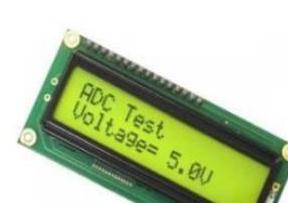
Fig. 6. 16∗2 LCD

Fig.7. LM2596
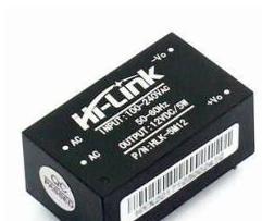
Fig.8. SMPS
B. 16∗2 LCD display: -
A 16×2 LCD is a liquid crystal display (LCD) module that can display up to 16 characters per line and up to 2 lines of text. For display State changes, Duty cycle and rating etc. we used this display in our project.A 16∗2 LCD is shown in Fig. 6.
The LM2596 module is a voltage regulator module based on the LM2596 integrated circuit (IC). The LM2596 is a step-down (buck) switching regulator IC that can convert higher voltage DC power into lower voltage DC power rather than showing IC and its peripheral, we can visualize whole module in Fig. 7.
Switched Mode Power Supply (SMPS), is a type of power supply that uses high-frequency switching to convert electrical power from one form to another. The main advantage of SMPS over traditional linear power supplies is their high efficiency, compact size, and low heat generation. In our project we use SMPS for converting the input power supply to the required output voltage and current levels. They use a switching regulator to efficiently convert the DC voltage from the power source to the desired voltage and components. In our case it will convert 220V AC Supply into 12 V DC supply. A SMPS which used in project is shown in Fig. 8.
Relay is an electromechanical switch which can only operate by signal which one fed by MCU. In EVSE simulator we use relay for automation purpose.Relays play a crucial role in the EVSE simulator by controlling the flow of power to the simulated EV. Relay will operate according to EVSE state change and relays also protect the EV and the EVSE from damage due to overvoltage, overcurrent, or short circuits. Its precise and reliable operation ensures the safety and accuracy of EVSE simulations. For driving relay separate driver circuit needed which is shown in Fig. 9 .

Fig.9. Relay Driver Circuit
The Arduino Integrated Development Environment (IDE) is an open-source software tool used for programming and developing Arduino boards. It provides a user-friendly interface for writing, compiling, and uploading code to Arduino boards. The IDE supports various programming languages, including C++, and offers a wide range of libraries and examples to facilitate development. The IDE is cross-platform and can run on Windows, Linux, and macOS. Its simplicity, versatility, and community support make it a popular choice for hobbyists and professionals alike in the development of embedded systems. Fig. 10 shows Arduino IDE window.
The prototype can be divided into four major functional parts.
A. Control circuit
| e-ISSN: 2320-9801, p-ISSN: 2320-9798| www.ijircce.com | |Impact Factor: 8.379 |
|| Volume 11, Issue 5, May 2023 ||
| DOI: 10.15680/IJIRCCE.2023.1105070 |
This part serves as the brain of the EVSE Simulator. ATmega328P accepts the signal coming from the sensing circuit and is responsible for the control and coordination of all the different components used in the project. Fig. 11 show the PCB layout of the control circuit as well as final PCB.
B. Sensing unit
For frequency and constant voltage measurement we have made sensor from various voltage divider circuit. signal pass through voltage divider and divider gives output to MCU.
C. Display/status indicator unit
State change of EVSE, frequency, duty cycle and EVSE rating and other relevant data displayed to the user on LCD (Liquid Crystal Display).
D. Power circuit
It includes a 3.3 V and 12 V power supply which is required to power the MCU and display. The circuit is simple andit includes a SMPS, capacitors used as filters and voltage regulators.
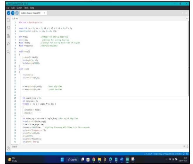
Fig. 10. Arduino IDE program

Fig. 11. PCB of simulator
The final result and analysis we obtain by testing the product was quite productive and with no errors after several testing and analysis. Fig 12 shows the test setup and the results. The various result analysis is shownthroughthe figures givenbelow:
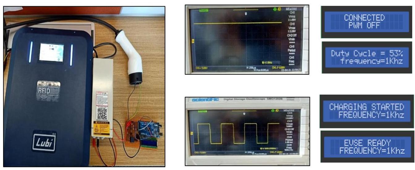
Fig. 12. Test Setup and results on simulator screen (Courtesy by: Lubi Industries LLP, Gujarat, India)
The development of an EVSE simulator is an important step towards the wider adoption of electric vehicles. This simulator can be used to test and evaluate different charging scenarios, which can help in the design and implementation of more efficient and reliable EVSE infrastructure. The research paper illustratesthe effectiveness of the proposed simulator. The simulator provides a realistic environment for testing various charging scenarios, and it can help in identifying potential issues before they occur in real-world scenarios. The prototype is still in its early stages and a lot of work still needs to be done. There are several limitations of EVSE simulator which is compatible with all AC Standards but not compatible with DC chargers. Secondly, due to the constant power supply, it may get damage due to overheating or power supply may get off. Thirdly, we can replace 10-bit MCU. Moreover, we can add new functionality like Ground Fault Detection Features and Over Current measurement features.


www.ijircce.com

International Journal for Research in Applied Science & Engineering Technology (IJRASET), 2022
Nowadays we are looking for economic development that is conducted without depletion of natural resources. Taking this into account the main motive of today's automotive industry is to reduce the use of contemporary automobiles and introduce renewable energy into the transportation sector. Vehicles running on natural gases are widely used in India in the public transport sector and taxis. The next revolution is expected in Electric Vehicles. Governments promote the use of EVs in private and public sector transportation by providing subsidies and other facilities. The scope of EVs in the Indian automobile market is increasing day by day. But along with that EV manufacturers and users are facing some challenges like battery charging time, temperature aspects, and higher manufacturing costs. This paper includes a review of the challenges and possible solutions. The role of engineers in the EV industry put forward so many opportunities to aspiring engineers. the role of different engineering streams is reviewed in this paper. Keywords: Electric Vehicles(EV), Battery Management System(BMS). I. INTRODUCTION Electric transportation offers ideal opportunities for the broader introduction of renewable to the transport sector. Along with that, these types of innovations and implementations help technical professionals like engineers to choose their dream roles and dream career. Before discussing the opportunities, we need to talk about the popularity of electric transportation methods like Battery Electric Vehicles (BEVs). The electric automobile market in India is growing over the last few decades and the authorities are expecting more than 30% of vehicles to be electric or hybrid by 2030. According to the Ministry of Skill Development and Entrepreneurship (MSDE), the electric automobile industry is going to create a huge number of jobs in the next 10 years in India. NITI Ayog and the Government of India are looking forward to the EV industry supporting the country's economic growth. To encourage this growth the central and state government have launched schemes and incentives and some regulations and standards are also in place. II. SCOPE OF ELCTRIC VEHICLES Sustainable development is an organizing principle for meeting human development goals while also sustaining the ability of natural systems to provide the natural resources and ecosystem services on which the economy and society depend [1]. The Electric Vehicle industry in India is growing so fast. India is the 4th largest vehicle market in the world. The large-scale adoption of Battery Electric vehicles and Hybrid Electric vehicles could bring significant changes to our society. This change will be visible in transportation technology. However, this will enable our nation's economy away from imported petroleum. When we look at the mobility challenges faced by the rapidly growing population in Indian cities, the air pollution caused by vehicular tail pipe emission is a primary concern. The second big problem, for which looks almost impossible to solve, is the traffic congestion that slow down the traffic and cause loss of productivity. The overall effect of Electric Vehicles is that it provides people with an alternate, costeffective solution for transportation. Along with this, we can save fossil fuels from running out prematurely and save our environment. The technology foundation for sustainable mobility is laid by electric vehicle (EV) technology that offers intrinsically high energy conversion efficiencies and zero vehicular tailpipe emission. The introduction of connected technologies in an EV makes it smart and creates unique value for customers. The moderate progress in the electrification of the automotive industry includes the hybrid vehicle, which acts as an alternative to conventional vehicles because of their performance and emission characteristics. Hybrid vehicles are designed with the combined advantages of IC engines and electric vehicle systems to overcome the shortfall of emissions, fossil fuel depletion, and range anxiety. Moreover, hybrid vehicles can be configured to obtain various objectives, such as better fuel efficiency, fewer emissions, reducing the wastage of energy, energy recovery while braking, size reduction in engines, etc. Clean energy and sustainable mobility are key drivers shaping our future. Disruptive technologies such as IoT, AI, ML, Advanced materials Additive manufacturing, Renewables and Energy storages are exponentially growing in their performance and their cost is falling very significantly [1]. Solar charging stations for electric vehicles have emerged as one of the best ways to reduce worlds dependence on fossil fuels for powering various modes of transport. This is due to the fact that electric vehicles are generally powered by electricity produced by fossil fuels, which is a massive cause of concern. As electric vehicles are getting more and more popular,
Modeling and Simulation for Electric Vehicle Applications, 2016
The objective of this chapter is to underline the importance of pre-production and prototyping simulation in the loop of electric vehicles, by considering as many vehicle characteristics as possible. Basic simulations were made, using IPG CarMaker, to simulate electric vehicles with different properties for batteries, transmission, electric motors, aerodynamics of the vehicle, and most importantly, driver properties. This chapter also explains all the necessary steps to create a model and run it in IPG CarMaker, including data exports, so that the results could be reproduced easily. This chapter underlines the importance of batteries and answers the questions: what is the correct number of batteries that a vehicle must equip in order to have a bigger range? Basically, one should carry more batteries that add weight but at what range in price.
2012
Vehicle electrification – where the usual vehicle drives are combined with or replaced by electrical drive concepts – makes particularly tough demands on the development process and development methods compared with the conventional development of vehicles. Because electric and hybrid electric drive concepts involve technologies from many domains and disciplines, there is a growing need to validate design and concept decisions in very early development phases. It is not only a question of validating the individual ECU functions required for electrification, such as energy management. It is more a matter of validating and testing their interaction with classic ECU functions. Thus, early validation requires solutions for simulating all the components involved, from the control functions to the networking of electronic control units (ECUs) to the mechanical and electrical vehicle components. This article presents a design and test environment for electric vehicles. The environment comp...
Energies
Recently, due to the growth of the electric vehicle (EV) market, the investigation of grid-to-vehicle and vehicle-to-grid strategies has become a priority in both the electric mobility and distribution grid research areas. However, there is still a lack of large-scale data sets to test and deploy energy management strategies. In this paper, a fully customizable EV population simulator is presented as an attempt to fill this gap. The proposed tool is designed as a web simulator as well as a Matlab/Simulink block, in order to facilitate its integration in different projects and applications. It provides individual and aggregated charge, discharge and plugin/out event data for a population of EVs, considering both home and public charging stations. The population is generated on the basis of statistical data (which can be fully customized) including commuting distances, vehicle models, traffic and social behavior of the owners. A peak-shaving case study is finally proposed to show the ...
International Journal of Engineering Applied Sciences and Technology, 2019
India is one of the largest automobile market in the world. Due to large numbers of automobiles are being used and growing sales of automobiles year-on-year. The fuel consumption increasing due to rising number of automobiles and energy demand of India; it is raising dependency on oil imports, expenses of foreign oil imports, emission issues etc. This all needs a sustainable mobility solution. Electric vehicles (EVs) are aligned with emobility and economic goals of the nation and strategic goal to reduce foreign crude oil dependency as well as emission/environmental issues. To mitigate the effects of global warming and the real solution can be provided by EVs. This paper highlights the present scenario and progress of EVs in India.
International Journal for Research in Applied Science & Engineering Technology (IJRASET), 2022
The global automobile industry is seeing a major shift towards e-mobility over the past decade. There is a rapid increase in concept cars being turned into production cars over the years. Following the suit, India also has big plans for the emerging Electric Vehicles and its technologies in the country. In this study it is aimed to highlight, counter and suggest some solutions to the challenges that lie ahead.
2021
An electric vehicle model is developed to characterize the behavior of the Smart e.d. (2013) while driving, charging and providing vehicle-to-grid services. The battery model is an electro-thermal model with a dual polarization equivalent circuit electrical model coupled with a lumped thermal model with active liquid cooling. The aging trend of the EV’s 50 Ah large format pouch cell with NMC chemistry is evaluated via accelerated aging tests in the laboratory. The EV model is completed with the measurement of the on-board charger efficiency and the charging control behavior via IEC 61851-1. Performance of the model is validated using laboratory pack tests, charging and driving field data. The RMSE of the cell voltage was between 18.49 mV and 67.17 mV per cell for the validation profiles. Cells stored at 100 % SOC and 40 °C reached end-of-life (80 % of initial capacity) after 431 days to 589 days. The end-of-life for a cell cycled with 80 % DOD around an SOC of 50 % is reached after ...
International Journal for Research in Applied Science & Engineering Technology (IJRASET), 2022
For the transportation sector, vehicle electrification is a game changer due to major energy and environmental implications driven by high vehicle efficiency i.e. EVs are approximately 3-4 times more efficient than comparable internal combustion engines vehicles (ICEV), zero tailpipe emissions, and reduced petroleum dependency as great fuel diversity and flexibility exist in electricity production. Far-reaching implications for vehicle grid integration extend to the electricity sector and to the broader energy system. The Indian Government is also planning to increase the electric vehicle in the automobile industries. In this paper the future and challenges of the electric vehicles in Indian market is discussed. The different factors like economic, social, technical and environmental which are affecting the electric vehicles market in India are discussed in this paper. The battery and infrastructure development are related to economic and technological factors. Based on the challenges, recommendations are made and it also helps to promote the market growth of electric vehicles.
EMERALD is a project funded by the European Commission under the FP7 program focusing on energy use optimization on the integration of the electric vehicles into the transport and energy infrastructure. Between the objectives of EMERALD, enhanced power demand prediction and power flow support management system uses the power flow demand simulation platform considered in this paper. The power flow demand simulation platform is a software tool that defines the estimation of electric vehicles power demand according to different conditions as, arrival and departure curves, the estimation of power production based on renewable energy sources and the electricity cost. The tool coordinates scheduling for charging of electric vehicles in order to minimize the recharging cost, considering the energy balance between the generation and demand power.
Central European Journal of Engineering, 2012
Electricity use for transportation has had limited applications because of battery storage range issues, although many recent successful demonstrations of electric vehicles have been achieved. Renewable biofuels such as biodiesel and bioethanol also contribute only a small percentage of the overall energy mix for mobility. Recent advances in hybrid technologies have significantly increased vehicle efficiencies. More importantly, hybridization now allows a significant reduction in battery capacity requirements compared to pure electric vehicles, allowing electricity to be used in the overall energy mix in the transportation sector. This paper presents an effort made to develop a Plug-in Hybrid Electric Vehicle (PHEV) platform that can act as a comprehensive alternative energy vehicle simulator. Its goal is to help in solving the pressing needs of the transportation sector, both in terms of contributing data to aid policy decisions for reducing fossil fuel use, and to support research...